1990 MITSUBISHI SPYDER air condition
[x] Cancel search: air conditionPage 1156 of 2103
AUTOMATIC TRANSAXLE
ENGINE (NON-TURBO)> Troubleshooting
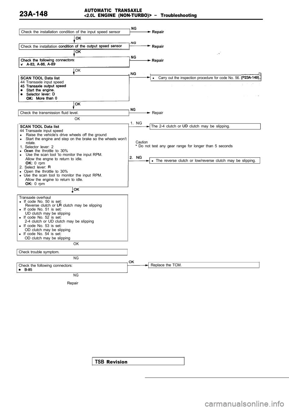
NGCheck the installation condition of the input speed sensor Repair
OK
NGCheck the installation Repair
NG Repair
l
OK
SCAN TOOL Data list lCarry out the inspection procedure for code No. 56.
44 Transaxle input speed
Check the transmission fluid level.
OK
SCAN TOOL Data list
44 Transaxle input speed l Raise the vehicle’s drive wheels off the ground
NG Repair
1. NG
The 2-4 clutch or clutch may be slipping.
l Start the engine and step on the brake so the wheel s won’t
rotate.1. Selector lever: 2
l the throttle to 30%
Caution Do not test any gear range for longer than 5 secon ds
l Use the scan tool ‘to monitor the input RPM.
Allow the engne to return to idle. OK: 0 rpm l
The reverse clutch or low/reverse clutch may be sli pping.
2. Select lever:
l Open the throttle to 30%
l Use the scan tool to monitor the input RPM.
Allow the enaine to return to idle.
OK: 0 rpm
Transaxle overhaul
l If code No. 50 is set:
Reverse clutch or
clutch may be slipping
l If code No. 51 is set:
UD clutch may be slipping
l If code No. 52 is set:
2-4 clutch or UD clutch may be slipping
l If code No. 53 is set:
OD clutch may be slipping
l If code No. 54 is set:
OD clutch may be slipping
OK
Check trouble symptom.
NG
Check the following connectors: Replace the TCM.
N G
TSBRevision
Repair
Page 1177 of 2103
AUTOMATIC TRANSAXLE
ENGINE (NON-TURBO)> On-vehicle .
FLUID LEAKAGE-TORQUE CONVERTER
HOUSING AREA CHECK
(1) Check for source of leakage.Since fluid leakage at or around the torque convert er
area may originate from an engine oil leak, the area should
be examined closely, Factory fill fluid is dyed red and,
therefore, can be distinguished from engine oil.
(2) Before removing the transaxle, perform the foll owing
checks:
When leakage is determined to originate from the tr ans-
axle, check fluid level before removal of the transaxle
and torque converter.
High oil level can result in oil leakage out the vent in
the manual shaft. If the fluid level is high, adjust to
proper level.
After fluid is at the proper level, check for leakage. If
a leak
perform the following operation on the
to determine if it is the torque converter or tran saxle
that is, leaking.
TORQUE CONVERTER LEAKAGE
Possible sources of torque converter leakage are:
(2) Torque converter weld leaks at the out side (pe ripheral)
weld. Torque converter hub weld.
(3) Hub
inside and not visible. Do not attempt to
repair.
Replace torque converter.
If the torque converter must be replaced, refer to Torque
Converter Clutch Break-in Procedure in this section . This
procedure’ will reset the transaxle control module break-in
status. Failure to perform this procedure may cause transaxle
shutter.
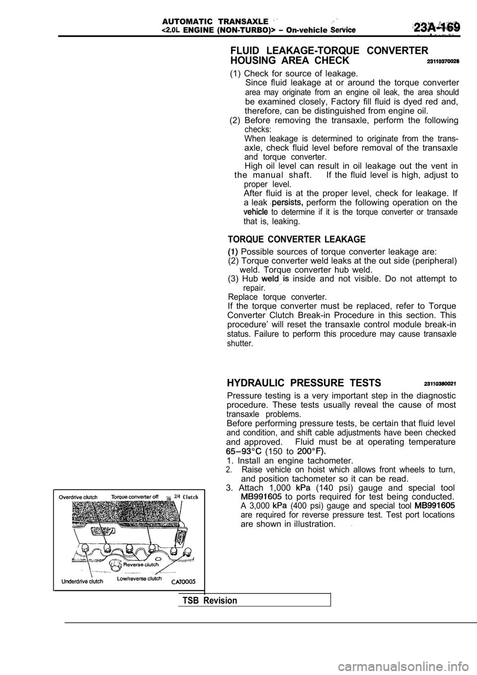
Clutch
HYDRAULIC PRESSURE TESTS
Pressure testing is a very important step in the diagnostic
procedure. These tests usually reveal the cause of most
transaxle problems.
Before performing pressure tests, be certain that fluid level
and condition, and shift cable adjustments have bee n checked
and approved.Fluid must be at operating temperature
(150 to
1. Install an engine tachometer.
2.Raise vehicle on hoist which allows front wheels to
turn,
and position tachometer so it can be read.
3. Attach 1,000
(140 psi) gauge and special tool
to ports required for test being conducted.
A 3,000 (400 psi) gauge and special tool
are required for reverse pressure test. Test port l ocations
are shown in illustration.
TSB Revision
Page 1647 of 2103
BASIC BRAKE SYSTEM
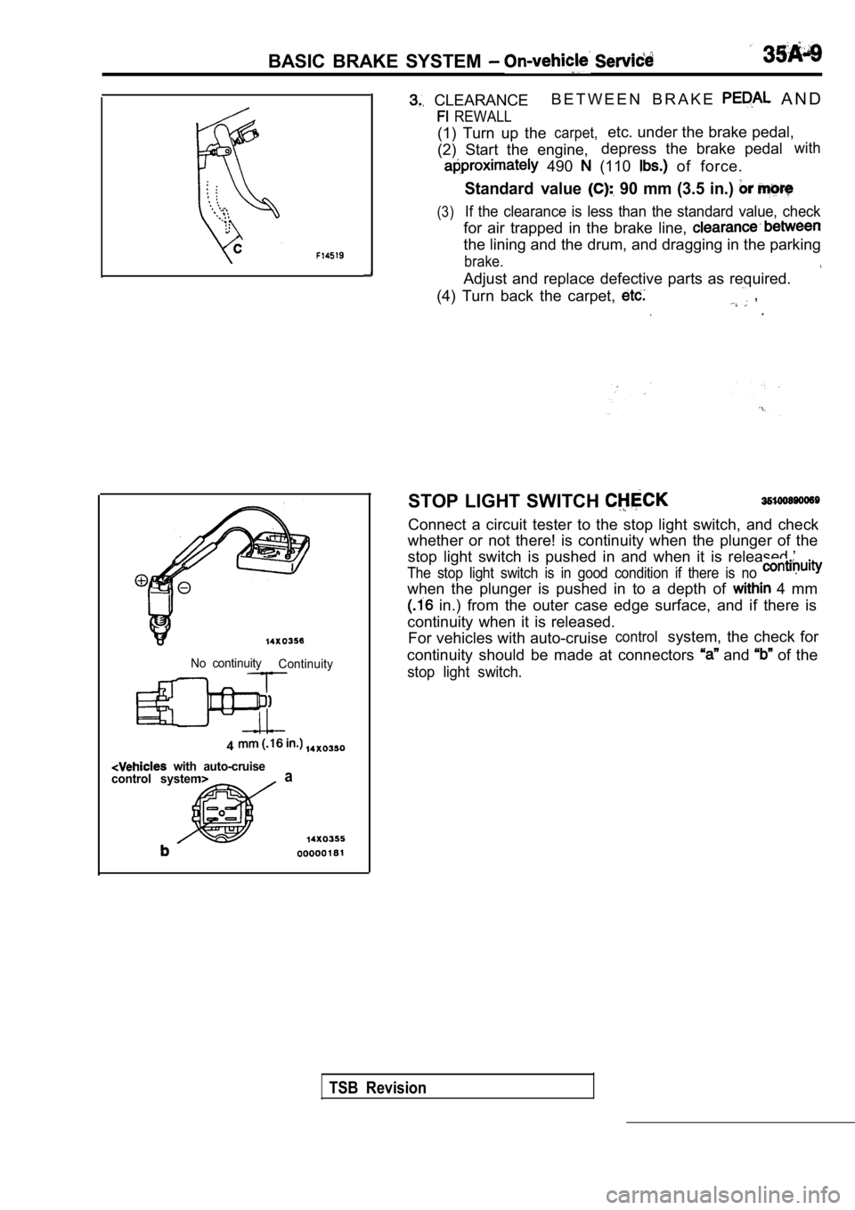
CLEARANCEB E T W E E N B R A K E A N D
REWALL
(1) Turn up thecarpet,etc. under the brake pedal,
(2) Start the engine, depress the brake pedal
with
490 (110 of force.
Standard value 90 mm (3.5 in.)
(3)If the clearance is less than the standard value, c
heck
for air trapped in the brake line,
the lining and the drum, and dragging in the parkin g
brake.
Adjust and replace defective parts as required.
(4) Turn back the carpet,
, .
No continuity Continuity
4
with auto-cruise
control systema
STOP LIGHT SWITCH
Connect a circuit tester to the stop light switch, and check
whether or not there! is continuity when the plunge r of the
stop light switch is pushed in and when it is relea sed.’
The stop light switch is in good condition if there is no
when the plunger is pushed in to a depth of 4 mm
in.) from the outer case edge surface, and if ther e is
continuity when it is released. For vehicles with auto-cruise
controlsystem, the check for
continuity should be made at connectors
and of the
stop light switch.
TSB Revision
Page 1651 of 2103
BASIC BRAKE SYSTEM
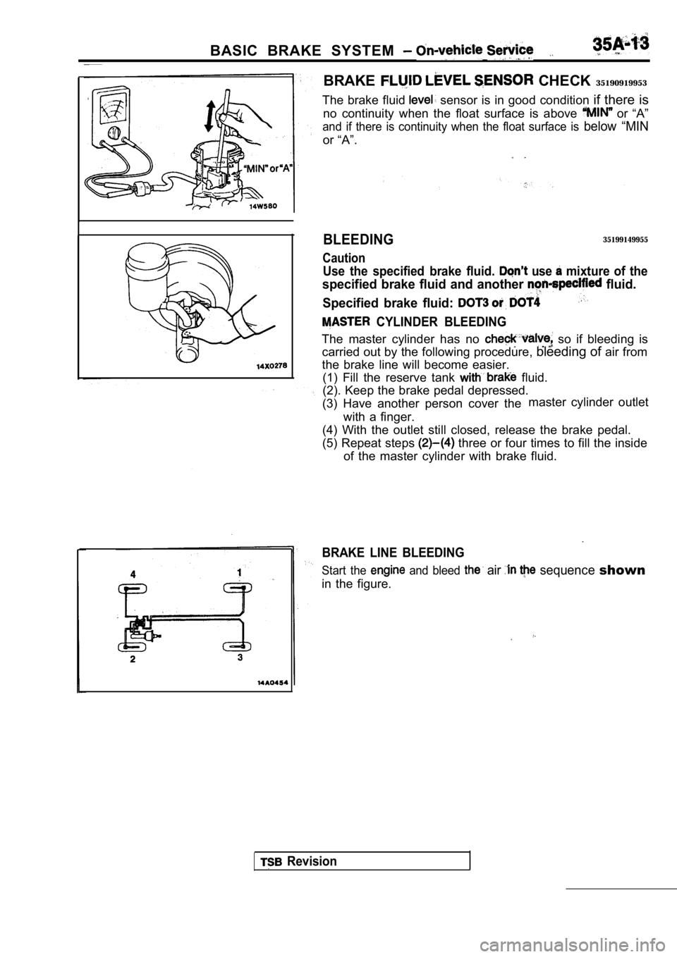
BRAKE CHECK 35190919953
The brake fluid
sensor is in good condition if there is
no continuity when the float surface is above
or “A”
and if there is continuity when the float surface i s below “MIN
or “A”.
BLEEDING
Caution
35199149955
Use the specified brake fluid. use mixture of the
specified brake fluid and another fluid.
Specified brake fluid:
CYLINDER BLEEDING
The master cylinder has no so if bleeding is
carried out by the following procedure, bleeding of air from
the brake line will become easier. (1) Fill the reserve tank
fluid.
(2). Keep the brake pedal depressed.
(3) Have another person cover the master cylinder outlet
with a finger.
(4) With the outlet still closed, release the brake pedal.
(5) Repeat steps
three or four times to fill the inside
of the master cylinder with brake fluid.
BRAKE LINE BLEEDING
Start the and bleed air sequence shown
in the figure.
Revision
Page 1663 of 2103
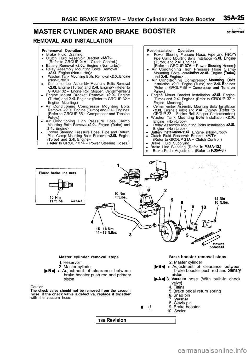
BASIC BRAKE SYSTEM Master Cylinder and Brake Booster
MASTER CYLINDER AND BRAKEBOOSTER
REMOVAL AND INSTALLATION
Pre-removal Operationl
Brake Fluid Draining
l Clutch Fluid Reservoir Bracket
(Refer to GROUP Clutch Control.)
l Battery Removal Engine (Non-turbo)>
l Relay Assembly Mounting Bolts Removal
Engine (Non-turbo)>
lWasher Tank Bolts Removal (Non-turbo)>lCentermember Assemblv Bolts Removal Engine (Turbo) arid Engine> (Refer toGROUP 32 Engine Roll Stopper, Centermember.)l Engine Mount Bracket Removal Engine
(Turbo) and Engine> (Refer to GROUP 32 Engine Mounting.)l Air Conditioning Compressor Mounting Bolts
Removal Engine (Turbo) and Engine>
(Refer to GROUP 55 Compressor and TensionPulley.)l Air Conditioning High Pressure Hose ClampMounting Bolts Engine (Turbo) and Engine>
l Power Steering Pressure Hose, Pipe and Return
Pipe Clamp Mounting Bolts Removal Engine and
I GROUP Power Steering Hoses.)
Flared brake line nuts
15 Nm11
Post-installation OperationlPower Steering Pressure Hose, Pipe and Pipe Clamp Mounting Bolts Installation Engine(Turbo) and Engine>
(Refer to GROUP Power Hoses.]
l Air Conditioning High Pressure Hose Clamp
Mounting Bolts
Engine and Engine>
l A i r C o n d i t i o n i n g C o m p r e s s o r
Installation Engine (Turbo) and ngines
(Refer to GROUP 55 Compressor and TensionPulley.)l Engine Mount Bracket Installation Engine(Turbo) and Engine> (Refer to GROUP 32 Engine Mounting.)lCentermember Assembly Mounting Bolts Installation Engine (Turbo) and Engine> (Refer toGROUP 32 Engine Roll Stopper Centermember.)l Washer Tank Mounting Installation Engine (Non-turbo)>l
Relay Assembly Mounting Bolts Installation Engine (Non-turbo)>l Battery Engine (Non-turbo)>
l Clutch Fluid Reservoir Bracket
(Refer to GROUP Clutch Control.)
l Brake Fluid Supplying
l Brake Line Bleeding (Refer to
l
Brake Pedal Adjustment (Refer to
I
10 Nm714 Nin10
Master cylinder removal steps
2. Master cylinder1.
Reservoir
l Adjustment of clearance between
brake booster push rod and primary
piston
CautionThe check valve should not be removed from the vacu umhose. If the check valve isdefective, replace it together
with the vacuum hose. Brake
booster removal steps
l Adjustment of clearance between
2. Master cylinder
brake booster push rod and
3. hose (With built-in check
4. Fittina 5.
pedal return spring
6. Snap pin
7.
8. pin
9. Brake booster
10. Sealerl b
TSBRevision
Page 1686 of 2103
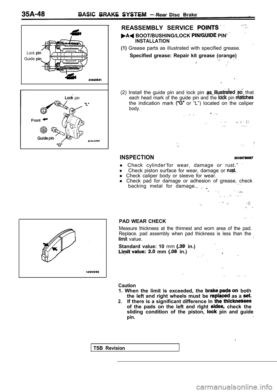
BASICBRAKESYSTEM Rear Disc Brake
Lock
Guide
pin
REASSEMBLY SERVICE
BOOT/BUSHING/LOCK PIN’
INSTALLATION
Grease parts as illustrated with specified grease.
Specified grease: Repair kit grease (orange)
..
(2) Install the guide pin and lock pin
that
each head mark of the guide pin and the pin
the indication mark or “L”) located on the caliper
body.
. .
INSPECTION
l Check cylinder’for wear, damage or rust.”
lCheck piston surface for wear, damage or
l Check caliper body or sleeve for wear.
l Check pad for damage or adhesion of grease, check
backing metal for damage.,
. .
, .
PAD WEAR CHECK
Measure thickness at the thinnest and worn area of the pad.
Replace. pad assembly when pad thickness is less th an the
value.
Standard value: 10 mm in.)
mm in.),
Caution
1. When the limit is exceeded, the both
the left and right wheels must be
as a
2.If there is a significant difference In
of the pads on the left and rlght check the
sliding condition of the piston,
pin and guide
pin.
,
TSB Revision
Page 1698 of 2103
![MITSUBISHI SPYDER 1990 Service Repair Manual ABS Troubleshooting
Code No. 16 Power supply system
[Comment]lMalfunction of wiring harness or connector,
This diagnostic trouble code is output when the ABS -ECU power voltage is outside
l MITSUBISHI SPYDER 1990 Service Repair Manual ABS Troubleshooting
Code No. 16 Power supply system
[Comment]lMalfunction of wiring harness or connector,
This diagnostic trouble code is output when the ABS -ECU power voltage is outside
l](/manual-img/19/57345/w960_57345-1697.png)
ABS Troubleshooting
Code No. 16 Power supply system
[Comment]lMalfunction of wiring harness or connector,
This diagnostic trouble code is output when the ABS -ECU power voltage is outside
l Malfunction of battery or generator’
the standard value. Furthermore, if the voltage ret urns to normal, this diagnostic
l Malfunction of ABS-ECU
trouble code will not be output.
Caution
If the battery voltage drops during check, this cod e will be output as a current
and correct
diagnostic of the problem cannot be made.
Before carrying out the following check, check the battery condition;
Measure at the ABS-ECU connector
l
OK
5 4 9 , and
NG Repair. .
Check the or
. N G Check the following connector:
OK
Check trouble symptoms Replace ABS-ECU.
Code No. Wheel speed sensor gap
or short circuit
[Comment]l Improper installation of wheel speed sensor
These diagnostic trouble codes are output when the detection speed of the wheellMalfunction of wheel speed sensor (intermittent ope nspeed sensors is below the standard value.
circuit or short circuit)lMalfunction of ABS rotor (chipped tooth or rotor notinstalled)l Noise interference in wheel speed sensor
l Malfunction of ABS-ECU ,
TSB Revision
NOTE
1. Momentary interruptions within approximately 100 ms are not detected.
2. To inspect the twisted pair wires in the wheel s peed sensor, check if there is
cables, and flex the cables to check for any open c ircuits.
NG Repair
(Refer to
NGWheel speed sensor checkReplace the wheel speed sensor.check(Refer to(Refer to
Wheelspeedsensorbody-side harness
Page 1708 of 2103
![MITSUBISHI SPYDER 1990 Service Repair Manual ABS Troubfeshooting , .
INSPECTION PROCEDURE 7
Break operation is abnormal
[Comment]This varies depending on the driving conditions and the road surface conditions, soproblem diagnosis is d MITSUBISHI SPYDER 1990 Service Repair Manual ABS Troubfeshooting , .
INSPECTION PROCEDURE 7
Break operation is abnormal
[Comment]This varies depending on the driving conditions and the road surface conditions, soproblem diagnosis is d](/manual-img/19/57345/w960_57345-1707.png)
ABS Troubfeshooting , .
INSPECTION PROCEDURE 7
Break operation is abnormal
[Comment]This varies depending on the driving conditions and the road surface conditions, soproblem diagnosis is difficult. However, if a normal diagnostic trouble code is displayed,carry out the following
l Malfunction of wheel speed l Malfunction of ABS rotor
l Malfunction of wheel bearing
of hydraulic Malfunction of ABS-ECU
NG Repair
(Refer to
Wheel speed sensor output voltage check [ R e p l a c e t h e w h e e l
Hydraulic unit check (Refer to 1NGABS rotor check (Refer to Replace the rotor.
O K NGWheel bearing end play check Refer to GROUP 26 On-vehicle Repair
Service.Refer to GROUP 27 On-vehicleIService.I
Check trouble symptom.
ABS-ECU connector l Disconnect the connector and
measure at the harness side.
l Resistance vaiue between termi-
nals
14-15, and
O KThe sensor harness and connector
should be moved while these checks
are carded out.
OK
Repair
TSB Revision
Repair
.
NG Repair
OK
Check trouble symptom.N G Replace ABS-ECU.