1990 MITSUBISHI SPYDER air condition
[x] Cancel search: air conditionPage 826 of 2103
E N G I N E A N D E M I S S I O N C O N T R O L ( T u r b o )
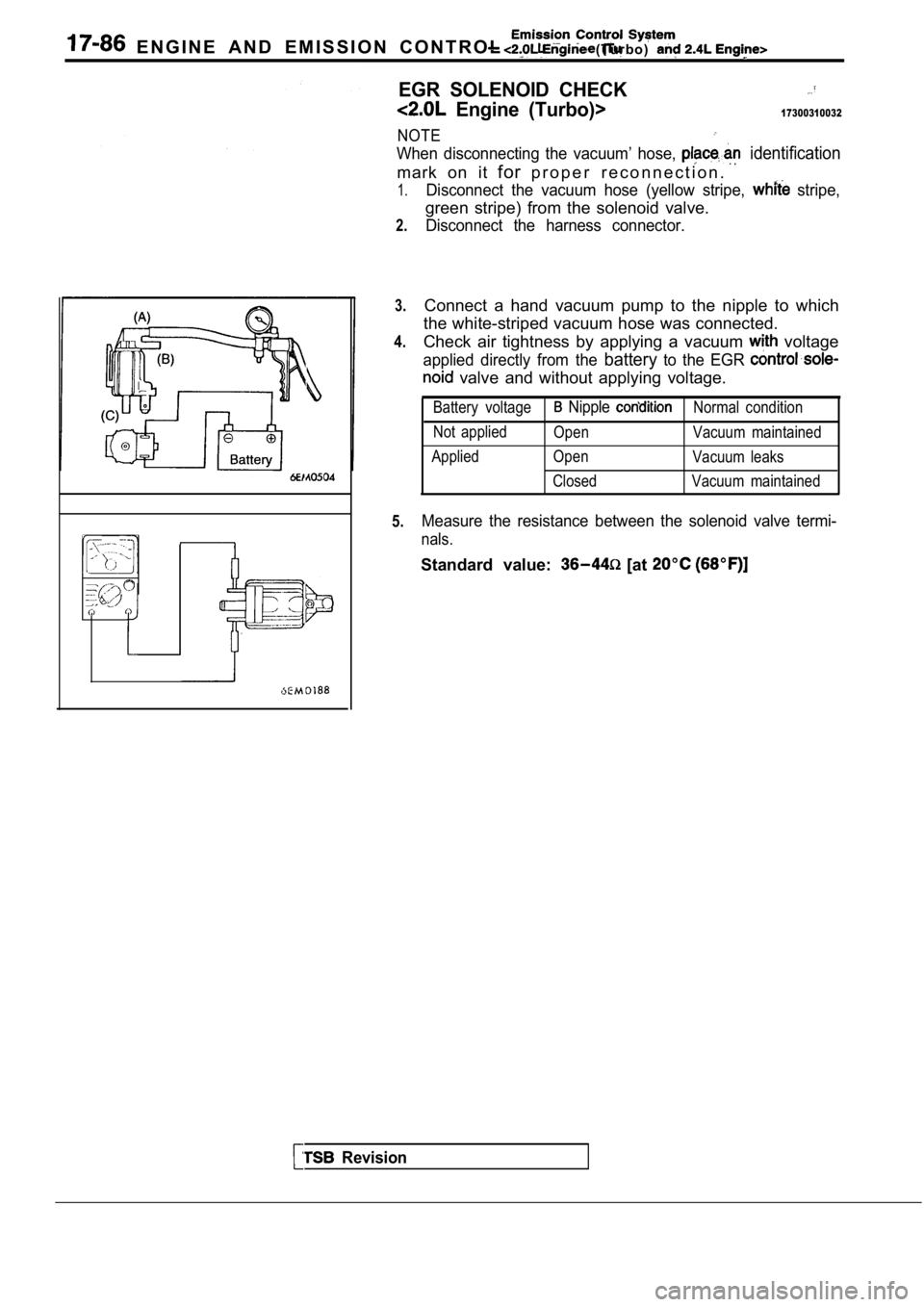
EGR SOLENOID CHECK
Engine (Turbo)>17300310032
NOTE
When disconnecting the vacuum’ hose, identification
mark on it forp r o p e r r e c o n n e c t i o n .
1.
2.
3.
4.
5.
Disconnect the vacuum hose (yellow stripe, stripe,
green stripe) from the solenoid valve.
Disconnect the harness connector.
Connect a hand vacuum pump to the nipple to which
the white-striped vacuum hose was connected.
Check air tightness by applying a vacuum
voltage
applied directly from the batteryto the EGR
valve and without applying voltage.
Battery voltage Nipple Normal condition
Not applied Open Vacuum maintained
Applied Open Vacuum leaks
Closed Vacuum maintained
Measure the resistance between the solenoid valve t ermi-
nals.
Standard value: [at
Revision
Page 827 of 2103

AND EMISSION CONTROL
Emission Engine
27
SOLENOID CHECK
NOTE,
When disconnecting the vacuum
mark on it for proper re-connection.
Disconnect the vacuum hose (yellow stripe; stripe)1.
2.
3.
4.
5.
from the solenoid valve;
Disconnect the harness connector.
Connect a hand vacuum to
Check air tightness by applying vacuum
directly from the battery to the solenoid
without applying voltage
Battery voltage
Applied Not appliedNormal condition
Vacuum maintained.
Vacuum
the between the terminals the sole-
noid valve.
Standard value: [at
.
,
TSB Revision
Page 986 of 2103
Output Disassembly/
MANUAL TRANSAXLE
Stop ring speedgear
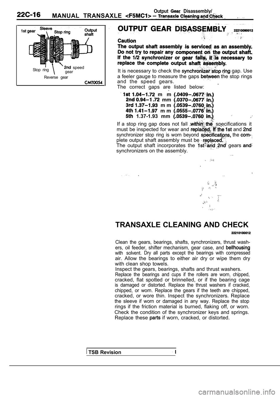
Reverse gearIt is necessary to check the gap. Use
a feeler gauge to measure the gaps
the stop rings
and the speed gears.
The correct gaps are listed below:
.
m m
mm
m m
m m
1.37-1.93 mm .If a stop ring gap does not fall specifications it
must be inspected for wear and
and
synchronizer stop ring is worn beyond the
plete output shaft assembly must be
The output shaft incorporates the gears
synchronizers on the assembly.
.
.. .
TRANSAXLE CLEANING AND CHECK
Clean the gears, bearings, shafts, synchronizers, t hrust wash-
ers, oil feeder, shifter mechanism, gear case, and
with solvent. Dry all parts except the bearings with compressed
air. Allow the bearings to either air dry or wipe t
hem dry
with clean shop towels. Inspect the gears, bearings, shafts and thrust wash ers.
Replace the bearings and cups if the rollers are wo rn, chipped,
cracked, flat spotted or brinnelled, or if the bearing cage
is damaged or distorted. Replace the thrust washers if cracked,
chipped, or worn. Replace the gears if the teeth are chipped,
cracked, or wore thin. Inspect the synchronizers. R eplace
the sleeve if worn or damaged in any way. Replace t he stop
rings if the friction material is burned, flaking off, or worn.
Check the condition of the synchronizer keys and sp rings.
Replace these
if worn, cracked, or distorted.
TSB Revision I
Page 1044 of 2103
![MITSUBISHI SPYDER 1990 Service Repair Manual AUTOMATIC TRANSAXLE
ENGINE (TURBO) AND ENGINE> ,
INSPECTION PROCEDURE 5 .
lDoes not move (forward or reverse)
[Comment]
P r o b a b l e c a u s e ‘
When the engine is idling, the ve MITSUBISHI SPYDER 1990 Service Repair Manual AUTOMATIC TRANSAXLE
ENGINE (TURBO) AND ENGINE> ,
INSPECTION PROCEDURE 5 .
lDoes not move (forward or reverse)
[Comment]
P r o b a b l e c a u s e ‘
When the engine is idling, the ve](/manual-img/19/57345/w960_57345-1043.png)
AUTOMATIC TRANSAXLE
ENGINE (TURBO) AND ENGINE> ,
INSPECTION PROCEDURE 5 .
lDoes not move (forward or reverse)
[Comment]
P r o b a b l e c a u s e ‘
When the engine is idling, the vehicle does not mov e forward or in reverse even if the selectorl
Abnormal reducing pressure
l
lever is shifted from
to 2, or range. In such cases, the cause is probably abnorm alMalfunction of power train
l
reducing pressure, or a defective oil pump or power train.Malfunction of oil pump
l ‘ o f v a l v e b o d y
Refer to Automatic Transaxle Overhaul
O K
Hydraulic pressure test (Refer to .
l Measure the reducing pressure in range while the
engine is idling.
Standard value:
psi)
NG
Reducing pressure OK
Power train check lDisassemble the transaxle, check the condition of t he
and repair or replace if necessary.
Check to be sure that there are no abnormalities su ch
lIf it is considered that the damage or chipping can
not
be repaired, replace the valve body assembly.If there is an abnormality, replace the oil pump as sembly.
INSPECTION PROCEDURE 6
l Engine stalling during shifting
cause
[Comment] Malfunction of engine systemWhen the engine is idling, the engine stalls when t he selector lever is shifted from to l
2, or range. In such cases, the cause is probably a defe ctive engine system or damper lMalfunction of torque solenoid
clutch control solenoid valve. Malfunction of body l
Malfunction of torque converter
Refer to Automatic Transaxle Overhaul
Enaine check .
l the control system, ignition system, fuel system a nd main engine system, and confirm that everything is l If there is an abnormality, repair or replace the e ngine system.
After completion
Solenoid valve connector check
l Check to be sure that there is no water in the conn ector.
l Check to be sure that none of the terminals are sho
rted to each other.
After completion
Torque converter clutch solenoid check l Check to be sure that the valve is not sticking due to foreign materials packed inside solenoid.
l If there is an abnormality, replace the solenoid as sembly.
After completion
Transaxle cooling system check l Check for plugged cooler lines.
l Check for plugged oil cooler.
After completion
Valve body disassembly, cleaning and reassembly
l
l Pay particular attention to loosening of bolts, and
to damage, chipping or slippage of O-rings, valve intermediate plate and body.
If it is considered that the damage or chipping can not be repaired, replace the valve body assembly.
After completion
Torque converter check l Check to be sure that there is no sticking due to s eparation from the damper clutch.
l If there is an abnormality, replace the torque conv erter assembly.
Revision
Page 1070 of 2103
AUTOMATIC TRANSAXLE
ENGINE (TURBO) AND ENGINE> On-vehicle Service
Revision
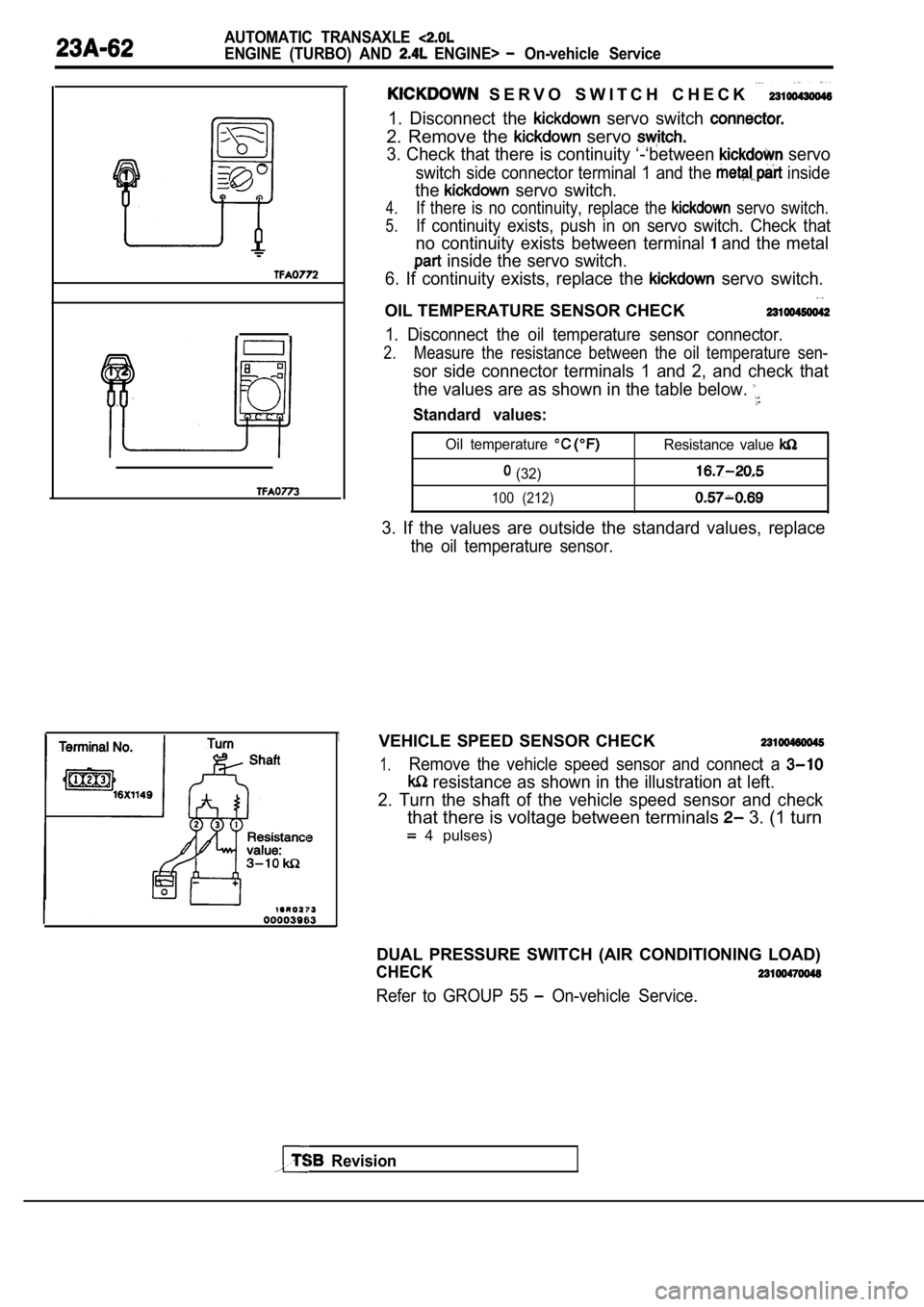
S E R V O S W I T C H C H E C K
1. Disconnect the servo switch
2. Remove the servo
3. Check that there is continuity ‘-‘between servo
switch side connector terminal 1 and the inside
the servo switch.
4.If there is no continuity, replace the servo switch.
5.If continuity exists, push in on servo switch. Check that
no continuity exists between terminal and the metal
inside the servo switch.
6. If continuity exists, replace the
servo switch.
OIL TEMPERATURE SENSOR CHECK
1. Disconnect the oil temperature sensor connector.
2.Measure the resistance between the oil temperature sen-
sor side connector terminals 1 and 2, and check that
the values are as shown in the table below.
Standard values:
Oil temperature Resistance value
(32)
100 (212)
3. If the values are outside the standard values, r eplace
the oil temperature sensor.
VEHICLE SPEED SENSOR CHECK
1.Remove the vehicle speed sensor and connect a
resistance as shown in the illustration at left.
2. Turn the shaft of the vehicle speed sensor and c heck
that there is voltage between terminals 3. (1 turn
4 pulses)
DUAL PRESSURE SWITCH (AIR CONDITIONING LOAD)
CHECK
Refer to GROUP 55 On-vehicle Service.
Page 1080 of 2103
AUTOMATIC: TRANSAXLE
ENGINE AND On-vehicle Service
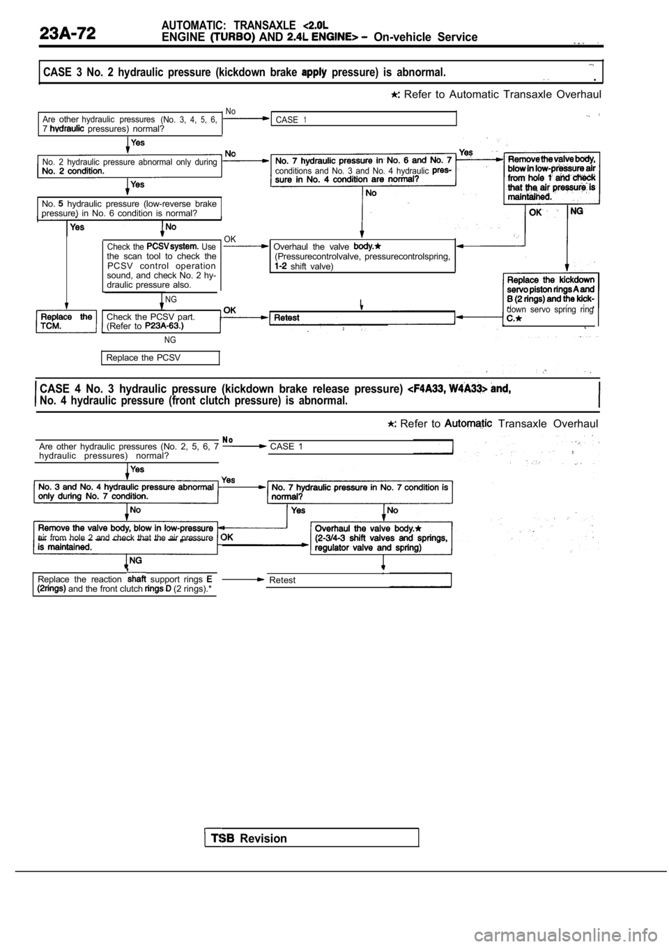
CASE 3 No. 2 hydraulic pressure (kickdown brake pressure) is abnormal. .
Refer to Automatic Transaxle Overhaul
NoAreotherhydraulic pressures(No.3, 4,5,6,CASE17 pressures) normal?
No. 2 hydraulic pressure abnormal only during
conditions and No. 3 and No. 4 hydraulic
No. hydraulic pressure (low-reverse brake
pressure) in No. 6 condition is normal?
Check the Usethe scan tool to check the
PCSV control operation
sound, and check No. 2 hy-
draulic pressure also.
NG
OK Overhaul the valve (Pressurecontrolvalve, pressurecontrolspring, shift valve)
I
Check the PCSV part.
(Refer to
,down servo spring ring
NG
Replace the PCSV
CASE 4 No. 3 hydraulic pressure (kickdown brake rel ease pressure)
No. 4 hydraulic pressure (front clutch pressure) is abnormal.
Refer to Transaxle Overhaul
N oAre other hydraulic pressures (No. 2, 5, 6, 7 CASE 1
hydraulic pressures) normal?
air from hole 2 and check that the air pressure
and the front clutch (2 rings).*
Replace the reaction support rings , Retest
Revision
Page 1142 of 2103
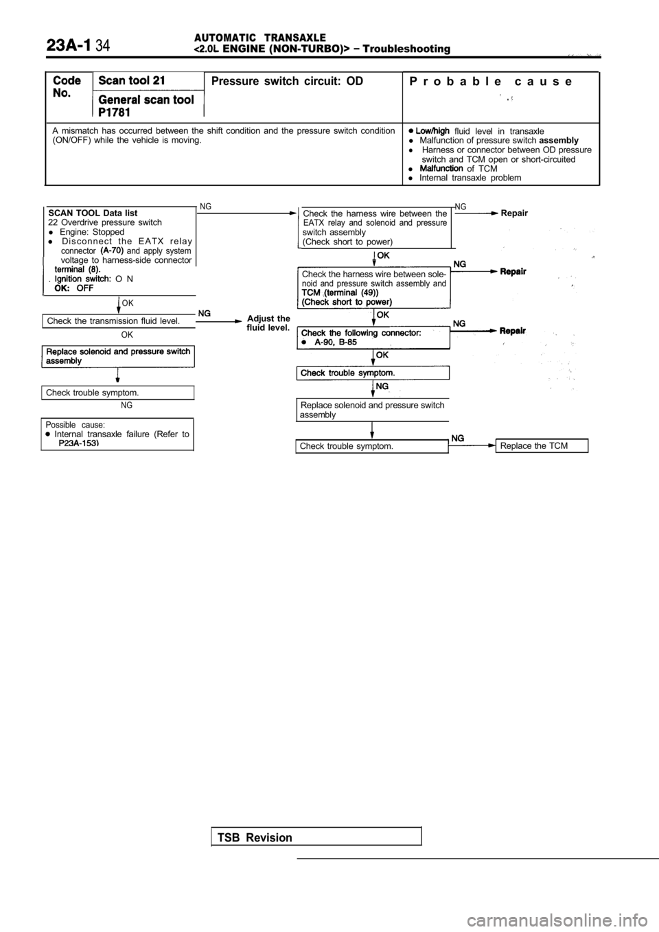
34AUTOMATIC TRANSAXLE ENGINE (NON-TURBO)> Troubleshooting
Pressure switch circuit: OD
A mismatch has occurred between the shift condition and the pressure switch condition
(ON/OFF) while the vehicle is moving.
SCAN TOOL Data list
NG
22 Overdrive pressure switch l Engine: Stopped
l D i s c o n n e c t t h e E A T X r e l a y
connector and apply systemvoltage to harness-side connector
. O N
OK
Check the transmission fluid level.
OK
Replace solenoid and pressure switch
Check trouble symptom.
NG
Possible cause: Internal transaxle failure (Refer to
Adjust the
fluid level.
P r o b a b l e c a u s e
.
fluid level in transaxle
l Malfunction of pressure switch assembly
lHarness or connector between OD pressure
switch and TCM open or short-circuited
l
of TCM
l Internal transaxle problem
Check the harness wire between the
EATX relay and solenoid and pressureswitch assembly
(Check short to power)
NG Repair
Check the harness wire between sole-noid and pressure switch assembly and
Replace solenoid and pressure switch
assembly
Check trouble symptom.
TSB Revision
Replace the TCM
Page 1144 of 2103

36AUTOMATIC TRANSAXLE
ENGINE (NON-TURBO)> Troubleshooting
Code Scan tool 24Pressure switch cricuit: LRProbable cause
No.General scan tool
A mismatch has occurred between the shift condition
and the pressure switch conditionl
Low/high fluid level transaxle
(ON/OFF) while the vehicle is moving. l
Malfunction of switch l Harness or connector between pressure
switch and TCM open or short-circuited
l Malfunction of TCM
l Internal transaxle problem
SCAN TOOL
list
20 pressure switch
l Engine: Stopped
l D i s c o n n e c t t h e E A T X r e l a y
connector and apply systemvoltage to harness-side connector
terminal (8).
l Ignition switch: ON
OK: OFF
NG Check the harness wire between theEATX relay and solenoid and pressureswitch assembly
(Check short to power)
Hydraulic Possible causes:
l Raise vehicle on hoist lIncorrect transmission fluid levelallowsfrontwheelstoturn.l
Internal transaxle failure (Refer
l Attach oauae to to
l the Replace and pressure
l
Increase speed to1 5 0 01. Take a reading of theclutch pressure.O K : psi)
2. SCAN TOOL list
20 L-R pressure switch
OK: ON Replace the TCM
OK
INTERMITTENT MALFUNCTIONl
Study the DTC information (back-
ground, range of check, setting
condition).l Refer to INTRODUCTION How
to Cope with Intermittent Malfunc-
tion. OK
Check the harness N G Repait and pressure switch assembly andTCM (terminal (10))
(Check short to power)
OK
Check the following connector: .N G Repair
OK
Check trouble
TSB Revision
Replace solenoid and pressure switch
Check trouble symptom.
NG
Replace the TCM
Code Scan tool 25
Pressure switch circuit: Probable cause
No.General scan tool
A mismatch has occurred between the shift condition and the pressure switch conditionl
Low/high fluid level in transaxle
(ON/OFF) while the vehicle is moving. l
Malfunction of pressure switch assembly
l Harness or connector between OD pressure
switch and TCM open or
l Harness or connector between pressure
switch and TCM open or short-circuited
l Malfunction of TCM
Internal transaxle problem
l Carrv out the procedure for code No. 21. (Refer
to
l Carry out the inspection procedure for code No. 24. (Refer
to