Page 112 of 391
INTAKE AND EXHAUST - Exhaust PipeII-5
EXHAUST PIPERllDAM
,le exhaust pipe is supported from the body by
using rubber hangers and, in addition, a flexible pipe
is used at the front exhaust pipe in order to reducethe transmission of vibrations from the exhaust
system to the body.
CONSTRUCTION DIAGRAM
Center exhaust pipeFront exhaust pipe
IPm-muffler
Catalytic converter
Imuffler
IFront exhaust pipeCatalytic convener
Flexible pipe,05AO155
05A0157
Front exhakt pipeCatalytic converter
Page 121 of 391

FUEL SYSTEM -Fuel Supply and Fuel Pressure Control14-9
03Poo4:Diaphragm
from intake
4Fuel from delivery pipe
4m
B(42.7)QQ
2
sl -196 2
(26.4) g
t
$!a d
9
0)Positive5 z‘. pressure
(E.2)
w
FUEL FILTERA high-pressure type filter is installed at the delivery end of the
fuel pump.
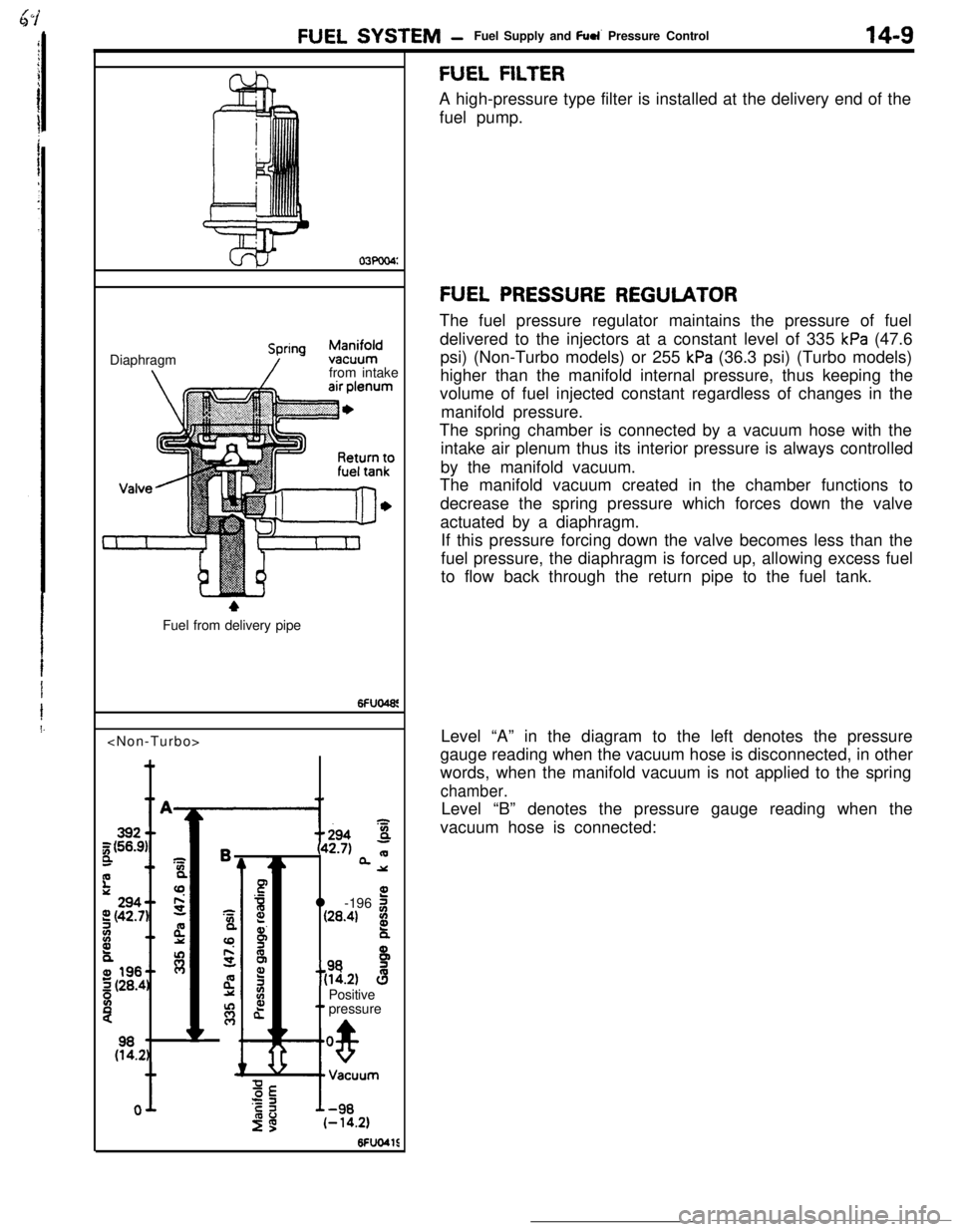
FUEL PRESSURE REGULATORThe fuel pressure regulator maintains the pressure of fuel
delivered to the injectors at a constant level of 335
kPa (47.6
psi) (Non-Turbo models) or 255
kPa (36.3 psi) (Turbo models)
higher than the manifold internal pressure, thus keeping the
volume of fuel injected constant regardless of changes in the
manifold pressure.
The spring chamber is connected by a vacuum hose with the
intake air plenum thus its interior pressure is always controlled
by the manifold vacuum.
The manifold vacuum created in the chamber functions to
decrease the spring pressure which forces down the valve
actuated by a diaphragm.
If this pressure forcing down the valve becomes less than the
fuel pressure, the diaphragm is forced up, allowing excess fuel
to flow back through the return pipe to the fuel tank.
Level “A” in the diagram to the left denotes the pressure
gauge reading when the vacuum hose is disconnected, in other
words, when the manifold vacuum is not applied to the spring
chamber.Level “B” denotes the pressure gauge reading when the
vacuum hose is connected:
Page 128 of 391

14-16FUEL SYSTEM - Sensors
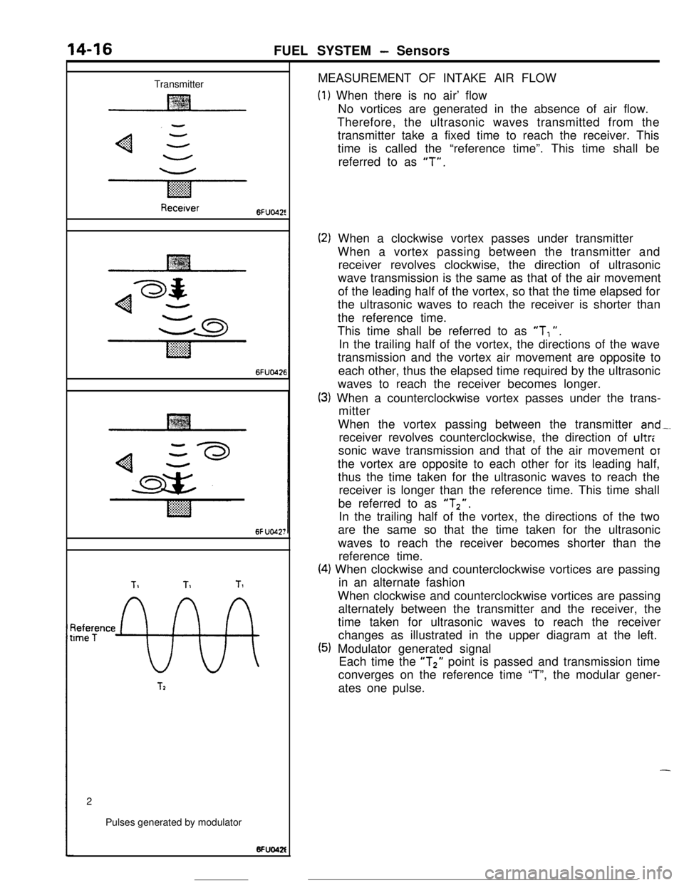
TransmitterMEASUREMENT OF INTAKE AIR FLOW
(1) When there is no air’ flow
No vortices are generated in the absence of air flow.
Therefore, the ultrasonic waves transmitted from the
transmitter take a fixed time to reach the receiver. This
time is called the “reference time”. This time shall be
referred to as
“T”.
Recetver6FUo42!
6FUO426
6f UO42;
TIT1Tl
~tee;ence
9%
T22
Pulses generated by modulator
(2) When a clockwise vortex passes under transmitter
When a vortex passing between the transmitter and
receiver revolves clockwise, the direction of ultrasonic
wave transmission is the same as that of the air movement
of the leading half of the vortex, so that the time elapsed for
the ultrasonic waves to reach the receiver is shorter than
the reference time.
This time shall be referred to as
“T, “.
In the trailing half of the vortex, the directions of the wave
transmission and the vortex air movement are opposite to
each other, thus the elapsed time required by the ultrasonic
waves to reach the receiver becomes longer.
(3) When a counterclockwise vortex passes under the trans-
mitter
When the vortex passing between the transmitter
and-.receiver revolves counterclockwise, the direction of ultr:
sonic wave transmission and that of the air movement
OTthe vortex are opposite to each other for its leading half,
thus the time taken for the ultrasonic waves to reach the
receiver is longer than the reference time. This time shall
be referred to as
“Tz”.In the trailing half of the vortex, the directions of the two
are the same so that the time taken for the ultrasonic
waves to reach the receiver becomes shorter than the
reference time.
(4) When clockwise and counterclockwise vortices are passing
in an alternate fashion
When clockwise and counterclockwise vortices are passing
alternately between the transmitter and the receiver, the
time taken for ultrasonic waves to reach the receiver
changes as illustrated in the upper diagram at the left.
(5) Modulator generated signal
Each time the “T2” point is passed and transmission time
converges on the reference time “T”, the modular gener-
ates one pulse.
-
Page 130 of 391

14-18FUEL SYSTEM - Sensors
tBAROMETRIC PRESSURE SENSOR
Barometnc rxessure sensor
EC1537
Barometncpressure sensor
Enginecontrol unit
1OFUO576
/
760 (30)Barometric pressure mmHg
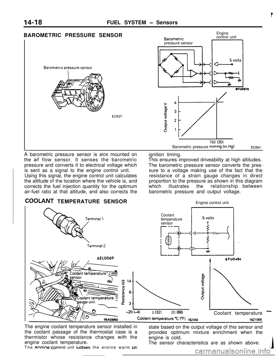
(in.Hg)EC1551A barometric pressure sensor is
alas mounted on
the
aif flow sensor. It senses the barometric
pressure and converts it to electrical voltage which
is sent as a signal to the engine control unit.
Using this signal, the engine control unit calculates
the altitude
of.the location where the vehicle is, and
corrects the fuel injection quantity for the optimum
air-fuel ratio at that altitude, and also corrects the
COOLANT TEMPERATURE SENSOR
Terminal 26EL0069ignition timing.
This ensures improved driveability at high altitudes.
The barometric pressure sensor converts the pres-
sure to a voltage making use of the fact that the
resistance of a strain gauge changes in direct
proportion to the pressure as shown in this diagram
which
illustratestherelationship between
barometric pressure and output voltage.
Engine control unit
Coolanttemperature
sensor
-a
Tg-I
h-esI
*
5 volts
LizIdr
tSFUOLSL
L0 (32120 (68)Coolant temperature -The engine coolant temperature sensor installed in
the coolant passage of the thermostat case is a
thermistor whose resistance changes with the
engine coolant temperature.
The
annine control unit iudoes the enoine warm UDstate based on the output voltage of this sensor and
provides optimum mixture enrichment when the
engine is cold.
The sensor characteristics are as shown above..:I
Page 170 of 391
._ ..-
14-58
.-FUEL SYSTEM
- Accelerator Components
-7
ACCELERATOR COMPONENTSRlUUAAThe accelerator is the cable type, and the pedal is
the suspended type.
A nylon bushing is installed on the end of the
accelerator cable, preventing contact noise
be-tween the cable and accelerator arm from beinggenerated.
In addition, the accelerator pedal switch, which is
used as a control sensor on models with the4-speed NT, is equipped at the pedal support
member.
CONSTRUCTION DIAGRAM
Accelerator cable
Accelerator pedal
switch
bushing
\Accelerator
cableAccelerator
ahmember
Accelerator
Accelerator
pedal
Page 171 of 391
FUEL SYSTEM -Auto-cruise Control System14-59AUTO-CRUISE CONTROL SYSTEMRIIPA&A
using the auto-cruise control system, the vehicle
oar-rbe maintained at a constant driving speed
[between 40 km/h (25 mph) or higher and 145 km
(90 mph) or lower], as selected by the driver,
without using the accelerator pedal.The actuator is the DC motor-driven type for a high
degree of adherence to the set speed. A flexiblesupport system is used for installation of the
actuator in order to prevent the transaxle of body
vibrations to the actuator.
CONSTRUCTION DIAGRAM
control switchOJAO2SS
Accelerator
Actuator
ab’ea\ A
Inhibitor switch
Vehicle speed sensor
(reed switch)
Accelerator cab1e.A/IClutch switch
/Accelerator pedal switch IStop light switch
Page 172 of 391
Page 173 of 391
F
FUEL SYSTEM -Auto-cruise Control System'l4-61
AUTOCRUISE CONTROL UNIT
Je auto-cruise control unit incorporates a micro-computer which provides the set coast, resume,
acceleration, cancel, low-speed limitation,
high-speed limitation, overdrive OFF control, and
auto-
matic cancellation functions. The microcomputer
inputs signals from the vehicle speed sensor and
the switches, and outputs Control signals to the
actuator’s DC motor, the electromagnetic clutch,and the automatic
.transaxle (4 A/T) control unit in
accordance with the programming (software) of themicrocomputer.
CONTROL LOGIC BLOCK DIAGRAM
--
Auto-cruise control UnitIgnitionswitcha.-.
I
Input interface circuit
piz7q.f~~
I
L
Micro-
computer
jutput interface circuitIr--lI----
--7I IActuatorI
Electromagnetic
clutch coil
OD-OFF out-
put circuit
NC: Normally closed