Page 197 of 391
- ._ ____.-.-- -.._ -.-.- - ..__-
17-4 REAR SUSPENSION tZWD>- Wheel Alignment / Anti-lift Geometry
-Wheel center lineWHEEL ALIGNMENTRl
The camber and toe-in have been set to the optimum value, in
the same way as for front-wheel alignment. in particular, the
camber is negative camber, thus improving straight-ahead
driving at high speed.
ANTI-LIFT GEOMETRY
Rl7DAAAOrdinarily, when the brakes are applied, the load is
mc1toward the front of the vehicle as the result of inertial force,
c .Jthis causes the rear end of the vehicle to try to rise upward, but
this is counteracted by the use ‘of the trailing-arm type of
suspension which forms a suspension link design with a high
“anti-lift” effect.
In other words, braking force
F is divided into force compo-
nents
F, and F,; F, acts in the direction that contracts the rear
spring, so that the“lift” can be suppressed.
Page 247 of 391

I,?+7_-AUTOMATIC TRANSAXLE
- Transaxle Mechanism21-23
I IRS SP175003TC
: Torqueconverter
DC : Damper clutchCl : Front clutch
tPlanetan/
gear set
C2 : Rear clutchW : End clutchBl. : Kickdown brake82 : Low/reverse brake
OWC : One-way clutch
FS : Forward sun gearRS : Reverse sun gear
SP : Short pinion
LP : Long pinionAG : Annulus gearTRANSAXLE MECHANISM
fQlEMhGENERAL DESCRIPTION
The power train is composed of the torque-converter section
(which transfers the power from the engine to the transaxle)
and the shifting mechanism (which functions to provide the
most appropriate
rotational speed).
The damper clutch is installed in the torque-converter section.
and functions to reduce the ainount of power loss resulting
from slippage of the torque-converter.
The shifting mechanism is composed of three sets of multiple-
disc type clutches, as well as one set each of a multiple-disc
type brake and band brake, and a one-way clutch and a
Ravigneaux-type planetary gear set. The three sets of clutches
are the elements for control of the input to the planetary gear
set, and the two sets of brakes and the one-way clutch are the
elements for holding each part of the planetary gear set, or for
obstructing rotation.
As a result of the operation on these elements, the shifting
ratio that corresponds to the driving conditions is obtained by
regulating from what point of the
planetan/ gear set there will
be input, and where holding will be done.
Under what circumstances which elements will be activated is
as described in the table (“ELEMENT IN USE AT EACH
POSITION OF SELECTOR LEVER”) below.
ELEMENT IN USE AT EACH
POSITtON OF SELECTOR LEVER
S ylele~rOverdriveGearGearEngineParkingClutches
Brakescontrolmecha-
positionswitchpositionratiostartnismCl c2C3 OWC Bl 82
PNeutral-Possible0
RReverse2.17600
NNeutral-Possible
First
2.8460a
Second1.581l0DON
Third1 .ooo000
e
Fourth0.68500
First2.84600
DOFFSecond1.581ll
Third1 .ooo000
First2.846002
Second1.5810l
LFirst2.8460l
Page 269 of 391

‘4) Once the operation is step (2) is completed, the
hydraulic control device functions by hydraulic
pressure force to change the state of the
clutches and brakes to accomplish the gear
shifting. To minimize the shock that would
otherwise be produced during gear shifting,
hydraulic pressure is controlled during the gear
shifting period by the “duty control” of the
pressure control solenoid valve. The duty control
is explained later.
‘HYDRAULIC PRESSURE CONTROL DURING
SHFIING(1) The hydraulic pressure that functions during
gear shifting to engage the clutches and apply
the brakes is regulated by the pressure control
valve, The hydraulic pressure that works on the
pressure control valve is further regulated by the
pressure control solenoid valve which functions
under the control of the transaxle control unit.
The transaxle control unit controls the solenoid
valve through the duty control, thus providing
appropriate regulation of the hydraulic pressure.
(2)
(3)
(4)The transaxle control unit decides the timing of
the gear shifting period (during which ‘it per-
forms hydraulic pressure control for gear shift-
ing) according to the change in the kickdown
drum rotating speed that it detects. The unit
identifies the time just before the kickdown
brake is applied and uses that as the timing for
initiating control of the hydraulic pressure which
is to be applied to the kickdown brake.
When the transaxle is cold, the fluid viscosity is
high, causing slower oil pressure response. in
such conditions, the transaxle control unit pro-
vides a correction for the oil pressure by
changing the control duty of the pressure control
solenoid valve.
This control is performed when the fluid temper-
atures as indicated by the oil temperature
sensor is lower than
60°C (140°F).After the engine has been started and the
vehicle is inmotion, the transaxle
continues torefine its performance
est possiblegear shifting.control unit
for smooth-
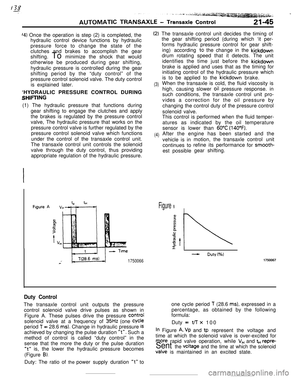
tHFigure B
- Duty(%)
17500661750067
Duty ControlThe transaxle control unit outputs the pressureone cycle period
T (28.6 ms), expressed in a
control solenoid valve drive pulses as shown inpercentage, as obtained by the following
formula:
Figure A. These pulses drive the pressure
COrmIsolenoid valve at a frequency of
35Hz (one Cycleperiod
T = 28.6 ms). Change in hydraulic pressure iSDuty =t/-r x 100
achieved by changing the pulse duration
“t”. Such aIn Figure A, Vp and tp represent the voltage and
method of control is called “duty control” in thetime at which the solenoid valve is over-excited for
sense that the more the duty or the pulse duration
more rapid valve operation, while V,, and t+., repre-
“t” is, the lower the hydraulic pressure becomesSent the v,oltage and the time at which the solenoid(Figure
B).Valve is maintained in an excited state.
Duty: The ratio of the power supply duration
“t” to