Page 112 of 677

SUPPLEMENTAL SERVICE INFORMATION, FUEL SYSTEM Fl
SUPPLEMENTAL SERVICE INFORMATION
The following points in this section are changed in comparison with Mazda 323 Workshop Manuals
(I 203-I U-89F, 1204-I O-89F, I2061 O-89F).
fuel tank
l Removal I Inspection I Installation
4x4 control unit (Fuel pump control unit)
l Inspection procedure added
l Replacement procedure added
Transfer pump switch
l Inspection procedure added
l Replacement procedure added
Transfer pump
l Inspection procedure added
l Replacement procedure added
Exhaust system components
l Removai I Inspection I installation 93GOF? -706
FUELSYSTEM
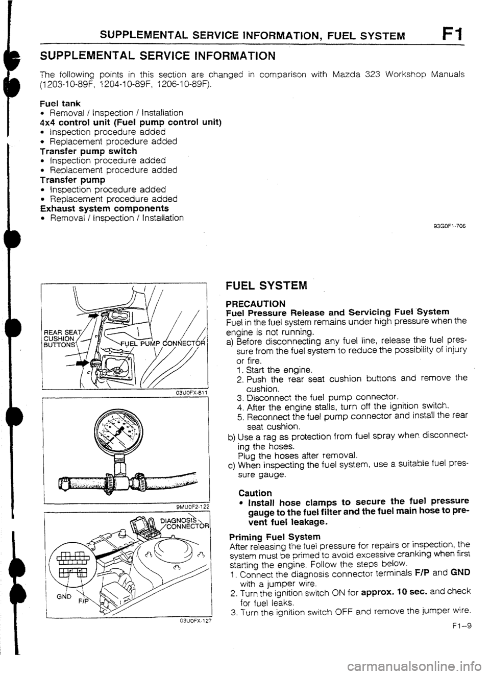
PRECAUTION
Fuel Pressure Release and Sewicing Fuel System
Fuel in the fuel system remains under high pressure when the
engine is not running.
a) Before disconnecting any fuel line, release the fuel
pres-
sure from the fuel system to reduce the possibility of injury
or fire.
1. Start the engine.
2. Push the rear seat cushion buttons and remove the
cushion.
3. Disconnect the fuel pump connector.
4. After the engine stalls, turn off the ignition switch.
5. Reconnect the fuel pump connector and install the rear
seat cushion.
b) Use a rag as protection from fuel spray when disconnect-
ing the hoses.
Plug the hoses after removal.
c> When inspecting the fuel system, use a suitable fuel pres-
sure gauge.
Caution
l Install hose clamps to secure tile fuel pressure
gauge to the fuel filter and the fuel main hose to pre-
vent fuel leakage.
Priming Fuel System
After releasing the fuel pressure for repairs or inspection, the
system must be primed to avoid excessive cranking when first
starting the engine. Follow the
steps below.
I. Connect the diagnosis connector terminals F/P and GND
with a jumper wire.
2. Turn the ignition switch ON for approx. IO sec. and check
for fuel leaks.
3. Turn the ignition switch OFF and remove the jumper wire.
Fl-9
Page 117 of 677
TRANSFER PUMP CONTROL SYSTEM
2. Remove the service hole cover of the transfer pump.
3. Disconnect the transfer pump connectors.
4. Disconnect the fuel hose.
5. Remove the transfer pump.
Caution
l Install a new seal rubber.
6. Install in the reverse order of removal.
03UOFX-626
Disassembly / Assembly
Caution
l Prevent contaminants from entering the transfer pump,
I. Disassemble in the order shown in the figure.
2. Assemble in the reverse order of disassembly.
3. Verify that the transfer pump operates
correctly after assembling it.
EAL RUBBER, REPLACE
1 . Fuel filter
2. Rubber mount
3. Transfer pump 4. Fuel hose
5. Transfer pump
switch
Ft-14
Page 123 of 677
SOLENOID VALVE
CHECK VALVE
r----+ (PURGE CONTROL)
CHiRCOAL
I CANISTER
INTERCOOLER 11 ’ 1 ‘I A-4
II II -
AIR , BYPASS
II ,.-ok----,/ ,CHECK VALVE
(TWO-WAY)
1-1
---II
-d KNO&
II II I I II VALVE
VALVE
THERMOSENSOR
c
I 31c
SENSOR 1 k---k FUEL FILTER
TRANSFER
PUMP
WASTEGATE 7
II t I III TURtiOCHARGERI~
I SOLENOID I II - i 1 WASTFGATF II I
AlOCI fuAl RAlz-rCD
VALVE
le-SIGNAL* -
EJ 0
G-SIGNAL-
DISTRIBUTOR
CATALYTIC CONVERTER ftl”FLLt”” IVIL I =r,
(WITH INTAKE THERMOSENSOR)
*TO ENGINE CONTROL UNIT
Page 150 of 677
![MAZDA 232 1990 Workshop Manual Suplement TROUBLESHOOTING GUIDE F2
]sTFP 1 INSPECTION ACTION
I
Aerator depressed ful ty
rminal 1F voltage
: SELF TEST
ignition timing: BTDC 10 = I*
8 Check for correct fuel line pressure at idle’ Yes C MAZDA 232 1990 Workshop Manual Suplement TROUBLESHOOTING GUIDE F2
]sTFP 1 INSPECTION ACTION
I
Aerator depressed ful ty
rminal 1F voltage
: SELF TEST
ignition timing: BTDC 10 = I*
8 Check for correct fuel line pressure at idle’ Yes C](/manual-img/28/57056/w960_57056-149.png)
TROUBLESHOOTING GUIDE F2
]sTFP 1 INSPECTION ACTION
I
Aerator depressed ful ty
rminal 1F voltage
: SELF TEST
ignition timing: BTDC 10 = I*
8 Check for correct fuel line pressure at idle’ Yes Check if fuel line pressure decreases
when accelerating quickly
Fuel line
pressure: 265-314 kPa (2.7-3.2 kg/cm’, 38-46 psi)
(vacuum hose to pressure regulator dis-
connected) 4 If decreases check fuel pump
maximum pressure*
If OK, check fuel line and filter for
clogging
4 If no decrease, go to next step
NO Low pressure
Check fuel irne pressure while pinching
fuel return hose
4 If fuel line pressure quickly in-
creases, check pressure
regulator' e If fuel lrne pressure gradually in-
creases, check for cloggrng be-
tween fuel pump and pressure
regulator
If not clogged, check fuel pump
maximum pressure* High pressure
Check of fuel return line is ctogged
4 If OK, replace pressure regulator
e If not OK. replace
- _
* Refer to 323 Workshop Manual
[I 203-1 O-89F (Europe), or 1204-lU-89F (Australra)].
FZ-33
Page 155 of 677
F2 TROUBLESHUOTtNG GUIDE
check fuel pump maxi-
fuel line and filter for
pump and pressure
High pressure
Check if fuel line is clogged
II. Measure resistance
r--- ---_--es-,
DAMAGE AND
DETERIORATION
* Refer to 323 Workshop Manual f1203-1 O-89F (Europe) 12041U-89F (Australia)].
F2-38
Page 167 of 677

F2 FUEL SYSTEM
FUEL
SYSTEM
PREPARATlON
SST
49 LO18 901
Injector checker For
lnsgectlon of
injector
93GOF2.770
9MUOF2-722
03UOFX-7 27
F2-50
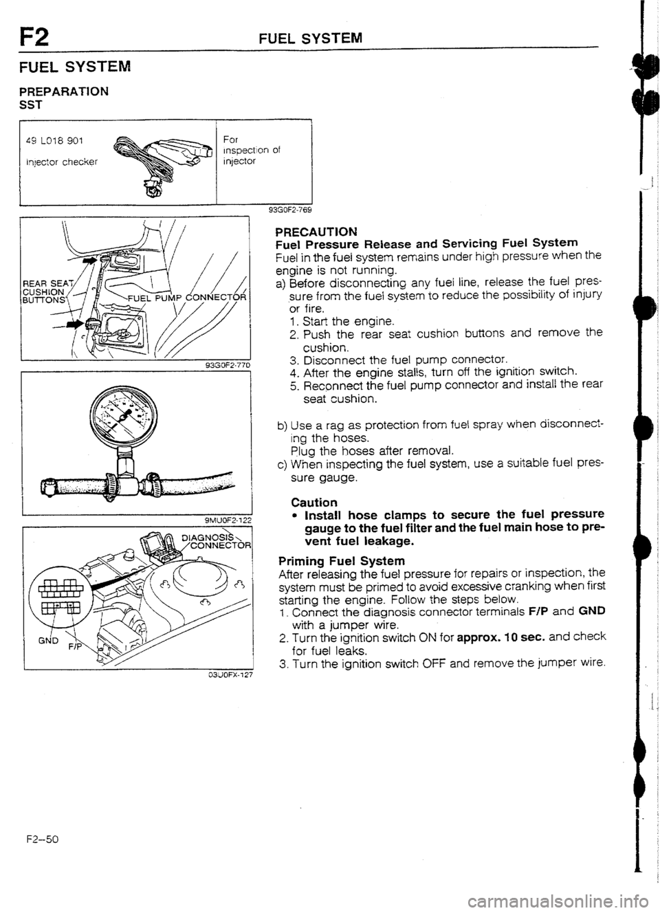
PRECAUTION
Fuel Pressure
Release and Servicing Fuel System
Fuel in the fuel system remains under high pressure when the
engine is not running.
a) Before disconnecting any fuel line, release the fuel pres-
sure from the fuel system to reduce the possibility of injury
‘or fife,
1. Start the engine.
2. Push the rear seat cushion buttons and remove the
cushion,
3. Disconnect the fuel pump connector.
4. After the engine stalts, turn off the ignition switch.
5. Recpnnect the fuel pump connector and install the rear
seat cushion.
b) Use a rag as protection from fuel spray when disconnect-
ing the hoses.
Plug the hoses after
removal.
c) When inspecting the fuel system, use a suitable fuel pres-
sure gauge.
Caution
l Install hose clamps to secure the fuel pressure
gauge to the fuel filter and the fuel main hose to pre-
vent fuet leakage.
Priming Fuel System
After releasing the fuel pressure for repairs or inspection, the
system must be primed to avoid excessive cranking when first
starting the engine. Follow the steps
below.
1. Connect the diagnosis connector terminals F/P and GND
with a jumper wire.
2. Turn the ignition switch
ON for approx. 10 set, and check
for fuel leaks.
3. Turn the ignition switch OFF and remove the jumper wire.
Page 172 of 677
FUEL SYSTEM F2
2. Remove the service hole cover of the transfer pump.
3. Disconnect the transfer pump connectors.
4. Disconnect the fuel hose,
5.
Remove the transfer pump.
6. Install in the reverse order of removal. Caution
l Install a new seat rubber.
03UOFX-826
Disassembly I Assembly
Caution
l Prevent contaminants from entering the transfer pump.
1. Disassemble in the order shown in ,the figure.
2. Assemble in the reverse order of disassembly.
3. Verify that the transfer pump operates correctly after assembling it.
HOSE, REPLACE
@
1. Fuel filter
2. Rubber mount
3. Transfer pump 4. Fuel hose
5. Transter pump switch assembly
93GOF2-77:
FZ-55