Page 13 of 30

INTRODUCTION AND MASTER TROUBLESHOOTING - t+mwtions Before Service ‘I3
DOING SERVICE WORK IN GROUPS OF TWO OR
MORE TECHNICIANS
If the service work is to be done by two or more technicians
working together, extra caution must be taken.
NOTE ON INSTALLATION OF RADIO EQUlPM$ihl-
The computers of the electronic control system has been
designed so that external radio waves will not interfere with
their operation.
However, if antenna or cable of amateur transceiver etc. is
routed near the computers, it may affect the operation of the
computers. even if the output of the transceiver is no more
than 25W.
To protect each of the computers from interference by
transmitter (hum, transceiver, etc.). the following should be
observed.
1. Install the antenna on the roof or rear bumper.
2. Because radio waves are emitted from the coaxial cable of
the antenna, keep it 200 mm (8 in.) away from the
computers and the wiring harness. If the cable must cross
the wiring harness, route it so that it runs at right angles to
the wiring harness.
3. The antenna and the cable should be well matched, and
the standing-wave ratio” should be kept low.
4. A transmitter having a large output should not be installed
in the vehicle.
5. After installation of transmitter, run the engine at idle, emit
radio waves from the transmitter and make sure that the
engine is not affected.
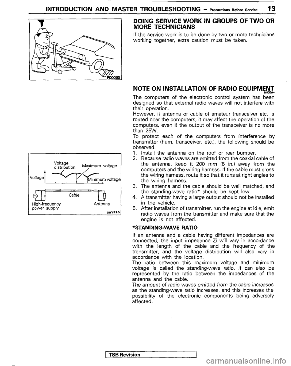
*STANDING-WAVE RATIO
If an antenna and a cable having different impedances are
connected, the input impedance Zi will vary in accordance
with the length of the cable and the frequency of the
transmitter, and the voltage distribution will also vary in
accordance with the location.
The ratio between this maximum voltage and minimum
voltage is called the standing-wave ratio. It can also be
represented by the ratio between the impedances of the
antenna and the cable.
The amount of radio waves emitted from the cable increases
as the standing-wave ratio increases, and this increases the
possibility of the electronic components being adversely
affected.
1 TSB Revision
I
Page 14 of 30
,’ i 1;
h-J ” ^ .
14 Treatment Before I INTRODUCTION AND MASTER TROUBLESHOOTING - AftertheFotiingofastmsm
TREATMENT BEFORE/AFTER THE FORD-
ING OF A STREAM
INSPECTION AND SERVICE BEFORE FORDING
A STREAM NOW%-
Vehicles which are driven through water, or which may
possibly be driven through water, should be subjected to the
following inspections and maintenance procedures in ad-
vance.
e Seal the speedometer cable with a water-resistant grease ~_
or tape.
a Inspect the dust boots and breather hose for cracks or
damage, and replace them if cracks or damage are found.
,- . 1^. dometer cable 1
Steering joint assembly
/ 1 Drive shaft boot -\l(. ‘/ Torsion bar dust cover 1 Breath& hose==
OOW528
( TSB Revision -
Page 16 of 30
16 Treatment Before I INTRODUCTION AND MASTERTROUBLESHOOTING - AftertheFordingofaStream
INSPECTION AND SERVICE AFTER FORDING A
STREAM
After fording a stream, check the following points. If abnormal
condition is evident, clean, replace or lubricate.
= Check for water. mud. sand. etc. in the rear brake drum.
clutch housing, &tarte; mot&, brake pipe and fuel pipe:
Check for water in the fluid or oil inside the front
differential. rear differential, transmission and transfer
case.
Apply grease to the lubricating points of the front suspen-
sion, steering linkage and propeller shaft.
Check all boots and breather hoses for cracks and
damage.
rTSB Revi
Page 18 of 30

.$i ~[ r
18 INTRODUCTION AND MASTER TROUBLESHOOTING - Towing and Hoisting
HOISTING
POST TYPE
Special care should be taken when raising the vehicle on a
frame contact type hoist. The hoist must be equipped with
the proper adapters in order to support the vehicle at the
proper locations. (Shown in the illustration)
Conventional hydraulic hoists may be used after determining
that the adapter plates will make firm contact with the side ._
frame.
FLOOR JACK
A regular floor jack may be used under the front crossmember
or rear axle housing.
Caution
1. A floor jack must never be used on any part of the
underbody.
2. Do not attempt to raise one entire side of the vehicle by
placing a jack midway between front and rear wheels.
This practice may result in permanent damage to the
body.
EMERGENCY JACKING
Jack receptacles are located at the No. 2 crossmember and .
rear axle housing to accept the jack supplied with the vehicle
for emergency road service. Always block the opposite wheels
and jack only on a level surface.
FRAME CONTACT SUPPORT LOCATIONS
1,175 mm (46.3 in.)
Wheel base
2.350 mm (92.5 in.) Sectlon A-A
NOTE
The
locations of the support point shown as Section A-A are
the same as those of the twin post hoist shown in the next
paw.
1 TSB Revision
I -