Page 13 of 30

INTRODUCTION AND MASTER TROUBLESHOOTING - t+mwtions Before Service ‘I3
DOING SERVICE WORK IN GROUPS OF TWO OR
MORE TECHNICIANS
If the service work is to be done by two or more technicians
working together, extra caution must be taken.
NOTE ON INSTALLATION OF RADIO EQUlPM$ihl-
The computers of the electronic control system has been
designed so that external radio waves will not interfere with
their operation.
However, if antenna or cable of amateur transceiver etc. is
routed near the computers, it may affect the operation of the
computers. even if the output of the transceiver is no more
than 25W.
To protect each of the computers from interference by
transmitter (hum, transceiver, etc.). the following should be
observed.
1. Install the antenna on the roof or rear bumper.
2. Because radio waves are emitted from the coaxial cable of
the antenna, keep it 200 mm (8 in.) away from the
computers and the wiring harness. If the cable must cross
the wiring harness, route it so that it runs at right angles to
the wiring harness.
3. The antenna and the cable should be well matched, and
the standing-wave ratio” should be kept low.
4. A transmitter having a large output should not be installed
in the vehicle.
5. After installation of transmitter, run the engine at idle, emit
radio waves from the transmitter and make sure that the
engine is not affected.
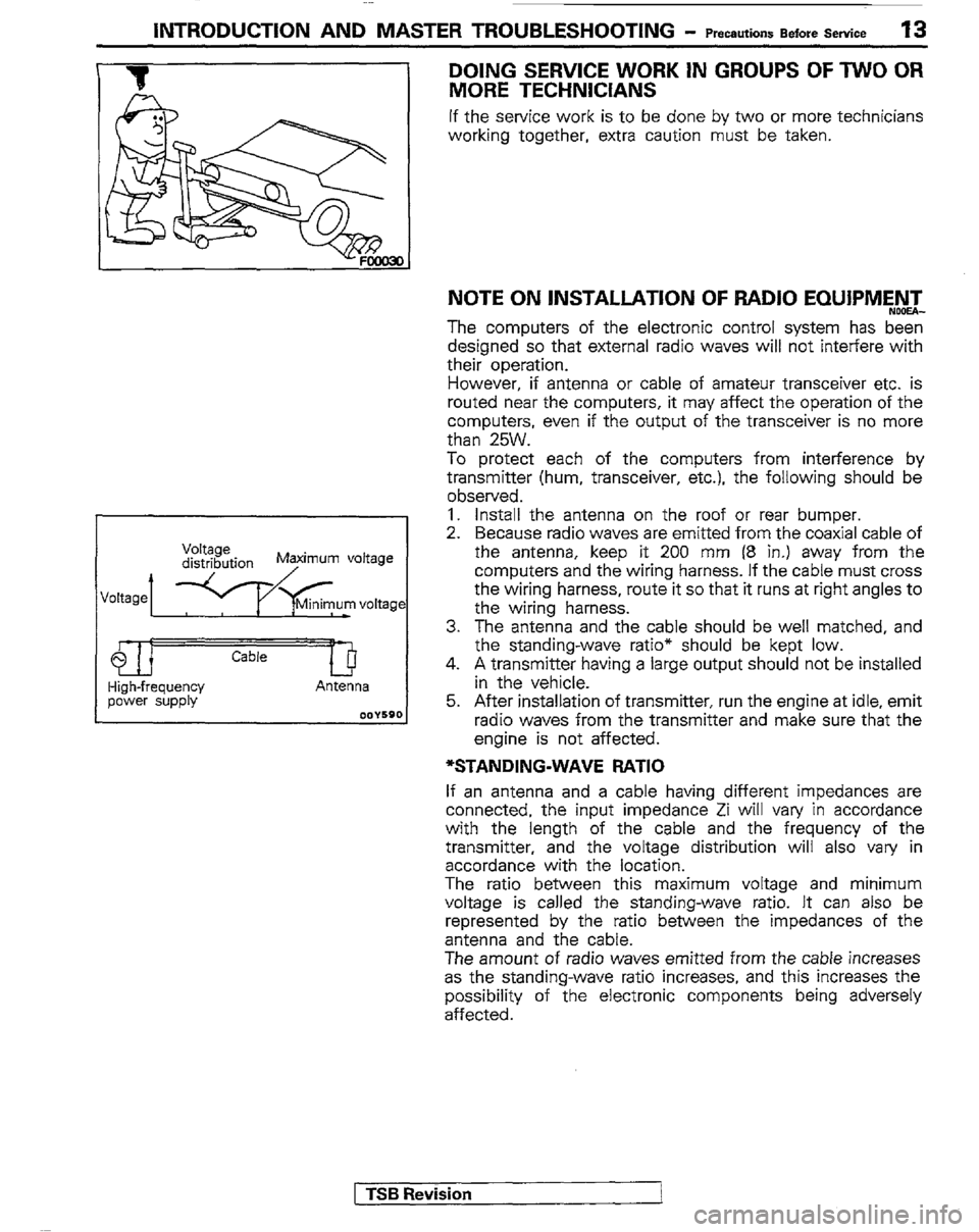
*STANDING-WAVE RATIO
If an antenna and a cable having different impedances are
connected, the input impedance Zi will vary in accordance
with the length of the cable and the frequency of the
transmitter, and the voltage distribution will also vary in
accordance with the location.
The ratio between this maximum voltage and minimum
voltage is called the standing-wave ratio. It can also be
represented by the ratio between the impedances of the
antenna and the cable.
The amount of radio waves emitted from the cable increases
as the standing-wave ratio increases, and this increases the
possibility of the electronic components being adversely
affected.
1 TSB Revision
I
Page 19 of 30
INTRODUCTION AND MASTER TROUBLESHOOTING - Towing and Hoisting 19
LIFTIYG AND JACKING SUPPORT LOCATIONS
<2.6L Engine> <2.6L Engine>
<3.OL Engine> <3.OL Engine>
C Twin post hoist C Twin post hoist
m Floor jack m Floor jack
@ @ Emergency jacking (jack supplied with the vehicle) Emergency jacking (jack supplied with the vehicle)
TSB Revision TSB Revision
Page 21 of 30

INTRODUCTION AND MASTERTROUBLESHOOTING - GeneralDataandSpecmcations 21
L042G L141G
TNSL FM TNJL F/H
TRJL F/H TRUL F/H
Engine
Model No. G54B 6672 6672 6672
Type In-line OHC V-type, OHC V-type, OHC
V-type, OHC
Number of cylinders 4 6 6 6
Bore 91.1 mm(3.59in.j 91.1 mm(3.59in.j 91.1 mm(3.59in.) 91.1 mm(3.59in.
Stroke 98.0 mm (3.86 in.) 76.0 mm (2.99 in.) 76.0 mm (2.99 in.) 76.0 mm (2.99 in.
Piston displacement 2,555 cm3 2,972 cm3 2,972 cm3 2,972 cm3
(155.9 cuin.) (181.4cu.in.) (181.4cu.in.) (181.4 cuin.)
Compression ratio 8.7 8.9 8.9 8.9
Firing order 1-3-4-2 1-2-3-4-5-6 I -2-345-5 1-2-3-4.5-8
Basic ignition timing 7”BTDC 22” 5”BTDC 22” 5”BTDC i 2” 5”BTDC +-2”
Transmission &transfer case
Model No. KM145 V5MTl KM148 KM148
Type S-speed manual 5-speed manual &peed automatic &peed automatic
Gear ratio
Transmission 1st 3.967 3.918 2.826 2.826
2nd 2.136 2.261 1.493 1.493
3rd 1.360 1.395 1 .ooo 1.000
4th 1 .ooo 1.000 0.688 0.688
5th 0.856 0.829 -
Reverse 3.587 3.925 2.703 2.703
Transfer case High 1 .ooo 1 .ooo 1 .ooo 1 .ooo
Low 1.944 1.925 1.925 1.925
Final ring ratio gear 4.625 4.625 4.625 4.625
Clutch
Type Dry single disc & Dry single disc & -
diaphragm spring diaphragm spring
Chassis
Tire size
Front suspension
Type
Rear suspension
Type
Brakes
Type Front
Rear P225ff 5Rl5 P235ff5Rl5
independent Independent double-wishbone
double-wishbone
Rigid axle Rigid axle
Disc Disc
Drum Drum (Leading and trailing)
(Leading and trailing)
Power steering
Gear type
Gear ratio
Fuel tank capacity Integral type Integral type (Recirculating ball nut)
(Recirculating ball nut)
16.4 16.4
liters (gals.) 60 (15.9) 75 (19.8)
[ TSB Revision
Page 24 of 30

24 INTRODUCTION AND MASTER TROUBLESHOOTING - WasterTroubleshooting Tightening Torque I
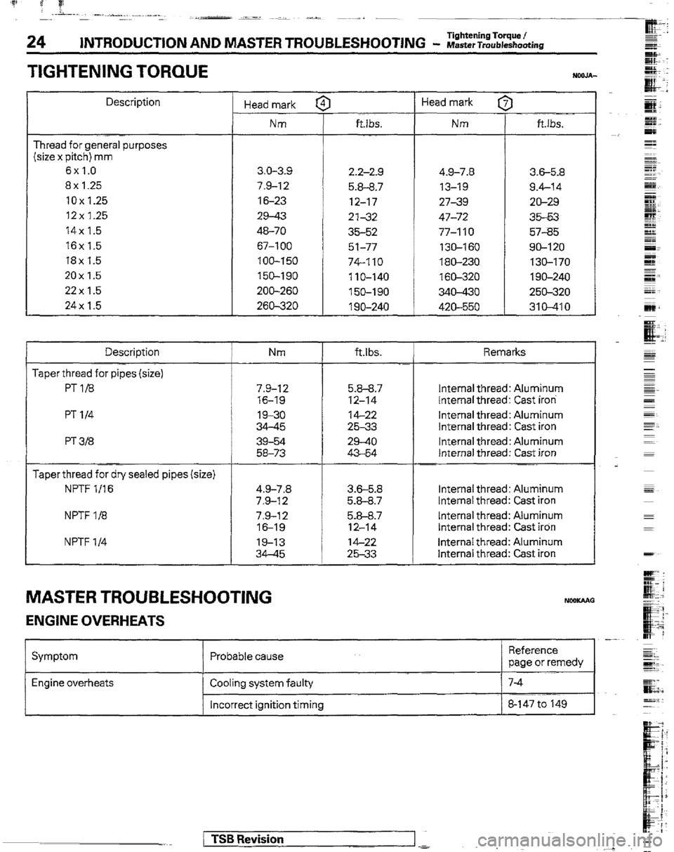
TIGHTENING TORQUE
Description
Thread for general purposes
(size x pitch) mm
6x1.0
8x 1.25
10x1.25
12x 1.25
14x 1.5
16x 1.5
18x 1.5
20x1.5
22x 1.5
24x 1.5
Description
Taper thread for pipes (size)
PT1/8
PT l/4
PT 3B
Taper thread for dry sealed pipes (size)
NF’TF l/16
NPTF l/8
NPTF l/4 Head mark f
Nm
3.0-3-s
7.9-12
16-23
29-43
46-70
67-l 00
100-150
150-190
ZOO-260
269-320 ft.lbs.
2.2-2.9 4.9-7.8
3.6-5.8
5.8-8.7 13-19 9.4-14
12-17 27-39 20-29
2’132 47-72 35-53
35-52 77-110 57-35
51-77 130-160 SO-120
74-110 180-230 130-170
110-140 160-320 1 go-240
150-190 340-430 250-320
1 go-240 420-550 310-410 Head mark [
Nm I
ft.lbs.
Nm ftlbs. Remarks
7.9-I 2 5.9-9.7 Internal thread: Aluminum
76-19 12-14 Internal thread: Cast iron
19-30 14-22 Internal thread: Aluminum
34-45 25-33 Internal thread: Cast iron
39-54 29-40 Internal thread: Aluminum
58-73 43-54 Internal thread: Cast iron
4.9-7.8 3.6-5.8 Internal thread: Aluminum
7.9-12 5.8-8.7 Internal thread: Cast iron
7.9-12 5.8-8.7 Internal thread: Aluminum
16-1s 12-14 Internal thread: Cast iron
19-13 14-22 Internal thread: Aluminum
34-45 25-33 Internal thread: Cast iron
MASTER TROUBLESHOOTING NceKAAO
ENGINE OVERHEATS
Symptom Probable cause -
Reference
page or remedy
Engine overheats Cooling system faulty
Incorrect ignition timing
1 TSB Revision
Page 25 of 30

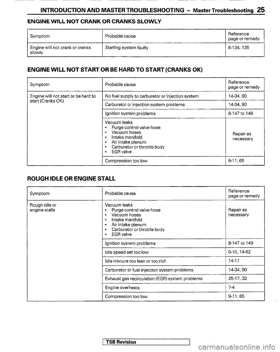
INTRODUCTION AND MASTER TROUBLESHOOTING - Master Troubleshooting 25
ENGINE WILL NOT CRANK OR CRANKS SLOWLY
Symptom
Engine will not crank or cranks
slowly Probable cause
Starting system faulty Reference
page or remedy
8-134.135
ENGINE WILL NOT START OR BE HARD TO START (CRANKS OK)
Symptom
Engine will not start or be hard to
start(Cranks OK)
ROUGH IDLE OR ENGINE STALL
Probable cause
No fuel supply to carburetor or injection system
Carburetor or injection system problems
Ignition system problems
Vacuum leaks
- Purge control valve hose
- Vacuum hoses
l intake manifold
- Air intake plenum
l Carburetor or throttle body
l EGRvalve
Compression too low Reference
page or remedy
14-34,90
14-34,90
3-147 to 149
Repair as
necessary
3-11.65
Symptom Probable cause Reference
page or remedy
Rough idle or
engine stalls Vacuum leaks
l Purge control valve hose
l Vacuum hoses
l Intake manifold
l Air intake plenum
l Carburetor or throttle body
l EGRvalve
1 Ignition system problems Repair as
necessary
8-147 to 149
Idle speed set too low 1 O-10.14-62
1~ ~ . Idle mrxture too lean or too rich 14-11
Carburetor or fuel injection system problems
Exhaust gas recirculation (EGR) system problems m-34.90
25-17.32
Engine overheats 7-4
Compression too low 9-11, 65
1 TSB Revision
Page 26 of 30

‘p ? f! .., .-, _-_ ,_- ____ ____ _L(
26 INTRODUCTION AND MASTER TROUBLESHOOTlNG - Master Troubleshooting
ENGINE HESITATES OR POOR ACCELERATION
Symptom Probable cause
Engine hesitates or
poor acceleration
-I
Ignition system problem
Vacuum leaks
l Purge control valve hose
l Vacuum hoses
- intake manifold
l Air intake plenum
* Carburetor or throttle body
l EGRvalve
ENGINE DIESELING
Reference
page or remedy
8-147 to 149
Repair as
necessary
Air cleaner clogged
Fuel line clogged 113.10
1442.99
Carburetor or fuel injection system problem
Auxiliary acceleration pump faulty (cold engine)
Emission control system problem
l EGR system always on
- High-altitude compensation (HAC) system problem
Engine overheats 14-34.90
14-23
25-77.22.32
7-4
Compression too low g-II.65
I Symptom Probable cause I
Reference
page or remedy
I I I I -..
Engine dieseling (runs after
ignition switch is turned off) Carburetor problems
Incorrect ignition timing 14-34
8-14710 149
EXCESSIVE OIL CONSUMPTION
Symptom Probable cause Reference
page or remedy
Excessive oil consumption Oil leak
Positive crankcaseventilation line clogged
Valve stem seal worn or damaged
Valve stem worn
Piston ring worn or damaged Repair as
necessary
o-13
Replace
Replace
9-43
1 TSB Revision