1989 MAZDA 323 ad blue
[x] Cancel search: ad bluePage 17 of 1164

CAUTION GI
9MUGIX-032
9MUGIX-029
Fuse
Replacement
1. When replacing a fuse, be sure to replace it with one of
specified capacity.
If a fuse again fails after it has been replaced, the circuit
probably has a short circuit and the wiring should be
checked.
2. Be sure the negative battery terminal is disconnected be-
fore replacing a main fuse (80A).
3. When replacing a pullout fuse, use the fuse puller supplied
in the fuse box cover.
Wiring Harness
Wiring color codes
Two-color wires are indicated by a two-color code symbol.
The first letter indicates the base color of the wire and the sec-
ond the color of the stripe.
CODE COLOR
B Black
BR Brown
G Green
GY Gray
L Blue
LB Light Blue
LG Light Green CODE COLOR
0 Orange
P Pink
R Red
v Violet
w White
Y Yellow
- -
GI-15
Page 52 of 1164
Bl ON-VEHICLE MAINTENANCE
8 e
93UOlA.08
EX
03UOBl-035
HEAD COVER
)
23UOBl-023
Steps After Installation
1, Connect the negative battery cable.
2. Start the engine and fully warm up.
3. Verify that there is no tappet noise. 2. Install the rocker arm and rocker shaft assembly.
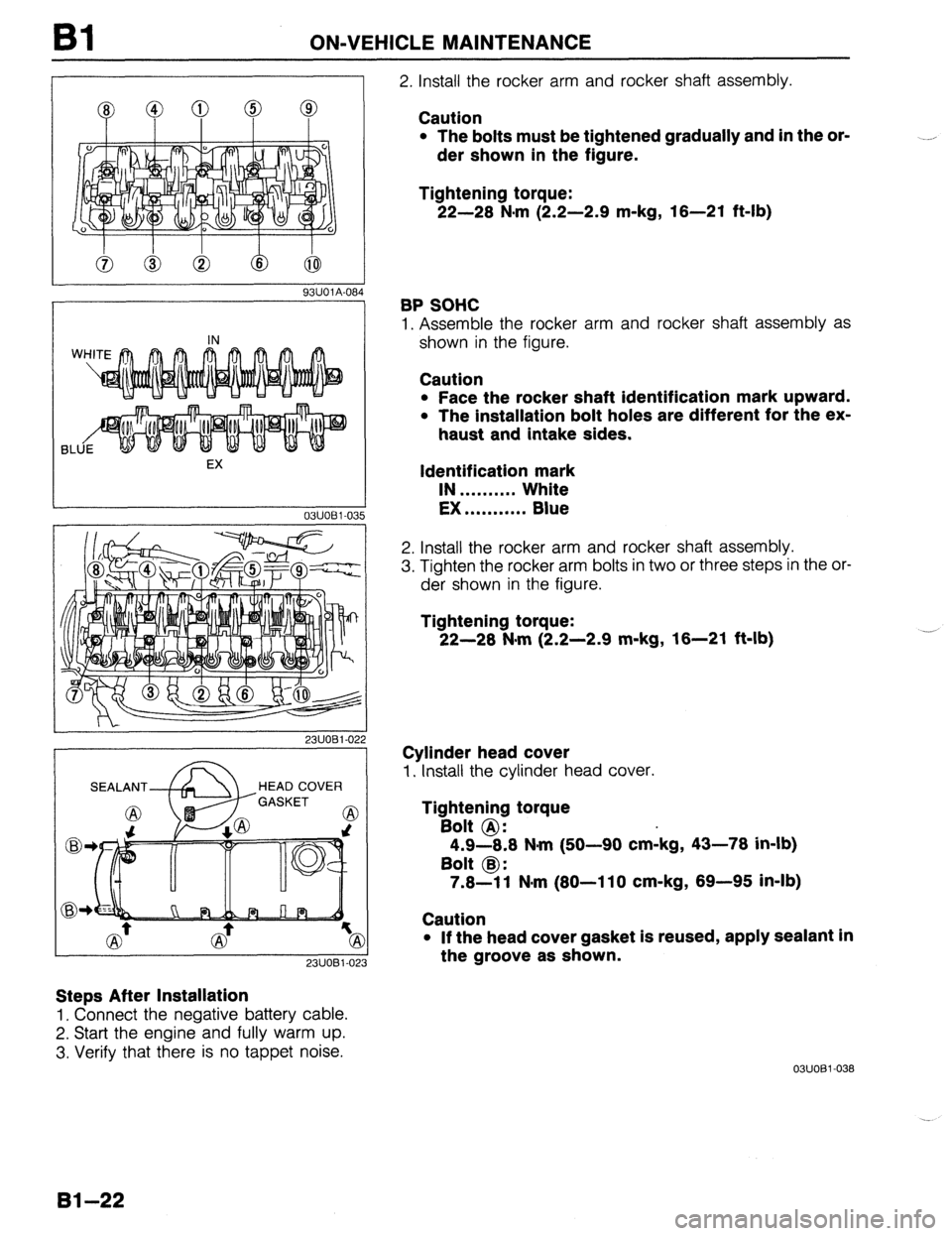
Caution
l The bolts must be tightened gradually and in the or-
der shown in the figure.
Tightening torque:
22-28 N-m (2.2-2.9 m-kg, 18-21 ft-lb)
BP SOHC
1. Assemble the rocker arm and rocker shaft assembly as
shown in the figure.
Caution
l Face the rocker shaft identification mark upward.
l The installation bolt holes are different for the ex-
haust and intake sides.
Identification mark
IN . . . . . . . . . . White
EX . . . . . . . . . . . Blue
2. Install the rocker arm and rocker shaft assembly.
3. Tighten the rocker arm bolts in two or three steps in the or-
der shown in the figure.
Tightening torque:
22-28 Nsrn (2.2-2.9 m-kg, 16-21 ft-lb)
Cylinder head cover
1. Install the cylinder head cover.
Tightening torque
Bolt @:
4.9-8.8 N-m (50-90 cmikg, 43-78 in-lb)
Bolt @:
7.8-l 1 Nnrn (80-l 10 cm-kg, 69-95 in-lb)
Caution
l If the head cover gasket is reused, apply sealant in
the groove as shown.
03UOBl-038
.-
Bl-22
Page 87 of 1164
INSPECTION / REPAIR Bl
-- 05lJOBX-13
.- __--- 0
-_.--__I__
--
05UOBX.131
B6 SOHC
EX
IN
BP SOHC --~ -____
03uoEI-09
--__.
86 SOHC -
23UOBl-073
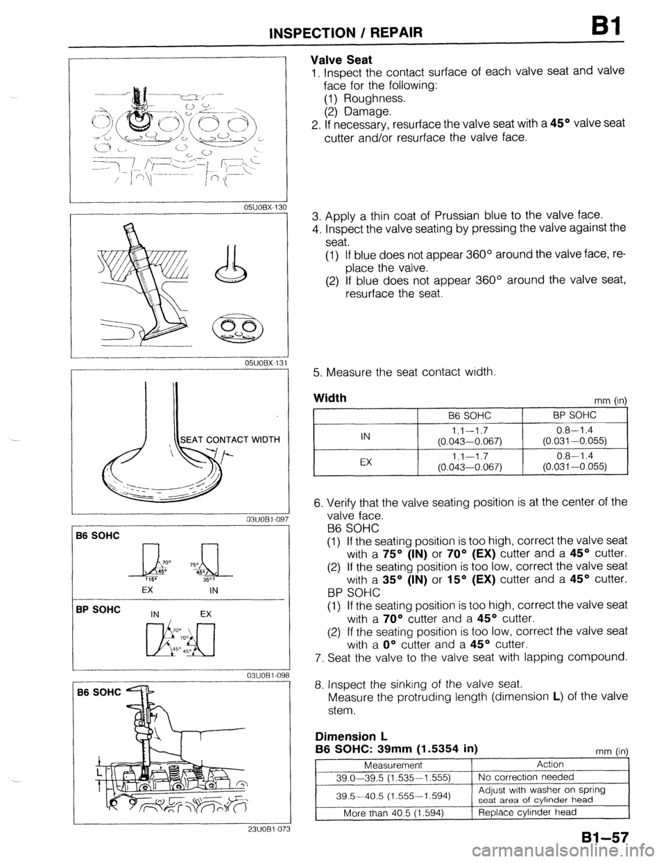
Valve Seat
1, Inspect the contact surface of each valve seat and valve
face for the following:
(1) Roughness.
(2) Damage.
2. If necessary, resurface the valve seat with a 45O valve seat
cutter and/or resurface the valve face.
3. Apply a thin coat of Prussian blue to the valve face.
4. Inspect the valve seating by pressing the valve against the
seat.
(1) If blue does not appear 360° around the valve face, re-
place the valve.
(2) If blue does not appear 360° around the valve seat,
resurface the seat
5. Measure the seat contact width.
Width
mm (in)
96 SOHC BP SOHC
IN l.l--1.7 0.8-l .4
(0.043-0.067) (0.031-0.055)
EX 1.1-1.7 0.8-l .4
(0.043-0.067) (0.031-0.055)
6. Verify that the valve seating position is at the center of the
valve face.
B6 SOHC
(1) If the seating position is too high, correct the valve seat
with a 75O (IN) or 70° (EX) cutter and a 45O cutter.
(2) If the seating position is too low, correct the valve seat
with a 35O (IN) or 15O (EX) cutter and a 45O cutter.
BP SOHC
(1) If the seating position is too high, correct the valve seat
with a 70° cutter and a 45O cutter.
(2) If the seating position is too low, correct the valve seat
with a O” cutter and a 45O cutter.
7. Seat the valve to the valve seat with lapping compound.
8. Inspect the sinking of the valve seat.
Measure the protruding length (dimension L) of the valve
stem.
Dimension L
B6 SOHC: 39mm
(1.5354 in) mm fin
Page 189 of 1164
INSPECTION / REPAIR 82
OWOBX-13
SEAT CONTACT WIDTH
I OWOBX-132
IN EX
700
Li!!b!J
700
45O 450
r
----
0311082 Oe
_---- _---
1
05UOBX-1:
Gi
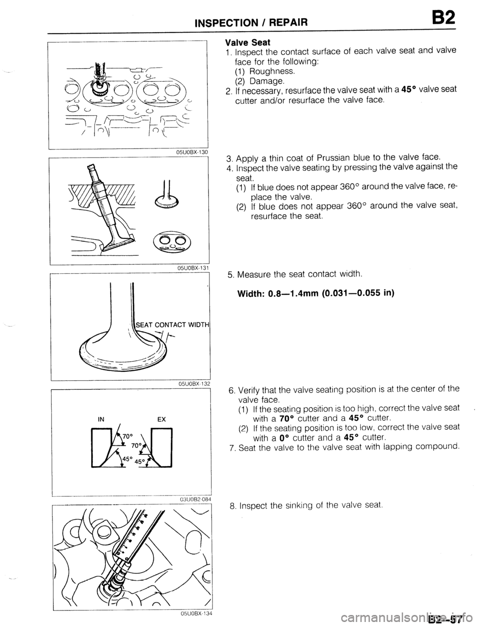
Valve Seat
1, Inspect the contact surface of each valve seat and valve
face for the following:
(1) Roughness.
(2) Damage.
2. If necessarv, resurface the valve seat with a 45’ valve seat
cutter and/br resurface the valve face.
3. Apply a thin coat of Prussian blue to the valve face.
4. Inspect the valve seating by pressing the valve against the
seat.
(1) If blue does not appear 360° around the valve face, re-
place the valve.
(2) If blue does not appear 360° around the valve seat,
resurface the seat.
5. Measure the seat contact width.
Width: 0.8-l .4mm (0.031-0.055 in)
6. Verify that the valve seating position is at the center of the
valve face.
(1) If the seating position is too high, correct the valve seat
with a 70° cutter and a 45O cutter.
(2) If the seating position is too low, correct the valve seat
with a O” cutter and a 45’ cutter.
7. Seat the valve to the valve seat with lapping compound.
8. Inspect the sinking of the valve seat.
B2-57
Page 296 of 1164
F TROUBLESHOOTING GUIDE
SYMPTOM TROUBLESHOOTING
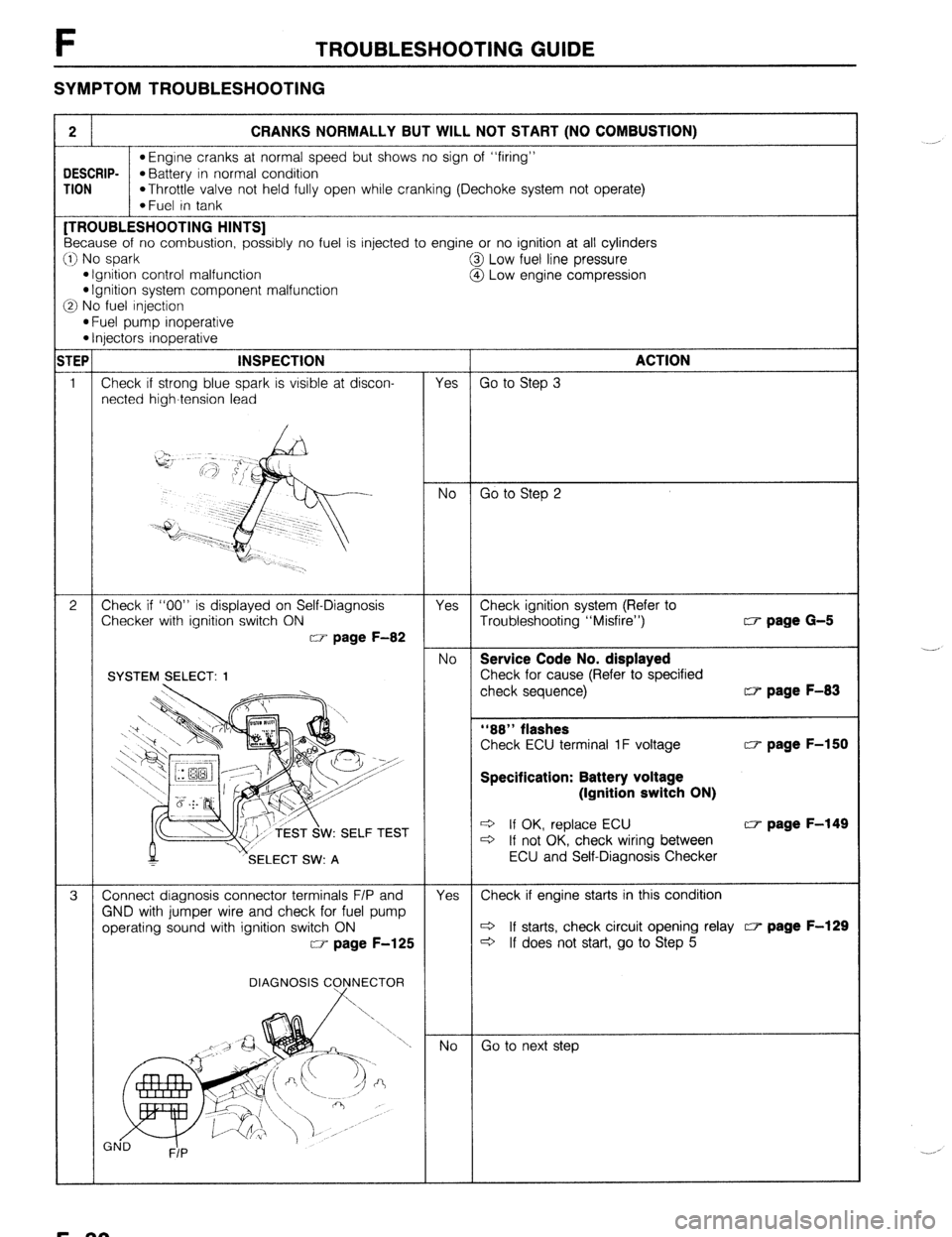
2 CRANKS NORMALLY BUT WILL NOT START (NO COMBUSTION)
l Engine cranks at normal speed but shows no sign of “firing”
DESCRIP-
*Battery in normal condition
TION
*Throttle valve not held fully open while cranking (Dechoke system not operate)
*Fuel in tank [TROUBLESHOOTING HINTS]
Because of no combustion, possibly no fuel is injected to engine or no ignition at all cylinders
:I) No spark
@I Low fuel line pressure
l Ignition control malfunction
@ Low engine compression l Ignition system component malfunction
3 No fuel injection
l Fuel pump inoperative l Injectors inoperative
TEP INSPECTION
ACTION
1 Check if strong blue spark is visible at discon-
Yes Go to Step 3
netted high-tension lead
No Go to Step 2
2 Check if “00” is displayed on Self-Diagnosis
Yes Check ignition system (Refer to
Checker with ignition switch ON
Troubleshooting “Misfire”) w page G-5
w page F-82
No Service Code No. displayed
Check for cause (Refer to specified
check sequence) w page F-83
“88” flashes
Check ECU terminal 1F voltage w page F-150
Specification: Battery voltage
(Ignition switch ON)
W: SELF TEST e If OK, replace ECU w page F-149 c3 If not OK, check wiring between
SELECT SW: A ECU and Self-Diagnosis Checker
3 Connect diagnosis connector terminals F/P and
Yes Check if engine starts in this condition
GND with jumper wire and check for fuel pump
operating sound with ignition switch ON c3 If starts, check circuit opening relay c7 page F-129
w page F-125
c3 If does not start, go to Step 5
DIAGNOSIS C
Go to next step ._-,
._. ,
F-30
Page 308 of 1164
![MAZDA 323 1989 Factory Repair Manual F TROUBLESHOOTING GUIDE
8 ROUGH IDLE/ENGINE STALLS AT IDLE - ALWAYS
bESCRIP- l Engine starts normally but stalls or vibrates excessively at idle in every condition
‘ION TROUBLESHOOTING HINTS]
D MAZDA 323 1989 Factory Repair Manual F TROUBLESHOOTING GUIDE
8 ROUGH IDLE/ENGINE STALLS AT IDLE - ALWAYS
bESCRIP- l Engine starts normally but stalls or vibrates excessively at idle in every condition
‘ION TROUBLESHOOTING HINTS]
D](/manual-img/28/57053/w960_57053-307.png)
F TROUBLESHOOTING GUIDE
8 ROUGH IDLE/ENGINE STALLS AT IDLE - ALWAYS
bESCRIP- l Engine starts normally but stalls or vibrates excessively at idle in every condition
‘ION TROUBLESHOOTING HINTS]
D Air/Fuel mixture too lean @ Incorrect idle speed
l Air leakage l Idle speed misadjustment l Fuel injection control malfunction l Idle speed control malfunction
*Low fuel line pressure @ One or more spark plugs not firing
3 One or more injectors clogged or not operating @ Low engine compression
3 Low intake air amount @ Airflow meter stuck INSPECTION
1
1
2
3
4
5
6
- Check if “00” is displayed on Self-Diagnosis
Checker with ignition switch ON w page F-82
SYSTEM2ELECT: 1
M v’SELECT SW: A TEST
Check if ECU terminal voltages are OK
MTX...Especially 2D, 20 and 2Q
ATX... Especially 2B, 2E and 3D CT page F-150
Disconnect high-tension lead at idle and check if
engine speed decreases equally at each cylinder
Check for injector operating sound at idle
Check if battery voltage exists at injector connec-
tor (W/R) wire
Check if strong blue spark is visible at discon-
nected high-tension lead
, Yes No Service Code No. displayed
Check for cause (Refer to specified
:heck sequence) “88” flashes
Check ECU terminal IF voltage CT page F-150
Specification: Battery voltage
(Ignition switch ON)
3 If OK, replace ECU w page F-149 3 If not OK, check wiring between
ECU and Self-Diaanosis Checker Yes
Go to next step No
Check for cause Yes
Go to Step 8 No
Go to next step
Go to Step 6
Go to Step 5 Yes
No
Yes
No
Yes
No I-
30 to next step w page F-83
0 page F-151
Check if injector resistance is OK c7 page F-131
Resistance: Approx. 12-l 852
c3 If OK, check wiring between ECU
and injector
c3 If not OK, replace injector w page F-131
Check wiring between ECU and injector
Go to next step
Check high-tension lead w page G-17
Q If OK, check distributor cap and
rotor w page G-22
c3 If not OK, replace high-tension lead
F-42
Page 319 of 1164

TROUBLESHOOTING GUIDE F
No Replace airflow meter
9
Check for injector operating sound at idle Yes Go to Step 11
No Go to next Step
10 Check if battery voltage exists at injector connec- Yes Check if injector resistance is OK CT page F-131
tor (W/R) wire Resistance: 12-l 6fi
c3 If OK, check wiring between ECU
and injector
c3 If not OK, replace injector CT page F-131
No
Check wiring between ECU and injector
11 Check if strong blue spark is visible at discon-
Yes Go to next step
netted high-tension lead
No Check high-tension lead
+ If OK, check distributor cap and
rotor w page G-22
* If not OK, replace high-tension lead
12
Check if spark plugs are OK Yes Check for correct engine compression CT page Bl-10
w page G-16 82-10
Compression (Minimum):
. BP SOHC
834 kPa (8.5 kg/cm2, 121 psi)300 rpm
BON BUILDUP l BP DOHC
883 kPa (9.0 kg/cm*, 128 psi)-300 rpm
l.O-l.lmm ’ B6 DAMAGE AND 932 kPa (9.5 kg/cm’, 135 psi)-300 rpm DETERIORATION
c3 If OK, go to next step
c13 If not OK, check for cause CT page Bl-10
B2-10
No
Clean or replace w page G-18
13
Check for injector leakage Yes Replace injector CT page F-131
w page F-132
No Go
to next step
14 Try known good ECU and check if condition im-
proves cc7 page F-149
23UOFX-030
F-53
Page 445 of 1164
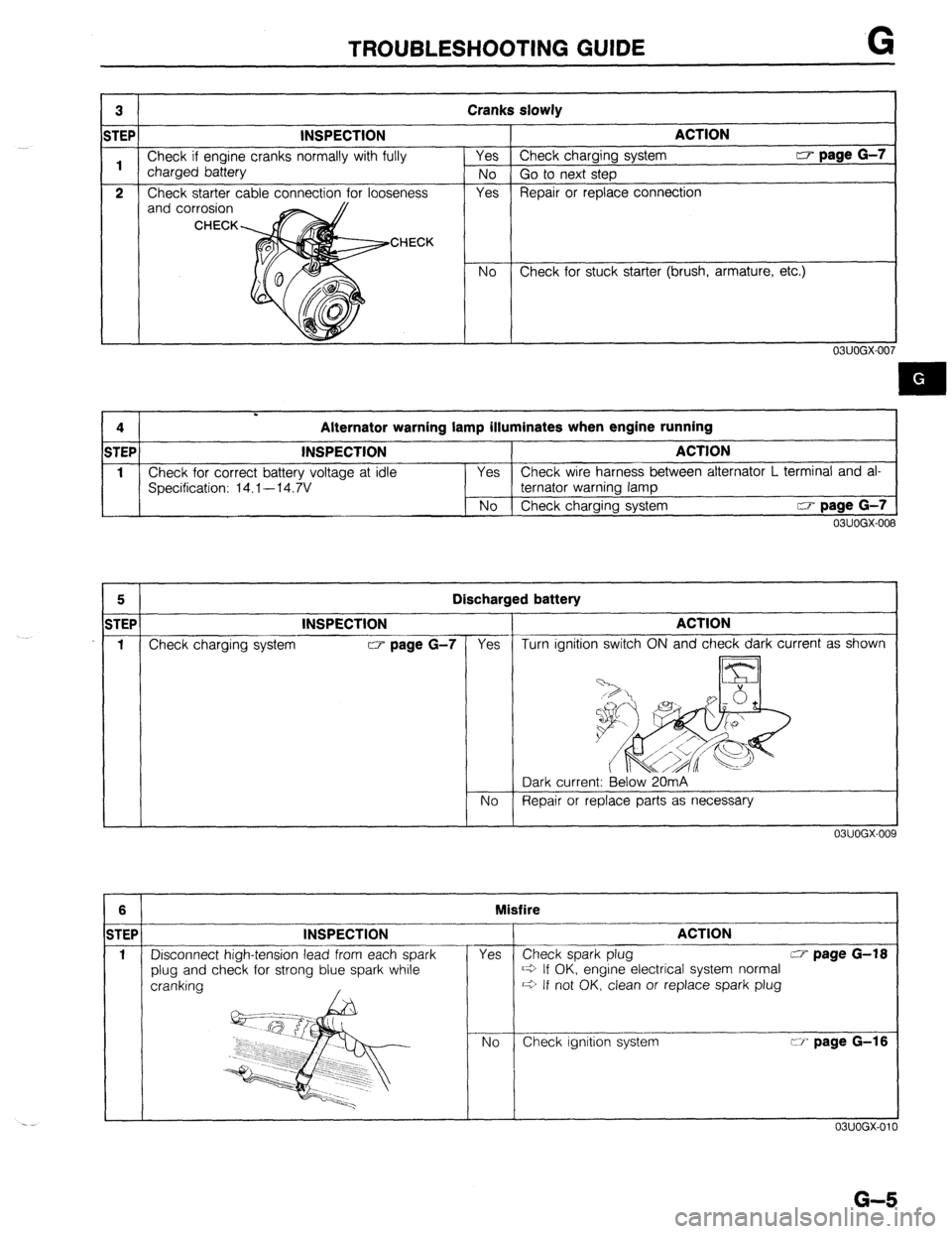
TROUBLESHOOTING GUIDE G
3 Cranks slowly
STEP INSPECTION ACTION
1 Check if engine cranks normally with fully Yes Check charging system CT page G-7
charged battery
No Go to next step
2 Check starter cable connection for looseness Yes Repair or replace connection
and corrosion
OBUOGX-OC
I 1 4
.
Alternator warning lamp illuminates when engine running
STEP INSPECTION ACTION
1 Check for correct battery voltage at idle Yes Check wire harness between alternator L terminal and aI*
Specification: 14.1--14.7V ternator warning lamp
No Check charging system w page G-7
03UOGX-008
5 I Discharged battery I 1TEP INSPECTION
f Check charging system w page G-7 -
6
TEF
1
r
--
Yes
03UOGX-009
ACTION
Turn ignition switch ON and check dark current as shown
Dark current: Below 20mA
No Repair or replace parts as necessary 1
Misfire
INSPECTION
-
Disconnect high-tension lead from each spark
plug and check for strong blue spark while
cranking
, i
Yes
No T-
I
ACTION
- Check spark plug w page G-f8
~3 If OK, engine electrical system normal
~3 If not OK, clean or replace spark plug
Check ignition system ci’ page G-16
1 03UOGX-010
G-5