1989 MAZDA 323 interior
[x] Cancel search: interiorPage 907 of 1164
INTERIOR LAMP SYSTEM T
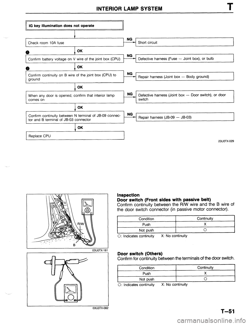
IG key illumination does not operate
Check room IOA fuse NG
- Short circuit
0 OK
Confirm battery voltage on V Defective harness (Fuse - Joint box), or bulb
0 OK
Confirm continuity on B wire of the joint box (CPU) to
ground Repair harness (Joint box - Body ground)
OK
When any door is opened, confirm that interior lamp
comes on
OK NG
~ Defective harness (Joint box - Door switch), or door
switch
Confirm continuity between N terminal of JB-09 connec- _ NG
-
tor and B terminal of JB-03 connector Repair harness (JB-09 - JB-03)
I OK
Replace CPU
23UOTX-029
Inspection
Door switch (Front sides with passive belt)
Confirm continuity between the R/W wire and the B wire of
the door switch connector (in passive motor connector).
Condition Continuity
Push X
Not push 0
0: Indicates continuity X: No continuity
03UOTX-181 Door switch (Others)
Confirm for continuity between the terminals of the door switch.
Condition Continuity
Push X
Not push 0
0: Indicates continuity X: No continuity
1 I OSJOTX-082
T-51
Page 908 of 1164
.T INTERIOR LAMP SYSTEM
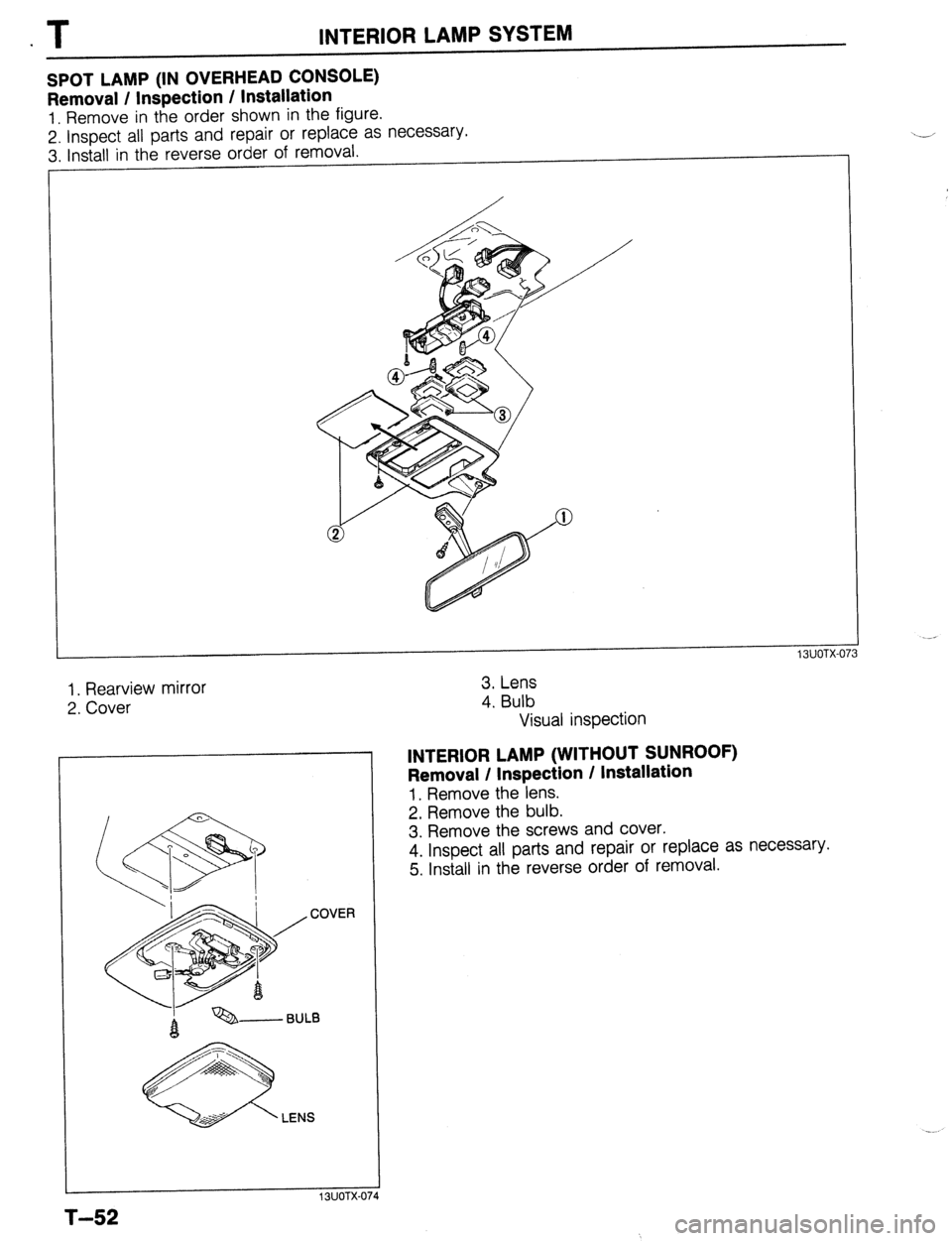
SPOT LAMP (IN OVERHEAD CONSOLE)
Removal / Inspection / Installation
1. Remove in the order shown in the figure.
2. lnsoect all parts and repair or replace as necessary.
3. Install in the reverse order of removal.
1. Rearview mirror
2. Cover
LENS
3. Lens
4. Bulb
Visual inspection
INTERIOR LAMP (WITHOUT SUNROOF)
Removal / Inspection / Installation
1. Remove the lens.
2. Remove the bulb.
3. Remove the screws and cover.
4. Inspect all parts and repair or replace as necessary.
5. Install in the reverse order of removal.
T-52
Page 909 of 1164
INTERIOR LAMP SYSTEM T
COVER
LENS
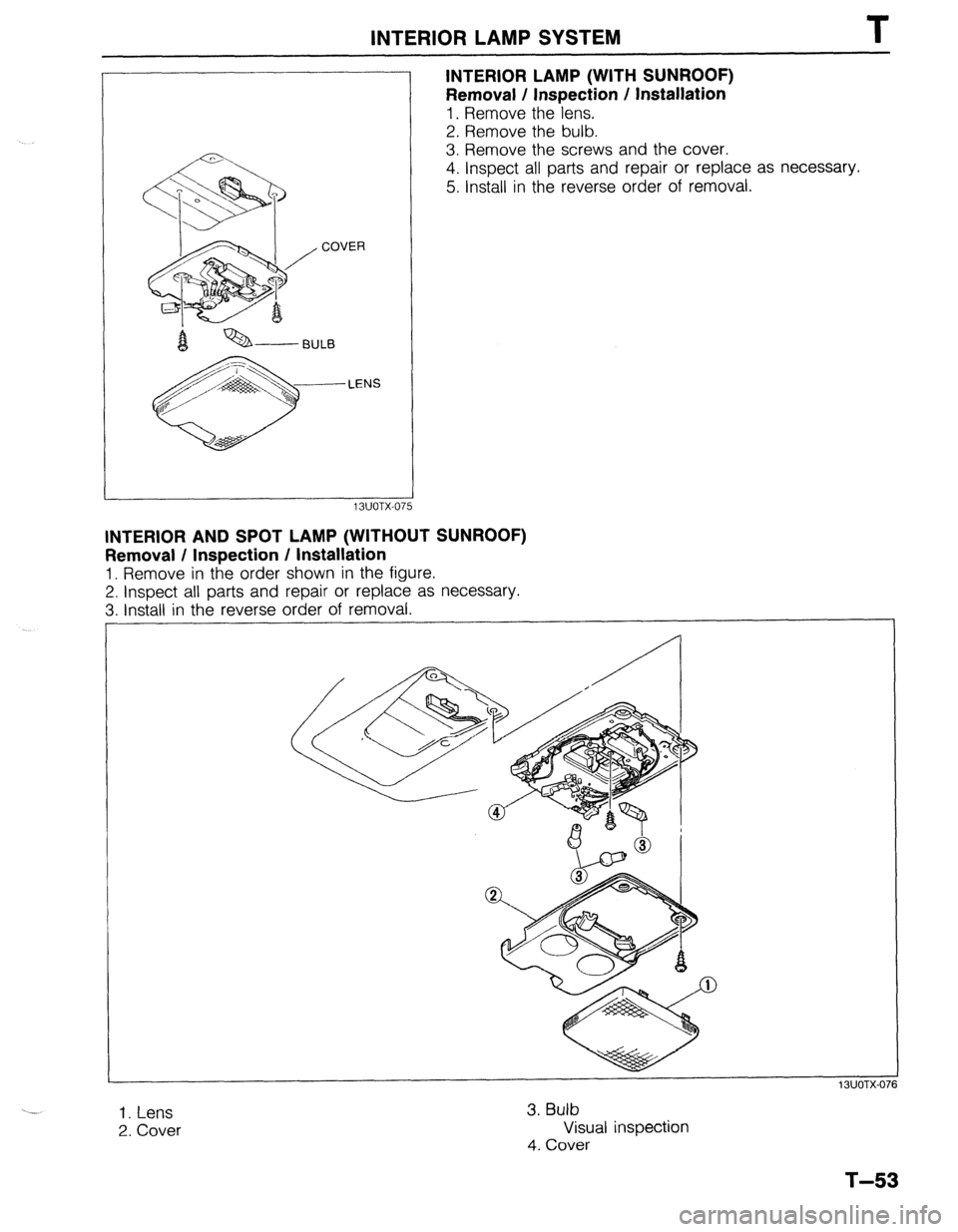
INTERIOR LAMP (WITH SUNROOF)
Removal / Inspection / Installation
1. Remove the lens.
2. Remove the bulb.
3. Remove the screws and the cover.
4. Inspect all parts and repair or replace as necessary.
5. Install in the reverse order of removal.
ILIVYCA-VI 5
INTERIOR AND SPOT LAMP (WITHOUT SUNROOF)
Removal / Inspection / Installation
1. Remove in the order shown in the figure.
2. Inspect all parts and repair or replace as necessary.
3. Install in the reverse order of removal.
‘- 1. Lens
2. Cover 3. Bulb
Visual inspection
4. Cover
T-53
Page 910 of 1164
T INTERIOR LAMP SYSTEM
13UOTX-077 d-------BULB
LENS
T-54
13UOTX-07
23UOTX-0
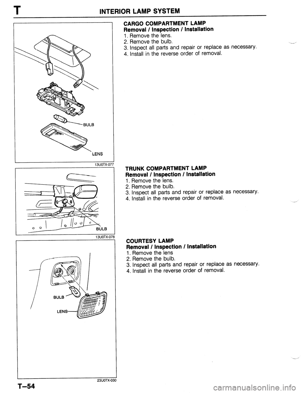
CARGO COMPARTMENT LAMP
Removal / Inspection / Installation
1. Remove the lens.
2. Remove the bulb.
3. Inspect all parts and repair or replace as necessary.
4. Install in the reverse order of removal.
TRUNK COMPARTMENT LAMP
Removal / Inspection / Installation
1. Remove the lens.
2. Remove the bulb.
3. Inspect all parts and repair or replace as necessary.
4. Install in the reverse order of removal.
COURTESY LAMP
Removal / Inspection / Installation
1. Remove the lens
2. Remove the bulb.
3. Inspect all parts and repair or replace as necessary.
4. Install in the reverse order of removal.
Page 1034 of 1164
TD TECHNICAL DATA
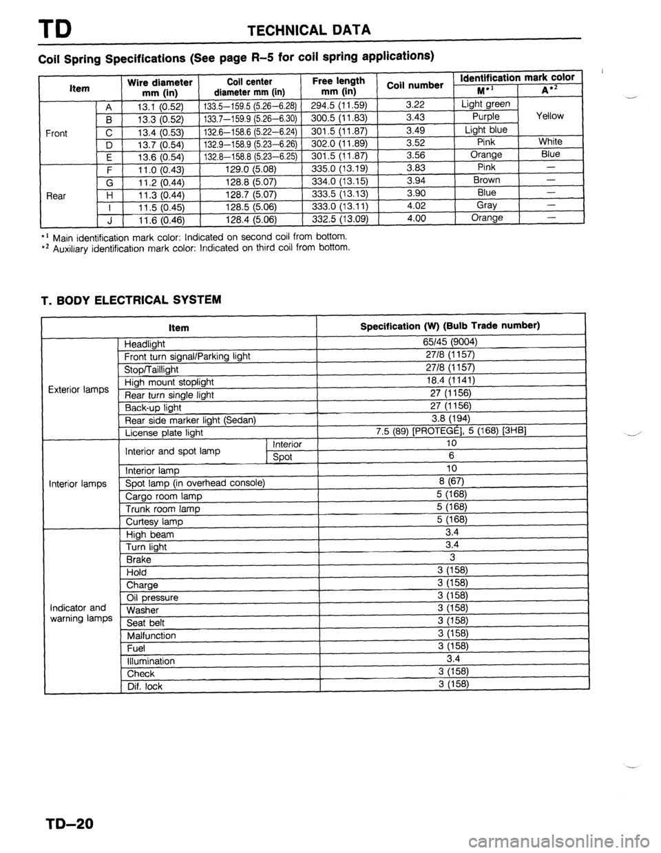
Coil Spring Specifications (See page R-5 for coil spring applications)
*’ Main identification mark color: Indicated on second coil from bottom. l * Auxiliary identification mark color: Indicated on third coil from bottom.
T. BODY ELECTRICAL SYSTEM
Item
Headlight
Frnnt tl wn sinnnl/Pnrkinn linht
Specification (W) (Bulb Trade number)
65145 (9004)
2718 II I 571
I
“‘VW, I u”“y’ 1. I” \’ ‘V’,
uinh mount stoplight 18.4 (1141)
turn single light 27 (1156)
Y-,-~p light 27 (1156)
Rear side marker light (Sedan) 3.8 (194)
License plate light 7.5 (89) [PROTEGE], 5 (168) [3HBl
Interior 10
Interior and spot lamp
spot 6
Interior lamp 10
‘i--” Spot lamp (in overhead console)
8 (67)
Cargo room lamp 5 (168)
Trunk room lamp 5 (168)
I I
ntminr Iamnc
I
Curtesy lamp
High beam
Turn light
Brake
Hold
) Charge 5 (168)
3.4
3.4
3
3 (158)
i
Oil pressure
Washer
Seat belt
Malfunction
Fuel
illumination 3 (158)
3 (158)
3 (158)
3 (158)
3 (158)
3 (158)
3.4 Indicator and
warning lamps
Check 3 (158)
Dif. lock
I 3 (158) .-
,
-.-’
I
I
TD-20
Page 1050 of 1164
PARTS INDEX
I
CRANKSHAFT.. ....................................
I31 -64
CYLINDER BLOCK .............................. 61-60
CYLINDER HEAD..
............................... 81-54
CYLINDER HEAD GASKET .................
Bl-16
DRIVE BELT(S). ...................................... 81-5
FRONT OIL SEAL ................................ 81-23
HLA .............................................. Bl-7,20,60
OIL JET ................................................ 81-61
PISTON.. ...............................................
Bl-62
PISTON PIN..
........................................ 81-62
PISTON RING
....................................... 81-62
REAR
OIL SEAL..
................................. 81-25
TENSIONER, IDLER ............................. Bl-65
TENSIONER
SPRING ...........................
Bl-65
TIMING BELT ..................................
Bl-12,65
TIMING BELT PULLEY ........................
Bl-65
VALVE MECHANISM ........................... Bl-55
ENGINE
(BP DOHC) .................................... B2-2
CAMSHAFT ..........................................
82-58
CAMSHAFT PULLEY ...........................
B2-65
CONNECTING ROD..
........................... 82-63
CRANKSHAFT ......................................
B2-64
CYLINDER BLOCK ..............................
82-60
CYLINDER
HEAD.. ............................... B2-54
CYLINDER HEAD GASKET .................
82-16
DRIVE
BELTS.. .......................................
B2-5
FRONT
OIL SEAL ................................
82-26
H LA ..............................................
OIL JET .......................... B2-7iyL;;
......................
PISTON .................................................
B2-62
PISTON PIN ..........................................
82-62
PISTON RING..
..................................... 82-62
REAR OIL SEAL ................................... B2-28
TENSIONER, IDLER ............................. B2-65
TENSIONER SPRING ........................... B2-65
TIMING
BELT.. ................................
B2-12,65
TIMING BELT PULLEY ........................ 82-65
VALVE MECHANISM ........................... 82-55
ENGINE CONTROL UNIT (ECU) ............... F-149
ENGINE COOLANT
........................................ E-5
ENGINE OIL.. .................................................
D-7
ENGINE OIL FILTER.. .................................... D-8
’ EXHAUST SYSTEM. ...................................
F-136
EXTRACTOR CHAMBER .............................. S-53
F
FAN MOTOR (COOLING FAN). ................... E-14
FAN RELAY (COOLING FAN). ..................... E-18
FLASHER UNIT ............................................
T-17
FLOORMAT ..................................................
S-99
FLYWHEEL ..................................................
H-18
FRONT AXLE .................................................
M-4
FRONT BRAKE ............................................
P-l 8
FRONT BUMPER ......................................... S-39
FRONT DOOR ................................................
S-8
FRONT DOOR LOCK AND OPENER ..........
S-13
PI-2
FRONT FENDER PANEL ............................... S-7
FRONT LOWER ARM .................................. R-16
FRONT SHOCK ABSORBER AND SPRING R-11
FRONT SIDE WINDOW REGULATOR AND
GLASS ........................................................ S-10
FRONT STABILIZER..
................................... R-l 8
FRONT SUSPENSION .................................. R-l 0
FUEL FILLER LID AND OPENER..
.............. S-37
FUEL FILTER .............................................. F-l 24
FUEL GAUGE SENDER UNIT ..................... T-73
FUEL PUMP ............................................... F-125
FUEL TANK
................................................ F-123
FUSE AND JOINT BOX.. .............................. T-12
H
HEADLIGHT AND
FRONT COMBINATION LIGHT..
................ T-41
HEADLIGHT RELAY ..................................... T-l 8
HEADLINER ................................................. S-89
HEATER CONTROL UNIT.. ......................... U-26
HEATER UNIT
.............................................. U-21
HIGH-MOUNT STOPLIGHT
.......................... T-45
HIGH-TENSION LEAD ................................. G-l 7
HOOD ............................................................. S-5
HORN T-88
...........................................................
HORN RELAY
.......................................... T-18,88
.__. ’
I I
IGNITER .......................................................
G-23
IGNITION COIL.. .......................................... G-19
INJECTOR .................................................. F-l 31
INSTRUMENT CLUSTER
AND SPEEDOMETER CABLE
.................... T-69
INTAKE MANIFOLD ................................... F-113
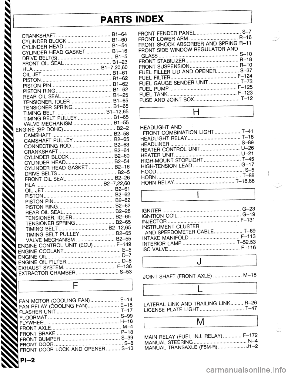
INTERIOR LAMP ..................................... T-52,53
ISC VALVE.. ................................................ F-l 16
J
JOINT SHAFT (FRONT AXLE) .................... M-18
L
LATERAL LINK AND TRAILING LINK.. ....... R-26
LICENSE PLATE LIGHT.. ............................. T-47
i
M
I
---
MAIN RELAY (FUEL INJ. RELAY). ............ F-172
MANUAL STEERING ..................................... N-4
MANUAL TRANSAXLE (F5M-R). .................. Jl-2
Page 1055 of 1164
Z
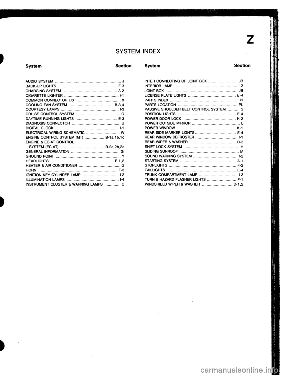
SYSTEM INDEX
System Section System Section
AUDIO SYSTEM ......................................................... J
BACK-UP LIGHTS ...................................................
F-3
CHARGING SYSTEM ............................................... A-2
CIGARETTE LIGHTER ............................................... I-1
COMMON CONNECTOR LIST ..................................... X
COOLING FAN SYSTEM ....................................... B-3.4
COURTESY LAMPS .................................................. l-3
CRUISE CONTROL SYSTEM ...................................... Q
DAYTIME RUNNING UGHTS .................................... E-3
DIAGNOSIS CONNECTOR .......................................... U
DIGITAL CLOCK ....................................................... l-l
ELECTRICAL WIRING SCHEMATIC ............................. W
ENGINE CONTROL SYSTEM (MT) ................. B-l a, 1 b, 1 c
ENGINE 8 EC-AT CONTROL
SYSTEM (EC-AT) ...................................... B-2a,2b,2c
GENERAL INFORMATION .......................................... GI
GROUND POINT ........................................................ Y
HEADLIGHTS ....................................................... E-l ,2
HEATER 8 AIR CONDITIONER .................................... G
HORN .................................................................... F-3
IGNITION KEY CYLINDER LAMP ............................... l-2
ILLUMINATION LAMPS .............................................
l-4
INSTRUMENT CLUSTER . WARNING LAMPS .............. C INTER CONNECTING OF JOINT BOX ......................... JB
INTERIOR LAMP ...................................................... l-2
JOINT BOX .............................................................. JB
LICENSE PLATE UGHTS ......................................... E-4
PARTS INDEX ........................................................... PI
PARTS LOCATION ................................................... PL
PASSIVE SHOULDER BELT CONTROL SYSTEM .......... S
POSITION LIGHTS ................................................... E-4
POWER DOOR LOCK ............................................. K-2
POWER OUTSIDE MIRROR ......................................... L
POWER WINDOW ................................................... K-l
REAR SIDE MARKER LIGHTS.. ................................. E-4
REAR WINDOW DEFROSTER .................................... I-1
REAR WIPER 8 WASHER ........................................ D-3
SHIFT-LOCK SYSTEM ................................................ H
SLIDING SUNROOF ................................................... M
SOUND WARNING SYSTEM ...................................... l-2
STARTING SYSTEM ................................................ A-l
STOPLIGHTS .......................................................... F-2
TAILLIGHTS ............................................................ E-4
TRUNK COMPARTMENT LAMP ................................. l-3
TURN 8 HAZARD FLASHER UGHTS ......................... F-l
WINDSHIELD WIPER 8 WASHER .......................... D-l ,2
Page 1059 of 1164
I
E
,
1
I
i
t
1
I
!
!
I
t:
I.
1.
i
i
Reading Wiring Diagrams Z-Gl-3
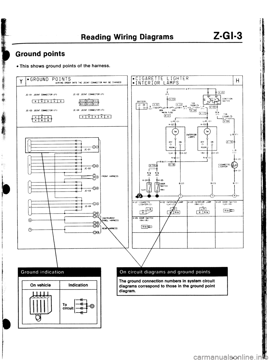
Ground points
l This shows ground points of the harness.
CIGARETTE LIGHTER
INTERIOR LAMPS
H
I On vehicle
I Indication
I
To circuit The ground connection numbers in system circuit
diagrams correspond to those in the ground point
diagram.