1989 MAZDA 323 cooling system
[x] Cancel search: cooling systemPage 429 of 1164
CONTROL SYSTEM F
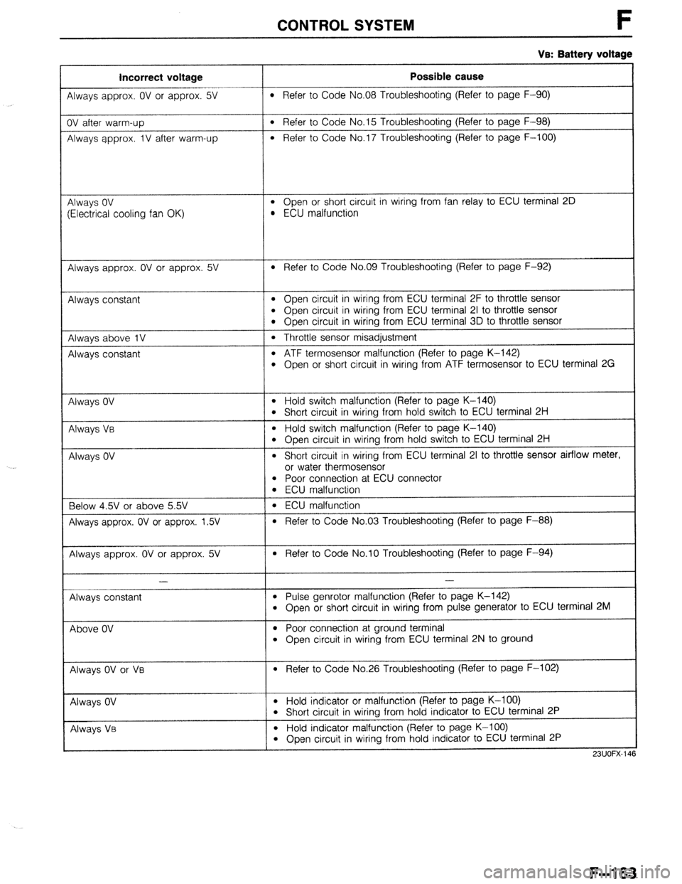
Incorrect voltage Possible cause ____-__l_ll____-
Always approx. OV or approx. 5V l Refer to Code No.08 Troubleshooting (Refer to page F-90)
IV after warm-up
Jlways approx. IV after warm-up
l Refer to Code No.15 Troubleshooting (Refer to page F-98)
l Refer to Code No.1 7 Troubleshooting (Refer to page F-100)
qlways OV
Electrical cooling fan OK)
l Open or short circuit in wiring from fan relay to ECU terminal 20 l ECU malfunction
I Always approx. OV or approx. 5V l Refer to Code No.09 Troubleshooting (Refer to page F-92)
Always constant
C\lways above 1V
4lways constant . Open circuit in wiring from ECU terminal 2F to throttle sensor
l Open circuit in wiring from ECU terminal 21 to throttle sensor l Open circuit in wiring from ECU terminal 3D to throttle sensor
l Throttle sensor misadjustment
l ATF termosensor malfunction (Refer to page K-142) l Open or short circuit in wiring from ATF termosensor to ECU terminal 2G
c\lways OV
l Hold switch malfunction (Refer to page K-140) l Short circuit in wiring from hold switch to ECU terminal 2H
4lways Va
l Hold switch malfunction (Refer to page K-140) l Open circuit in wiring from hold switch to ECU terminal 2H
Always OV
l Short circuit in wiring from ECU terminal 21 to throttle sensor airflow meter,
or water thermosensor
l Poor connection at ECU connector
Below 4.W or above 5.W
Always approx. OV or approx. I..% l ECU malfunction
l ECU malfunction
l Refer to Code No.03 Troubleshooting (Refer to page F-88)
Always approx. OV or approx. 5V 9 Refer to Code No.10 Troubleshooting (Refer to page F-94)
I
- - VB:
Battery voltage
Always constant
l Pulse genrotor malfunction (Refer to page K-142) l Open or short circuit in wiring from pulse generator to ECU terminal 2M
Above OV
l Poor connection at ground terminal l Open circuit in wiring from ECU terminal 2N to ground
F-l 63
Page 869 of 1164
FUSE AND JOINT BOX
FUSES
Specifications
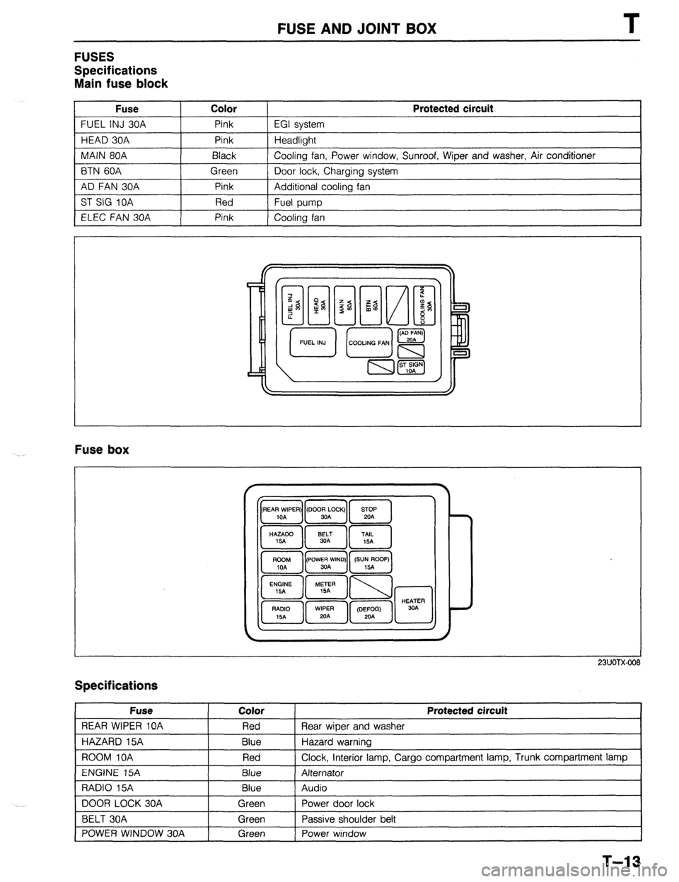
Main fuse block
Fuse Color
FUEL INJ 30A Pink
HEAD 30A Pink
MAIN 80A Black
BTN 60A Green
AD FAN 30A Pink
ST SIG 10A Red
ELEC FAN 30A Pink Protected circuit
EGI system
Headlight
Cooling fan, Power window, Sunroof, Wiper and washer, Air conditioner
Door lock, Charging system
Additional cooling fan
Fuel pump
Cooling fan
Fuse box
23UOTX-001
Specifications
Fuse
REAR WIPER 10A
HAZARD 15A
ROOM IOA
ENGINE 15A
RADIO 15A
DOOR LOCK 30A
BELT 30A
POWER WINDOW 30A Color
Red
Blue
Red
Blue
Blue
Green
Green
Green Protected circuit
Rear wiper and washer
Hazard warning
Clock, interior lamp, Cargo compartment lamp, Trunk compartment lamp
Alternator
Audio
Power door lock
Passive shoulder belt
Power window
1
T-13
Page 957 of 1164
U
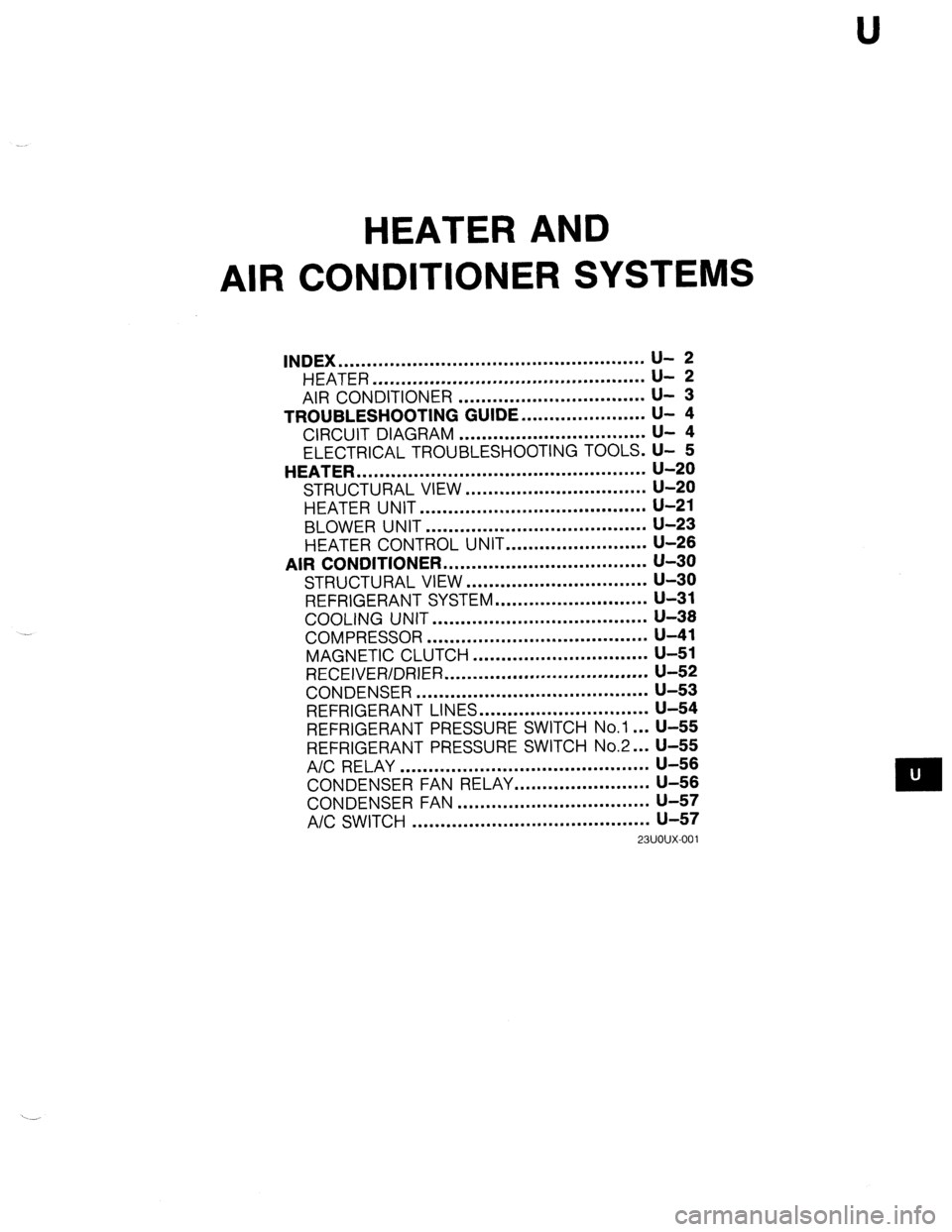
HEATER AND
AIR CONDITIONER SYSTEMS
INDEX ...................................................... u- 2
HEATER ................................................
AIR CONDITIONER ................................. ;r ;
TROUBLESHOOTING GUIDE.. .................... U- 4
CIRCUIT DIAGRAM ................................. u- 4
ELECTRICAL TROUBLESHOOTING TOOLS. U- 5
HEATER ................................................... u-20
STRUCTURAL VIEW ................................ u-20
HEATER UNIT ........................................ u-21
BLOWER UNIT ....................................... U-23
HEATER CONTROL UNIT.. ....................... U-26
AIR CONDITIONER .................................... u-30
STRUCTURAL VIEW ................................ u-30
REFRIGERANT SYSTEM ........................... u-31
COOLING UNIT ...................................... U-38
COMPRESSOR ....................................... u-41
MAGNETIC CLUTCH ............................... u-51
RECEIVER/DRIER .................................... U-52
CONDENSER ......................................... u-53
REFRIGERANT LINES .............................. u-54
REFRIGERANT PRESSURE SWITCH No.1.. . U-55
REFRIGERANT PRESSURE SWITCH No.2.. . U-55
A/C RELAY ............................................ U-56
CONDENSER FAN RELAY.. ......................
CONDENSER FAN .................................. z-f;
-
A/C SWITCH .......................................... u-57
23UOUX-001
Page 970 of 1164
TROUBLESHOOTING GUIDE
I I
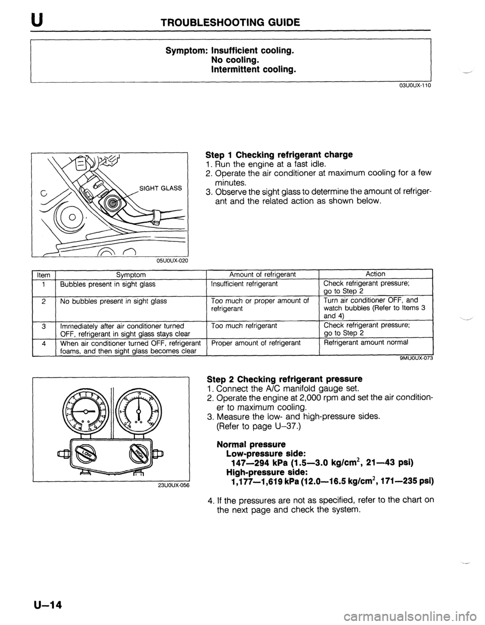
Symptom: Insufficient cooling.
No cooling.
Intermittent cooling.
I I
03uoux-110
SIGHT GLASS
o5uoux-020
Step 1 Checking refrigerant charge
1. Run the engine at a fast idle.
2. Operate the air conditioner at maximum cooling for a few
minutes.
3. Observe the sight glass to determine the amount of refriger-
ant and the related action as shown below.
Item Symptom Amount of refrigerant Action
1 Bubbles present in sight glass Insufficient refrigerant Check refrigerant pressure;
go to Step 2
2 No bubbles present in sight glass Too much or proper amount of Turn air conditioner OFF, and
refrigerant watch bubbles (Refer to Items 3
and 4)
__
3 Immediately after air conditioner turned Too much refrigerant Check refrigerant pressure;
OFF, refrigerant in sight glass stays clear go to Step 2
4 When air conditioner turned OFF, refrigerant
Proper amount of refrigerant Refrigerant amount normal
foams, and then sight glass becomes clear
9MUOUX-073
23UOUX-05i
Step 2 Checking refrigerant pressure
1. Connect the A/C manifold gauge set.
2. Operate the engine at 2,000 rpm and set the air condition-
er to maximum cooling.
3. Measure the low- and high-pressure sides.
(Refer to page U-37.)
Normal pressure
Low-pressure side:
147-294 kPa (1 J-3.0 kg/cm*, 21-43 psi)
High-pressure side:
1,177-1,619 kPa (12.0-16.5 kg/cm2, 171-235 psi)
4. If the pressures are not as specified, refer to the chart on
the next page and check the system.
u-14
Page 971 of 1164
TROUBLESHOOTING GUIDE U
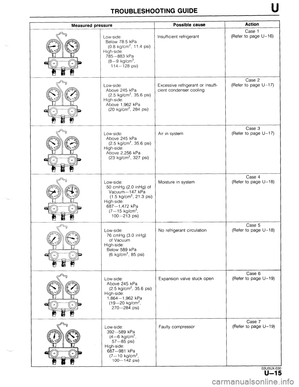
Measured press iure
_ow-side:
Below 78.5 kPa
(0.8 kg/cm’, 11.4 psi)
irgh-srde:
785 --883 kPa
(8-9 kg/cm’,
114-128 PSI)
-ow-srde:
Above 245 kPa
(2.5 kg/cm*, 35.6 psi)
iigh-srde:
Above 1,962 kPa
(20 kg/cm*, 284 PSI)
-ow-side:
Above 245 kPa
(2.5 kg/cm*, 35.6 PSI)
High-side:
Above 2,256 kPa
(23 kg/cm’, 327 psi)
Low-ade:
50 cmHg (2.0 inHg) of
Vacuum-l 47 kPa
(1.5 kg/cm2, 21.3 psi)
High-side:
687-i ,472 kPa
(7-15 kg/cm*,
loo-213 psi)
Low-side:
76 cmHg (3.0 inHg)
of Vacuum
High-side:
Below 589 kPa
(6 kg/cm’, 85 psi)
Low-side:
Above 245 kPa
(2.5 kg/cm’, 35.6 psi)
High-side:
1,864-l ,962 kPa
(19-20 kg/cm2,
270-284 psi)
-.
Low-side:
392-589 kPa
(4-6 kg/cm’,
57-85 psi)
High-side:
687-981 kPa
(7-10 kg/cm*,
100-I 42 psi)
T-
- Possible cause
nsufflcient refrigerant
!xcessive refrigerant or insuffi-
:ient condenser cooling
Air in system
Moisture in system
No refrigerant circulation
Expansion valve stuck open
Faulty compressor Action
Case 1
(Refer to page U-16)
Case 2
(Refer to page U-17)
Case 3
(Refer to page U-17)
Case 4
(Refer to page U-18)
Case 5
(Refer to page U-18)
Case 6
(Refer to page U-19)
Case 7
(Refer to page U-19)
03uoux-0:
u-1
Page 972 of 1164
U TROUBLESHOOTING GUIDE
Case 1: Insufficient refrigerant
Measured pressure
Low-pressure side: Less than 78.5 kPa (0.8 kg/cm2, 11.4 psi)
High-pressure side: 785-883 kPa (8-9 kg/cm2, 114-128 psi)
Condition
l Outlet air from vents not cold.
l Bubbles seen in sight glass.
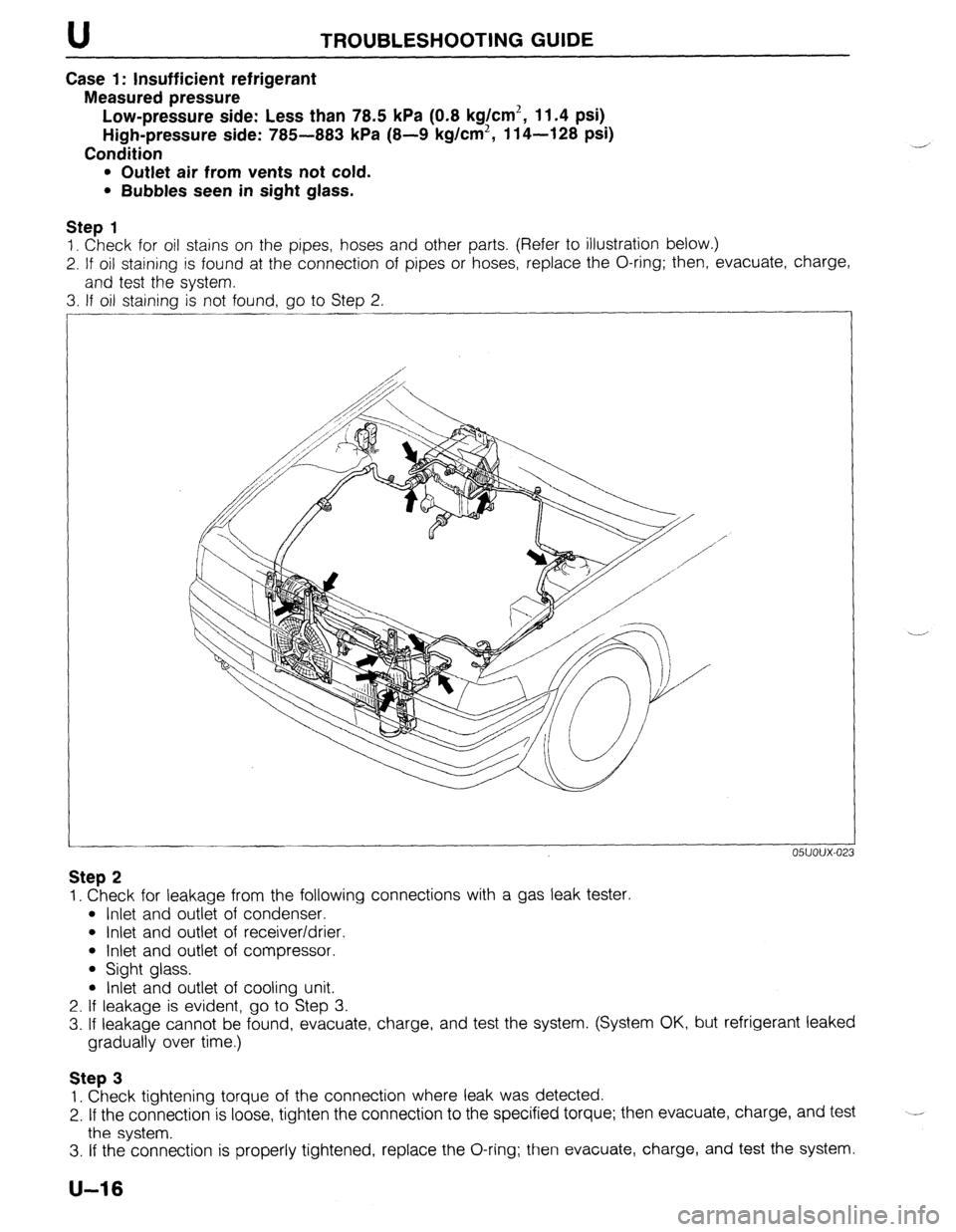
Step 1
1. Check for oil stains on the pipes, hoses and other parts, (Refer to illustration below.)
2. If oil staining is found at the connection of pipes or hoses, replace the O-ring; then, evacuate, charge,
and test the system.
3. If oil staining is not found, go to Step 2.
05UOUX-02
Step 2
1. Check for leakage from the following connections with a gas leak tester.
l Inlet and outlet of condenser.
l Inlet and outlet of receiver/drier.
l Inlet and outlet of compressor.
l Sight glass.
l Inlet and outlet of cooling unit.
2. If leakage is evident, go to Step 3.
3. If leakage cannot be found, evacuate, charge, and test the system. (System OK, but refrigerant leaked
gradually over time.)
Step 3
1. Check tightening torque of the connection where leak was detected.
2. If the connection is loose, tighten the connection to the specified torque; then evacuate, charge, and test
the system. --
3. If the connection is properly tightened, replace the O-ring; then evacuate, charge, and test the system.
U-16
Page 973 of 1164
TROUBLESHOOTING GUIDE U
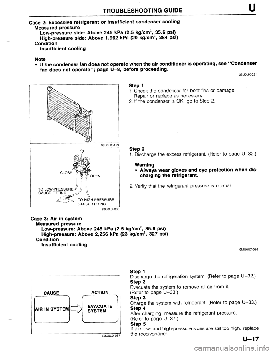
Case 2: Excessive refrigerant or insufficient condenser cooling
Measured pressure
Low-pressure side: Above 245 kPa (2.5 kg/cm2, 35.6 psi)
High-pressure side: Above 1,962 kPa (20 kg/cm2, 284 psi)
Condition
Insufficient cooling
Note
l If the condenser fan does not operate when the air conditioner is operating, see “Condenser
fan does not operate”; page U-8, before proceeding.
TO LOW
GAUGE
H-PRESSURE
GAUGE FITTING
13uoux-00 5 03uoux-031
Step 1
1. Check the condenser for bent fins or damage.
Repair or replace as necessary.
2. If the condenser is OK, go to Step 2.
Step 2
1. Discharge the excess refrigerant. (Refer to page U-32.)
Warning
l Always wear gloves and eye protection when dis-
charging the refrigerant.
2. Verify that the refrigerant pressure is normal.
Case 3: Air in system
Measured pressure
Low-pressure: Above 245 kPa (2.5 kg/cm2, 35.6 psi)
High-pressure: Above 2,256 kPa (23 kg/cm2, 327 psi)
Condition
Insufficient cooling
. . CAUSE ACTION
AIR IN SYSTEM EVACUATE
SYSTEM
9MUOUX-086
Step 1
Discharge the refrigeration system. (Refer to page U-32.)
Step 2
Evacuate the system to remove all air from it.
gFI;;r; page U-33.)
Charge the system with refrigerant. (Refer to page U-33.)
Step 4
After charging, measure the refrigerant pressure.
(Refer to page U-37.)
Step 5
If the low- and high-pressure sides are still too high, replace
I
23UOUX-057 the receiver/drier.
Page 974 of 1164
U TROU6LESHOOTlNG GUIDE
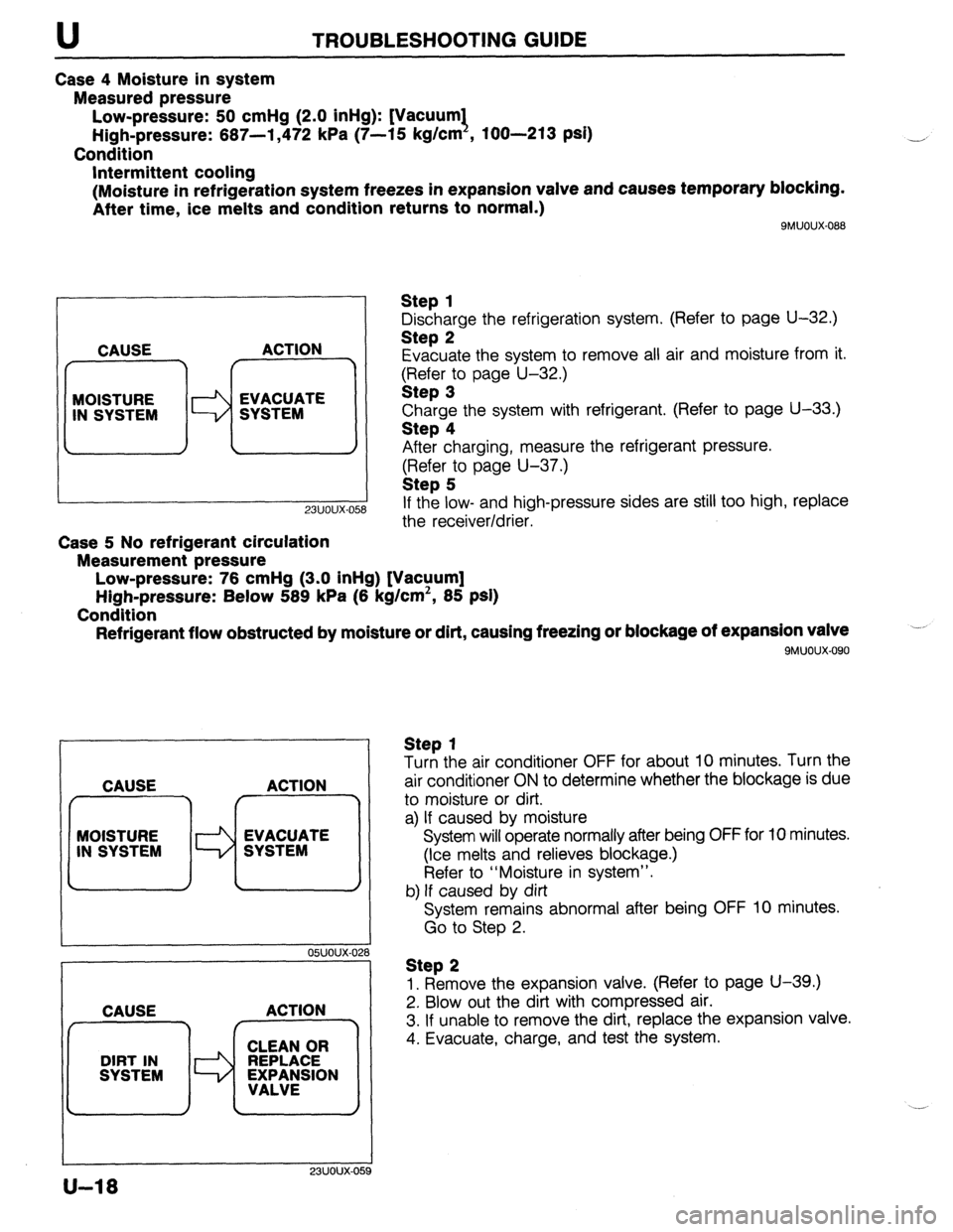
Case 4 Moisture in system
Measured pressure
Low-pressure: 50 cmHg (2.0 inHg): [Vacuum1
High-pressure: 667-l ,472 kPa (7-15 kg/cm , loo-213 psi)
Condition
Intermittent cooling
(Moisture in refrigeration system freezes in expansion valve and causes temporary blocking.
After time, ice melts and condition returns to normal.)
SMUOUX-088
CAUSE ACTION
7 r
MOISTURE
IN SYSTEM WW;MTE
-
23uoux-O!
Case 5 No refrigerant circulation
Measurement pressure
Low-pressure: 76 cmHg (3.0 inHg) [Vacuum]
High-pressure: Below 589 kPa (6 kg/cm’, 85 psi)
Condition
Refrigerant flow obstructed by moisture or dirt, causing freezing or blockage of expansion valve
9MUOUX.090
Step 1
Discharge the refrigeration system, (Refer to page U-32.)
Step 2
Evacuate the system to remove all air and moisture from it.
$?&$r:o page U-32.)
Charge the system with refrigerant. (Refer to page U-33.)
Step 4
After charging, measure the refrigerant pressure.
(Refer to page U-37.)
Step 5
If the low- and high-pressure sides are still too high, replace
the receiver/drier.
CAUSE ACTION
f r^‘---7
MOISTURE
Id EVACUATE
IN SYSTEM SYSTEM
I I
05UOUX-02
CAUSE ACTION
23UOUX-OE
Step 1
Turn the air conditioner OFF for about 10 minutes. Turn the
air conditioner ON to determine whether the blockage is due
to moisture or dirt.
a) If caused by moisture
System will operate normally after being OFF for 10 minutes.
(Ice melts and relieves blockage.)
Refer to “Moisture in system”.
b) If caused by dirt
System remains abnormal after being OFF 10 minutes.
Go to Step 2.
Step 2
1. Remove the expansion valve. (Refer to page U-39.)
2. Blow out the dirt with compressed air.
3. If unable to remove the dirt, replace the expansion valve.
4. Evacuate, charge, and test the system.
U-18