1989 MAZDA 323 turn signal
[x] Cancel search: turn signalPage 891 of 1164
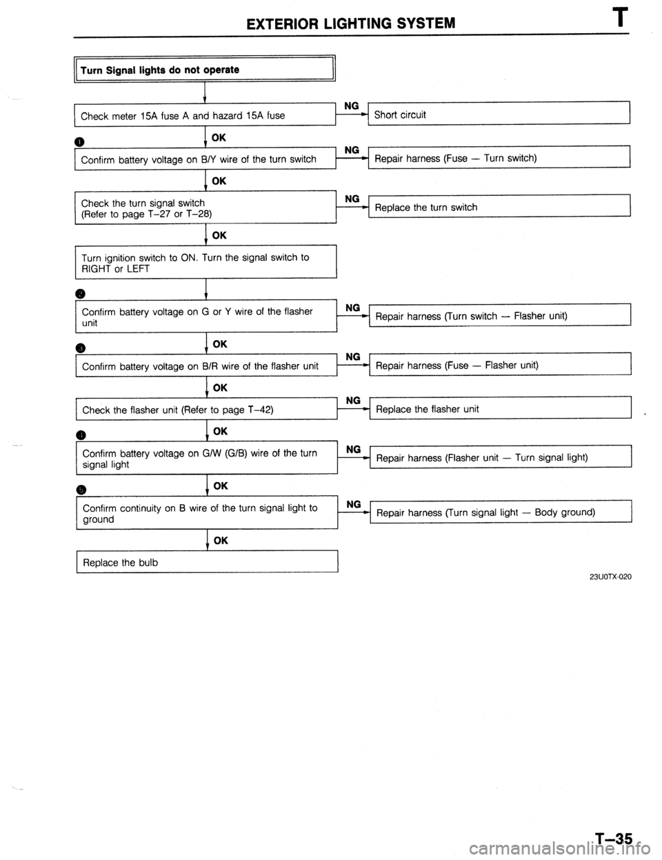
EXTERIOR LIGHTING SYSTEM
Turn Signal lights do not operate
Check meter 15A fuse A an
I
0 OK
Confirm battery voltage on BI Repair harness (Fuse - Turn switch) OK
1 ~,-
Check the turn signal switch NG
(Refer to page T-27 or T-28) Replace the turn switch
1 OK
Turn ignition switch to ON. Turn the signal switch to
RIGHT or LEFT
Confirm battery voltage on G or Y wire of the flasher
unit Repair harness (Turn switch - Flasher unit)
6) OK
Confirm battery voltage on B Repair harness (Fuse - Flasher unit)
1
1 OK
Check the flasher unit (Refe Replace the flasher unit
I
(B OK
Confirm battery voltage on G/W (G/B) wire of the turn
signal light NG _
Repair harness (Flasher unit - Turn signal light) @ OK
Confirm continuity on B wire of the turn signal light to
ground OK
Replace the bulb NG
Repair harness (Turn signal light - Body ground)
23UOTX-020
T-35
Page 892 of 1164
I
EXTERIOR LIGHTING SYSTEM
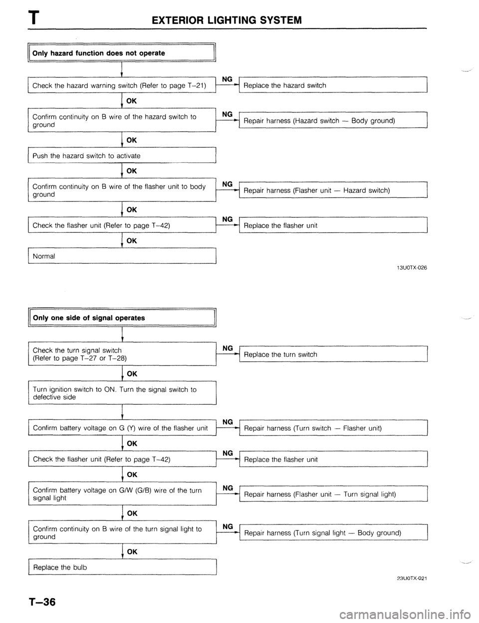
Only hazard function does not operate
Check the hazard warning Replace the hazard switch
1 I
1 OK
Confirm continuity on B wire of the hazard switch to
ground Repair harness (Hazard switch - Body ground)
OK
I I
Push the hazard switch to activate
OK -2
Confirm continuity on B wire of the flasher unit to body
ground NG
Repair harness (Flasher unit - Hazard switch)
OK
NG
Check the flasher unit (Refer
Replace the flasher unit
Normal
I
Only one side of signal operates
13UOTX-026 .,
Check the turn signal switch
(Refer to page T-27 or T-28)
I Replace the turn switch
1 OK
Turn ignition switch to ON. Turn the signal switch to
defective side
Repair harness (Turn switch - Flasher unit)
Replace the flasher unit
Confirm battery voltage on G/W (G/B) wire of the turn
signal light NG-
- Repair harness (Flasher unit - Turn signal light)
I OK
Confirm continuity on B wire of the turn signal light to
ground NG
Repair harness (Turn signal light - Body ground)
Replace the bulb
T-36
I OK
23UOTX-021
Page 937 of 1164

CRUISE CONTROL SYSTEM T
L 23UOTX-05
Condition Code Numbers
Self-diagnosis of malfunction
The test light will flash if a malfunction is present.
Inspection Procedure
Self-diagnosis of malfunction
1. Locate the cruise control connector.
2. Connect a 1.4W test light between terminals f and d, with
connector attached to control unit.
Note
l There is no wire in terminal d of the connector. Push
the test light through the connector and touch the
corresponding pin on the control unit.
3. Turn the ignition switch to ON.
4. Turn the cruise control on by pressing the MAIN switch. (The
MAIN indicator lamp will come ON.)
5. Press and hold the RESUMElACCEL switch for more than
three second.
6. The test light will illuminate for 3 seconds and go out for
2 seconds.
7. The self-diagnostic system is activated and the test light will
flash if a problem is present.
8. Make note of the condition code number(s).
(Refer to the chart at the bottom of the page).
9. After retrieving the code(s), drive the vehicle at more than
16 km/h (lOmph), or press the MAIN switch to deactivate
self-diagnosis. (The MAIN indicator lamp will go OFF.)
Note
l The cruise control system will not operate when in
the self-diagnosis mode.
Pattern of output signal
(Test light)
ON
OFF ON
GFF
,“r,- ON
OFF Note
23UOTX-05
l
If there is more than one malfunction, the code numbers will be indicated in numerical order.
T-81 Code
No.
01
05 Possible Cause Action
Defective wiring (Actuator-Cruise control
unit, Stoplight switch-Cruise control unit)
Defective actuator
Defective stoplight switch (For cruise)
STOP fuse blown
Defective wiring (Fuse - Cruise control
unit)
Both stoplight switches (for vehicle and
cruise) are ON simultaneously
Defective SET/COAST. or RESUME/ Inspect cruise control switch
ACCEL switch (Refer to page T-21)
Defective cruise control unit Repair harness
Inspect actuator
(Refer to page T-87)
Inspect stoplight switch
(Refer to page T-87)
Replace fuse
Repair harness
Inspect stoplight switches
(Refer to pages T-47 and
T-87)
Go to troubleshooting
(Refer to page T-83)
Page 938 of 1164
CRUISE CONTROL SYSTEM
I
23UOTX-056
1 23UOTX-057
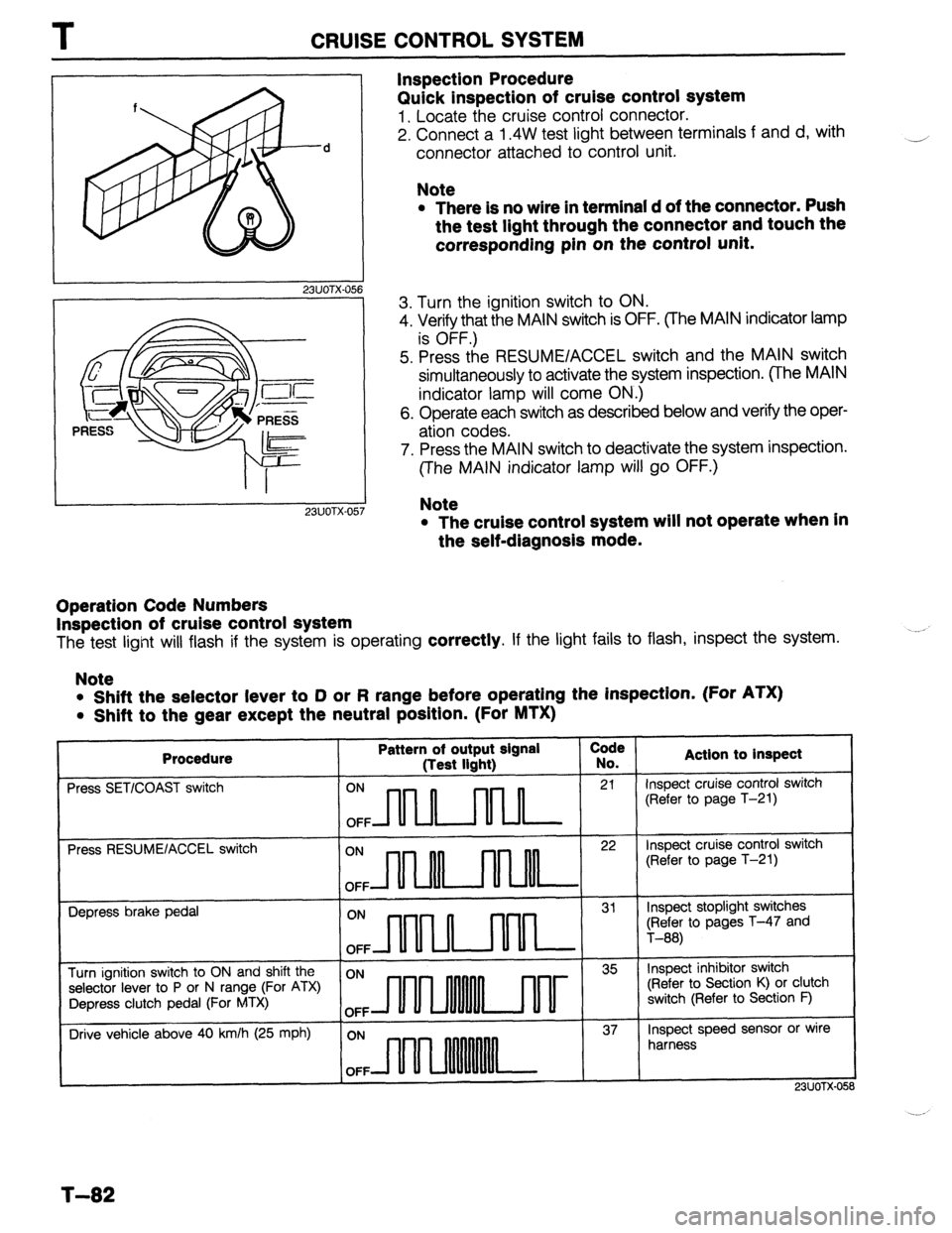
Inspection Procedure
Quick inspection of cruise control system
1. Locate the cruise control connector.
2. Connect a 1.4W test light between terminals f and d, with
connector attached to control unit. -1
Note
l There is no wire in terminal d of the connector. Push
the test light through the connector and touch the
corresponding pin on the control unit.
3. Turn the ignition switch to ON.
4. Verify that the MAIN switch is OFF. (The MAIN indicator lamp
is OFF.)
5. Press the RESUMElACCEL switch and the MAIN switch
simultaneously to activate the system inspection. (The MAIN
indicator lamp will come ON.)
6. Operate each switch as described below and verify the oper-
ation codes.
7. Press the MAIN switch to deactivate the system inspection.
(The MAIN indicator lamp will go OFF.)
Note
l The cruise control system will not operate when in
the self-diagnosis mode.
Operation Code Numbers
Inspection of cruise control system
The test light will flash if the system is operating correctly. If the light fails to flash, inspect the system.
Note
l Shift the selector lever to D or R range before operating the inspection. (For ATX)
l Shift to the gear except the neutral position. (For MTX)
Procedure
Press SET/COAST switch Pattern of output signal Code
(Test light) No. Actlon to inspect ON
n II 21 Inspect cruise control switch
(Refer to page T-21)
OFF
Press RESUMElACCEL switch
ON
n 22 inspect cruise control switch
(Refer to page T-21)
OFF
Depress brake pedal
ON
n ml 31 Inspect stoplight switches
(Refer to pages T-47 and
OFF T-88)
Turn ignition switch to ON and shift the ON 35 Inspect inhibitor switch
selector lever to P or N range (For ATX) (Refer to Section K) or clutch
Depress clutch pedal (For MTX) switch (Refer to Section F)
OFF
Drive vehicle above 40 km/h (25 mph) ON 37 Inspect speed sensor or wire
harness
OFF
I
1
. . . _
T-82
Page 953 of 1164
AUDIO T
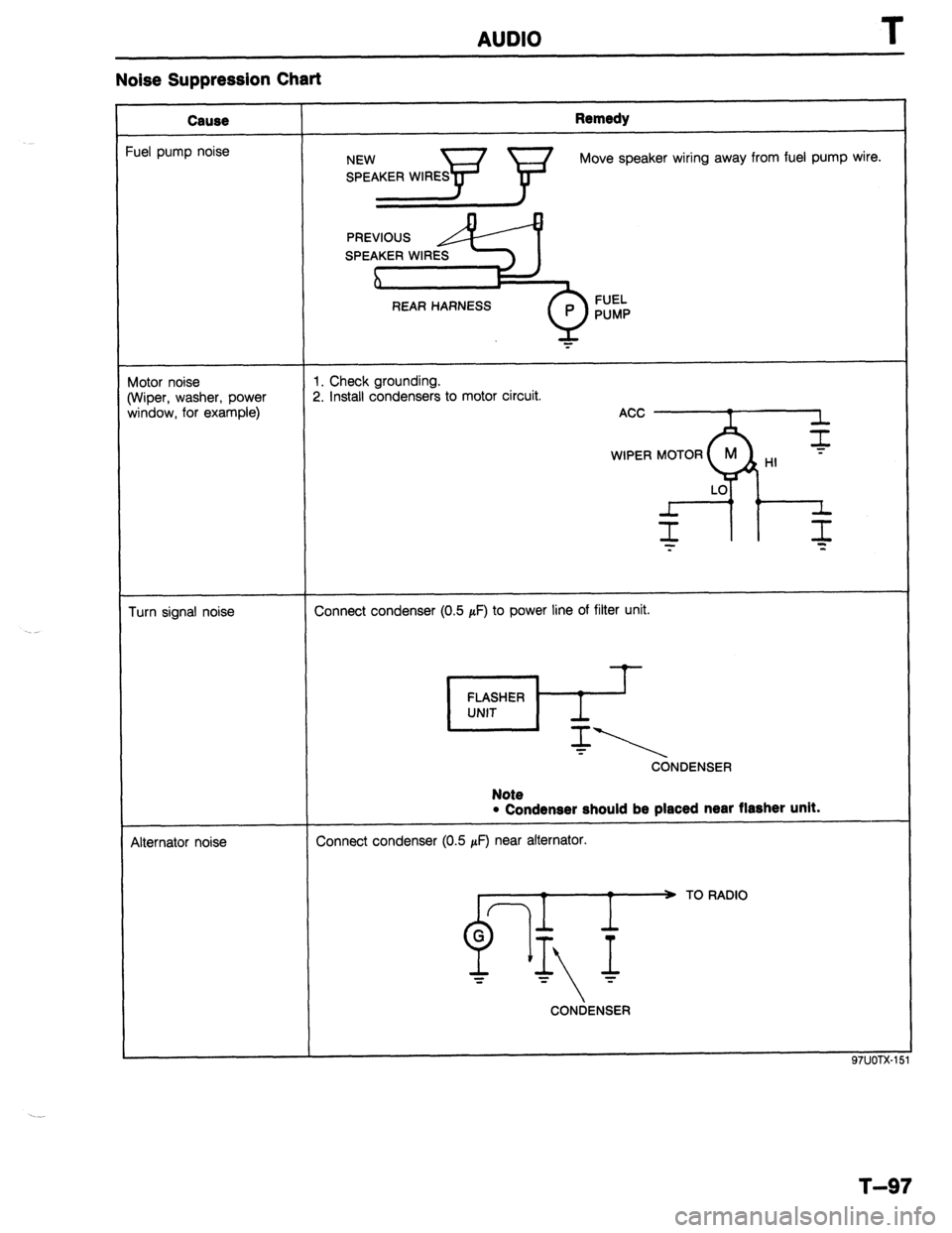
Noise Suppression Chart
Cause
‘uel pump noise Remedy Move speaker wiring away from fuel pump wire.
REAR HARNESS FUEL
PUMP
Wotor noise
Wiper, washer, power
window, for example) 1. Check grounding.
2. Install condensers to motor circuit.
Turn signal noise Connect condenser (0.5 pF) to power line of filter unit. Note
CONDENSER
4lternator noise
l Condenser should be placed near flasher unit.
Connect condenser (0.5 pF) near alternator.
TO RADIO
CONDENSER
97UOTX-1
T-97
Page 1066 of 1164
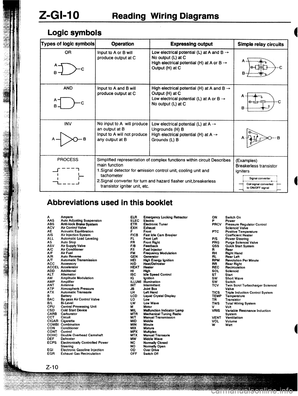
Z-GI-10 Reading Wiring Diagrams
Logic symbols
‘ypes of logic symbols Operation Expressing output Simple relay circuits
OR Input to A or 6 will Low electrical potential (L) at A and B --,
produce output at C No output (L) at C
High electrical potential (H) at A or B -+ A
A
ID- C Output (H) at C
EB Q-f2 c
B B
AND Input to A and B will High electrical potential (H) at A and B -+
produce output at C Output (H) at C
A _
A
El-- Low electrical potential (L) at A or B -+
B C
No output (L) at C
B
II!I3 Q-00-Q
C
INV No input to A will produce Low electrical potential (L) at A +
an output at B
Ungrounds (H) B
-b- Input to A will not produce High electrical potential (H) at A +
A B
any output at B Grounds (L) B A-
El
PROCESS Simplified representation of complex functions within circuit Describes (Examples)
main function
Breakerless transistor
---
-I- 1 1 Signal detector for emission control unit, cooling unit and
I igniters
- ~._..._...._._..._._..__,
--L--A tachometer
P.Signal converter for turn and hazard flasher unit,breakerless : siinalcon”elter :
i..-.--...-.........---i
transistor igniter unit, etc. --j CoIlsignal ConVerted e
--I. .‘p. Y?YT?!!9’. . _ i
Abbreviations used in this booklet
A
%J Ampere
Auto Stop
Air Supply Valve
A/C AAS
Air Conditioner Auto Adjusting Suspension
A/F Air Fuel ABS
AIR Anti-lock Brake System
Auto Reverse
A/T ACV
Automatic Transmission
ACC Air Control Vafve
Acc%K4tIory
ACCEL Accelerator
ADD AE
Additional Acoustic Equilibration
ALT Alternator
EP AIS
Amplitude Modulation Air Injection System
Amplifier ALL
ANT Antenna Automatic Load Levelino
ATP Atmospheric Pressure
ATX Automatic Tmnsaxle FR Fmnt Right ELI?
FIB Feedback
F/I Fuel Injector Emergency Locking Retractor
EN ELEC Electric
Frequency Modulation
Generator
HEI Electronic Tuner
Hiih Energy lgnitiin
HID K!
Heat/Defmster
HEAT Heater Exhaust
HI Hiih F
ISC Front
Idk Speed Contml
IG Ignition
ILLUMI Illumination FICB
INT Intermittent FL Fast Idle Cam Breaker
Fmnt Left
JB
LH Joint Box
Left Hand
:AC Battery
Bypass Air Control Valve
B/L Ei-Level
CPU Central Pmcessing Unit
CSD COM start Device
CARB Carburator
CCT Circuit
CIGAR Cigarette
COMBI Combination
CON Conditioner
CONT Control
DOHC Double Overhead Camshaft
DEF Defroster
ECPS Electronicalfy Controlfed Power
Steering
EGI Electronic Gasoline Injection
EGR Exhaust Gas Recirculation LCD Liquid Crystal Display
:i Low
Low Wave
/IL Motor
MaWunction Indicator Lamp
MTR Mechanical Tuning Radio
Mrr Manual Transmission
MID Mkfdk,
MIN Minute
MIX
MiXtUt MPX Mukiplex
MTX Manual Transaxte
K Middle Wave
Normalty Closed
too Normally Open
Over Drive
OFF Switch Off ON
FRCV
PTC
P/S
PRG
ass
ii:
RPM
EC
SOL
ST
Et TCV
TICS
TEMP
ES
V
VRIS
VENT
VOL
W Switch On
Power
Pressure Regulator Control
Solenoid Valve
Positiie Temperature
Coefficiint Heater
Power Steering
Purge Solenoid Vahe
Quick Start System
Rear
Riiht Hand
Rear Left
Revolution Per Minute
Rear Right
Recirculation
Solenoid
Start
Short Wave
Switch
~;eScml Turbocharger Solenoid
Triple Induction Control System
Temperature
Transistor
Total Wiring System
volt
Variable Resonance Induction
System
Ventilation
Volume
Wan
Page 1096 of 1164
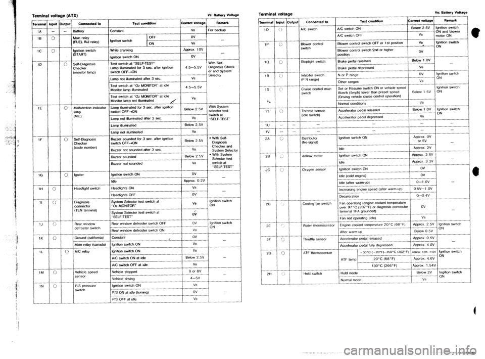
Terminal vdt
wminal lrput
1A -
1B 0
-
1C 0
1D e (ATX) ve: aattefy voltage
1
Connected to
I Test wndition ~cwrect rc4t.gej F&W*
-
0
-
-
3attery
Uain r&y
:FUEL INJ relay) Constant
tgnition swdch V% For backt@
OFF ov
ON V6
Ignition swtch
(START)
Self-Diagnosis
Checker
[monitor lamp)
3 - White crankii npprox 1ov
fgnition switch ON ov
Test swtch at “SELF-TEST’ With Self-
Lamp illuminated for 3 sec. after igmtmn 4.5-5.w Diagnosis Check-
switch OFF-+ON er and System
Selector
Lamp net illuminated after 3 Sec. VS
Test swtch at “02 MONITOR” at idle
i Monitor lamp illuminated 4.5-55v
Test switch at “02 MONtTOR” at idfe
Monitor lamp not illuminated
Malfunction indicator
lamp illuminated for 3 sec. after ignition
Below 2 5v With System
lalllp switch OFF+ON selector test
WLI switch at
Lamp not luminated after 3 sec. VE
“SELF-TEST”
lamp ifluminated BelOW 2.w
Lamp not illuminated VS
Self-Diagnosis Buzzer sounded for 3 sec. after ignrtion
l With Self-
Checker switch OFF-+ON Below 2.5V
Diagm!3s
(code number) Checker and
Buzzer not sounded after 3 set VB
system
Select0 Buzzer sou&?d Below 2 5v l With System
Selector test
I Buzzer not sounded
tgmter Ignition switch ON ov
Idle Appror 0 2v -
Headlight switch Headlights ON
f VB
-
Headlbhts OFF ! ov
Diagnosis
connector
, System Selector test switch at
VS Ignition witch
“02 MONITOR” ON
(TEN terminal)
Rear window
defroster switch
Ground Icalifornia) System Selector tesf switch at
“SELF-TEST”
Rear window defroster watch OFF
Rear window de!roster watch ON
ConSlant QV
ov lgmhon switch
__ ON
VO
ov
- Main relay (canadal fgmtion switch ON VB
AC relay Ignitiin switch ON VB
A/C switch ON at Idle Below 2.5% -
Vehicle speed A/C switch OFF at Gle
/ Vehicle stopped
P/S pressure
switch lgmhon switch ON
P/S ON at idle Iturnino)
I.
P/S OFF at idle I VB Terminal voltage v‘s: Battery vottage
I I
1
Terminal input Output Connected to Test condition comcl voltage Remark
10
0 A/C swatch AIC switch ON Befow25V ignition switch
ON and blower
A/C switch OFF VB I
motor ON
IP
ii Blower control Blower control swtch OFF or 1 St poSItion VB tgnibon switch
switch ON
Blower control switch 2nd or higher
ov
position
1Q
0 Stopltght switch Brake pedal released Below 1 ov
-
IT <; Brake pedal depressed VE
lnhtbitor switch N or P range ov Ignition switch
(P N range) ON
Other ranges VB
Cruise control man Set or Resume swtch ON or vehicle speed lgmhon swtch
switch 8kmih &mph) lower than preset speed &tow 1 5~ ON
(Drwng vehcfe crwse cantrol
OperatiOn)
Fk
z 1v -
3A ’ Throttle Sensor
(Idle switch) Normal conditions
Accelerator pedal released
Accelerator pedal depressed “8
Bebw 1 ov lgnihon swatch
ON
VS
I -
-
- - -
-
-
- - -
D&rib&r
-‘. / b / / (Ne-signal) lgmtion swtch ON
/ ,,,, Approx. OV
or 5v
-
Approx 2v
I ._.
/
28 1
AdlOw meter lgmhon switch ON
Approx 3 BV .,
-
Idle Approx 3 3V
2c j r:
I \’ oxygen sensor fgmtson switch ON ov
1
20 Idle (cold englIIei
Idle (after warn-up)
lncreasma enwe speed (after warm-up) ov
O-l ov -
0 w-1 .ov
_ -
,
Deceleration o-o 4v
Coolmg fan swtch Fan operahng (engine coolant temperature
over 97°C (207’F) or diagnosis connector DV
termmat TFA grounded) -
Fan not operatmg (idle)
Water thermosensor Engine codant temperature L” %, I”” I , ‘Y”8’.“” . . . ...-1.
After warm-up
I
Thrnttb SP”SOi 1 Accelerator pedal released Approx 0.5V
2G .._..._ --..--
-
Accelerator pedal fully depressed Approx. 4 OV
0 ATF thermosensor -XPC (-2o”~)--1x1~c (302°F) aprxox as5-~m lgmhon swtch
ON
ATF temp 20°C (68°F) Approx. 4.6V
13OOC (266°F) Aporox 1.54V
I I I I I I
2H / i, I / Hold switch Hold mode Below 2V Ingbhon switch
Normal mode