1989 FORD FIESTA battery
[x] Cancel search: batteryPage 32 of 296
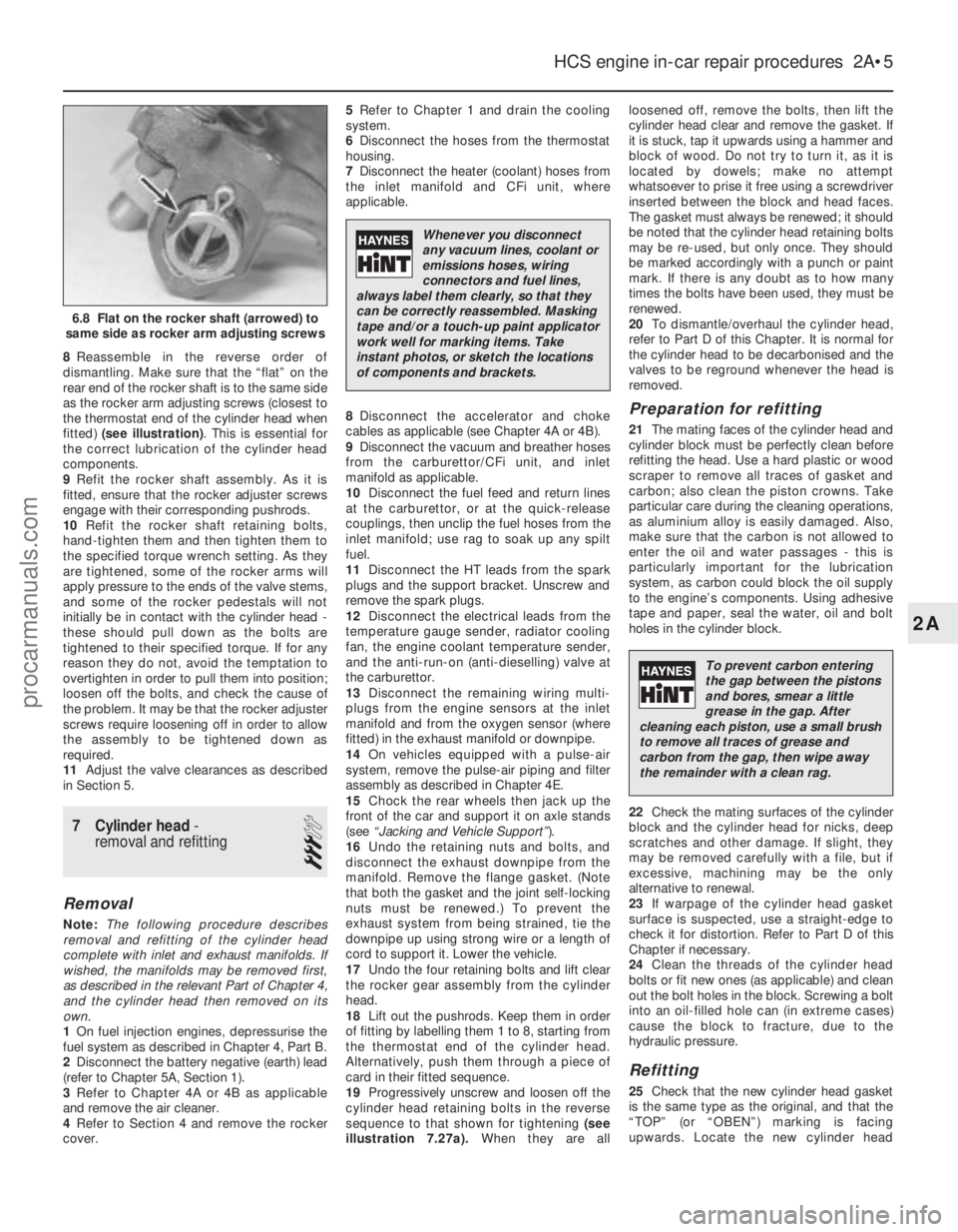
8Reassemble in the reverse order of
dismantling. Make sure that the “flat” on the
rear end of the rocker shaft is to the same side
as the rocker arm adjusting screws (closest to
the thermostat end of the cylinder head when
fitted) (see illustration) . This is essential for
the correct lubrication of the cylinder head
components.
9 Refit the rocker shaft assembly. As it is
fitted, ensure that the rocker adjuster screws
engage with their corresponding pushrods.
10 Refit the rocker shaft retaining bolts,
hand-tighten them and then tighten them to
the specified torque wrench setting. As they
are tightened, some of the rocker arms will
apply pressure to the ends of the valve stems,
and some of the rocker pedestals will not
initially be in contact with the cylinder head -
these should pull down as the bolts are
tightened to their specified torque. If for any
reason they do not, avoid the temptation to
overtighten in order to pull them into position;
loosen off the bolts, and check the cause of
the problem. It may be that the rocker adjuster
screws require loosening off in order to allow
the assembly to be tightened down as
required.
11 Adjust the valve clearances as described
in Section 5.
7 Cylinder head -
removal and refitting
3
Removal
Note: The following procedure describes
removal and refitting of the cylinder head
complete with inlet and exhaust manifolds. If
wished, the manifolds may be removed first,
as described in the relevant Part of Chapter 4,
and the cylinder head then removed on its
own.
1 On fuel injection engines, depressurise the
fuel system as described in Chapter 4, Part B.
2 Disconnect the battery negative (earth) lead
(refer to Chapter 5A, Section 1).
3 Refer to Chapter 4A or 4B as applicable
and remove the air cleaner.
4 Refer to Section 4 and remove the rocker
cover. 5
Refer to Chapter 1 and drain the cooling
system.
6 Disconnect the hoses from the thermostat
housing.
7 Disconnect the heater (coolant) hoses from
the inlet manifold and CFi unit, where
applicable.
8 Disconnect the accelerator and choke
cables as applicable (see Chapter 4A or 4B).
9 Disconnect the vacuum and breather hoses
from the carburettor/CFi unit, and inlet
manifold as applicable.
10 Disconnect the fuel feed and return lines
at the carburettor, or at the quick-release
couplings, then unclip the fuel hoses from the
inlet manifold; use rag to soak up any spilt
fuel.
11 Disconnect the HT leads from the spark
plugs and the support bracket. Unscrew and
remove the spark plugs.
12 Disconnect the electrical leads from the
temperature gauge sender, radiator cooling
fan, the engine coolant temperature sender,
and the anti-run-on (anti-dieselling) valve at
the carburettor.
13 Disconnect the remaining wiring multi-
plugs from the engine sensors at the inlet
manifold and from the oxygen sensor (where
fitted) in the exhaust manifold or downpipe.
14 On vehicles equipped with a pulse-air
system, remove the pulse-air piping and filter
assembly as described in Chapter 4E.
15 Chock the rear wheels then jack up the
front of the car and support it on axle stands
(see “Jacking and Vehicle Support” ).
16 Undo the retaining nuts and bolts, and
disconnect the exhaust downpipe from the
manifold. Remove the flange gasket. (Note
that both the gasket and the joint self-locking
nuts must be renewed.) To prevent the
exhaust system from being strained, tie the
downpipe up using strong wire or a length of
cord to support it. Lower the vehicle.
17 Undo the four retaining bolts and lift clear
the rocker gear assembly from the cylinder
head.
18 Lift out the pushrods. Keep them in order
of fitting by labelling them 1 to 8, starting from
the thermostat end of the cylinder head.
Alternatively, push them through a piece of
card in their fitted sequence.
19 Progressively unscrew and loosen off the
cylinder head retaining bolts in the reverse
sequence to that shown for tightening (see
illustration 7.27a). When they are all loosened off, remove the bolts, then lift the
cylinder head clear and remove the gasket. If
it is stuck, tap it upwards using a hammer and
block of wood. Do not try to turn it, as it is
located by dowels; make no attempt
whatsoever to prise it free using a screwdriver
inserted between the block and head faces.
The gasket must always be renewed; it should
be noted that the cylinder head retaining bolts
may be re-used, but only once. They should
be marked accordingly with a punch or paint
mark. If there is any doubt as to how many
times the bolts have been used, they must be
renewed.
20
To dismantle/overhaul the cylinder head,
refer to Part D of this Chapter. It is normal for
the cylinder head to be decarbonised and the
valves to be reground whenever the head is
removed.
Preparation for refitting
21 The mating faces of the cylinder head and
cylinder block must be perfectly clean before
refitting the head. Use a hard plastic or wood
scraper to remove all traces of gasket and
carbon; also clean the piston crowns. Take
particular care during the cleaning operations,
as aluminium alloy is easily damaged. Also,
make sure that the carbon is not allowed to
enter the oil and water passages - this is
particularly important for the lubrication
system, as carbon could block the oil supply
to the engine’s components. Using adhesive
tape and paper, seal the water, oil and bolt
holes in the cylinder block.
22 Check the mating surfaces of the cylinder
block and the cylinder head for nicks, deep
scratches and other damage. If slight, they
may be removed carefully with a file, but if
excessive, machining may be the only
alternative to renewal.
23 If warpage of the cylinder head gasket
surface is suspected, use a straight-edge to
check it for distortion. Refer to Part D of this
Chapter if necessary.
24 Clean the threads of the cylinder head
bolts or fit new ones (as applicable) and clean
out the bolt holes in the block. Screwing a bolt
into an oil-filled hole can (in extreme cases)
cause the block to fracture, due to the
hydraulic pressure.
Refitting
25 Check that the new cylinder head gasket
is the same type as the original, and that the
“TOP” (or “OBEN”) marking is facing
upwards. Locate the new cylinder head
HCS engine in-car repair procedures 2A•5
6.8 Flat on the rocker shaft (arrowed) to
same side as rocker arm adjusting screws
2A
1595Ford Fiesta Remake
Whenever you disconnect
any vacuum lines, coolant or
emissions hoses, wiring
connectors and fuel lines,
always label them clearly, so that they
can be correctly reassembled. Masking
tape and/or a touch-up paint applicator
work well for marking items. Take
instant photos, or sketch the locations
of components and brackets.
To prevent carbon entering
the gap between the pistons
and bores, smear a little
grease in the gap. After
cleaning each piston, use a small brush
to remove all traces of grease and
carbon from the gap, then wipe away
the remainder with a clean rag.
procarmanuals.com
http://vnx.su
Page 33 of 296
gasket onto the top face of the cylinder block
and over the dowels. Ensure that it is correctly
aligned with the coolant passages and
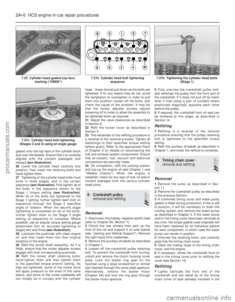
oilways (see illustration) .
26 Lower the cylinder head carefully into
position, then insert the retaining bolts and
hand-tighten them.
27 Tightening of the cylinder head bolts must
done in three stages, and in the correct
sequence (see illustration) . First tighten all of
the bolts in the sequence shown to the
Stage 1 torque setting (see illustration).
When all of the bolts are tightened to the
Stage 1 setting, further tighten each bolt (in
sequence) through the Stage 2 specified
angle of rotation. When the second stage
tightening is completed on all of the bolts,
further tighten them to the Stage 3 angle
setting (in sequence) to complete. Where
possible, use an angular torque setting gauge
attachment tool for accurate tightening of
stages two and three (see illustration).
28 Lubricate the pushrods with clean engine
oil, and then insert them into their original
locations in the engine.
29 Refit the rocker shaft assembly. As it is
fitted, ensure that the rocker adjuster screws
engage with their corresponding pushrods.
30 Refit the rocker shaft retaining bolts,
hand-tighten them and then tighten them
to the specified torque wrench setting. As
they are tightened, some of the rocker arms
will apply pressure to the ends of the valve
stems, and some of the rocker pedestals will
not initially be in contact with the cylinder head - these should pull down as the bolts are
tightened. If for any reason they do not, avoid
the temptation to overtighten in order to pull
them into position; loosen off the bolts, and
check the cause of the problem. It may be
that the rocker adjuster screws require
loosening off in order to allow the assembly to
be tightened down as required.
31
Adjust the valve clearances as described
in Section 5.
32 Refit the rocker cover as described in
Section 4.
33 The remainder of the refitting procedure is
a reversal of the removal process. Tighten all
fastenings to their specified torque setting
(where given). Refer to the appropriate Parts
of Chapter 4 for details on reconnecting the
fuel and exhaust system components. Ensure
that all coolant, fuel, vacuum and electrical
connections are securely made.
34 On completion, refill the cooling system
and top-up the engine oil (see Chapter 1 and
“Weekly Checks” ). When the engine is
restarted, check for any sign of fuel, oil and/or
coolant leakages from the various cylinder
head joints.
8 Crankshaft pulley -
removal and refitting
2
Removal
1 Disconnect the battery negative (earth) lead
(refer to Chapter 5A, Section 1).
2 Chock the rear wheels then jack up the
front of the car and support it on axle stands
(see “Jacking and Vehicle Support” ). Remove
the right-hand front roadwheel.
3 Remove the auxiliary drivebelt as described
in Chapter 1.
4 Loosen off the crankshaft pulley retaining
bolt. To prevent the crankshaft from turning,
unbolt and remove the clutch housing cover
plate. Lock the starter ring gear on the
flywheel using a large screwdriver or similar
tool inserted through the cover plate aperture.
Alternatively, remove the starter motor
(Chapter 5A) and lock the ring gear through
the starter motor aperture. 5
Fully unscrew the crankshaft pulley bolt,
and withdraw the pulley from the front end of
the crankshaft. If it does not pull off by hand,
lever it free using a pair of suitable levers
positioned diagonally opposite each other
behind the pulley.
6 If required, the crankshaft front oil seal can
be renewed at this stage, as described in
Section 14.
Refitting
7 Refitting is a reversal of the removal
procedure ensuring that the pulley retaining
bolt is tightened to the specified torque
setting.
8 Refit the auxiliary drivebelt as described in
Chapter 1, and lower the vehicle to complete.
9 Timing chain cover -
removal and refitting
2
Removal
1 Remove the sump as described in Sec-
tion 11.
2 Remove the crankshaft pulley as described
in the previous Section.
3 A combined timing cover and water pump
gasket is fitted during production; if this is still
in position, it will be necessary to drain the
cooling system and remove the water pump
as described in Chapter 3. If the water pump
and/or the timing cover have been removed at
any time, the single gasket used originally will
have been replaced by an individual gasket
for each component, in which case the water
pump can remain in position.
4 Unscrew the retaining bolts, and carefully
prise free the timing chain cover.
5 Clean the mating faces of the timing chain
cover, and the engine.
6 If necessary, renew the crankshaft front oil
seal in the timing cover prior to refitting the
cover (see Section 14).
Refitting
7 Lightly lubricate the front end of the
crankshaft and the radial lip of the timing
chain cover oil seal (already installed in the
2A•6 HCS engine in-car repair procedures
7.27c Cylinder head bolt tightening
(Stages 2 and 3) using an angle gauge
7.27b Tightening the cylinder head bolts (Stage 1)7.27a Cylinder head bolt tighteningsequence7.25 Cylinder head gasket top-facemarking (“OBEN”)
1595Ford Fiesta Remakeprocarmanuals.com
http://vnx.su
Page 34 of 296
cover). Using a new gasket, fit the timing
chain cover, centring it with the aid of the
crankshaft pulley - lubricate the seal contact
surfaces beforehand. Refit and tighten the
retaining bolts but, where applicable, leave
out the timing cover bolt which also secures
the water pump at this stage.
8Where applicable, refit the water pump as
described in Chapter 3.
9 Refit the crankshaft pulley as described in
the previous Section.
10 Refit the sump as described in Section 11.
10Timing chain, sprockets and
tensioner - removal,
inspection and refitting
3
Removal
1 Remove the timing chain cover as
described in the previous Section.
2 Remove the oil slinger from the front face of
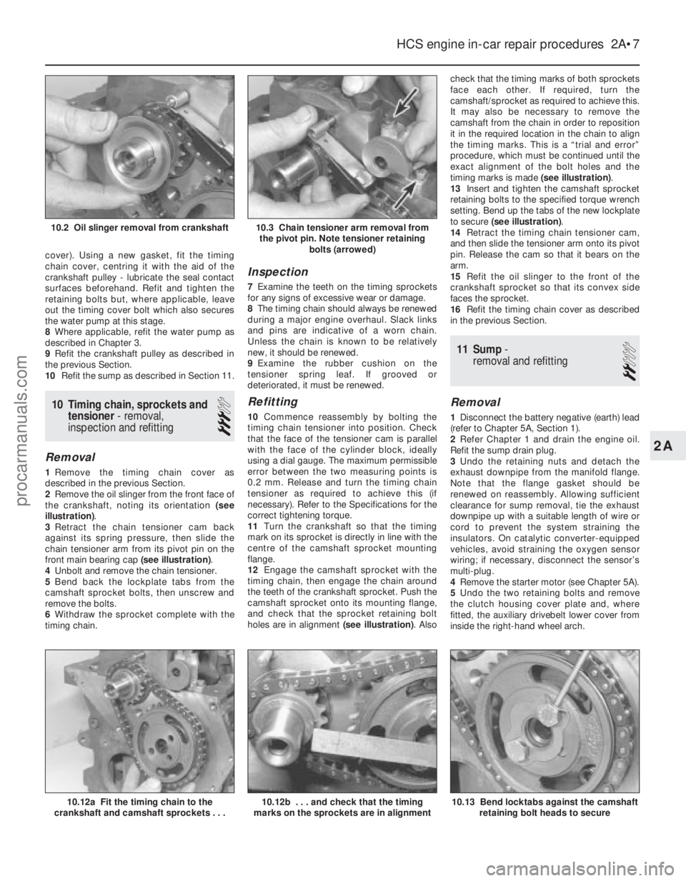
the crankshaft, noting its orientation (see
illustration) .
3 Retract the chain tensioner cam back
against its spring pressure, then slide the
chain tensioner arm from its pivot pin on the
front main bearing cap (see illustration).
4 Unbolt and remove the chain tensioner.
5 Bend back the lockplate tabs from the
camshaft sprocket bolts, then unscrew and
remove the bolts.
6 Withdraw the sprocket complete with the
timing chain.
Inspection
7 Examine the teeth on the timing sprockets
for any signs of excessive wear or damage.
8 The timing chain should always be renewed
during a major engine overhaul. Slack links
and pins are indicative of a worn chain.
Unless the chain is known to be relatively
new, it should be renewed.
9 Examine the rubber cushion on the
tensioner spring leaf. If grooved or
deteriorated, it must be renewed.
Refitting
10 Commence reassembly by bolting the
timing chain tensioner into position. Check
that the face of the tensioner cam is parallel
with the face of the cylinder block, ideally
using a dial gauge. The maximum permissible
error between the two measuring points is
0.2 mm. Release and turn the timing chain
tensioner as required to achieve this (if
necessary). Refer to the Specifications for the
correct tightening torque.
11 Turn the crankshaft so that the timing
mark on its sprocket is directly in line with the
centre of the camshaft sprocket mounting
flange.
12 Engage the camshaft sprocket with the
timing chain, then engage the chain around
the teeth of the crankshaft sprocket. Push the
camshaft sprocket onto its mounting flange,
and check that the sprocket retaining bolt
holes are in alignment (see illustration). Alsocheck that the timing marks of both sprockets
face each other. If required, turn the
camshaft/sprocket as required to achieve this.
It may also be necessary to remove the
camshaft from the chain in order to reposition
it in the required location in the chain to align
the timing marks. This is a “trial and error”
procedure, which must be continued until the
exact alignment of the bolt holes and the
timing marks is made
(see illustration).
13 Insert and tighten the camshaft sprocket
retaining bolts to the specified torque wrench
setting. Bend up the tabs of the new lockplate
to secure (see illustration) .
14 Retract the timing chain tensioner cam,
and then slide the tensioner arm onto its pivot
pin. Release the cam so that it bears on the
arm.
15 Refit the oil slinger to the front of the
crankshaft sprocket so that its convex side
faces the sprocket.
16 Refit the timing chain cover as described
in the previous Section.
11 Sump -
removal and refitting
2
Removal
1 Disconnect the battery negative (earth) lead
(refer to Chapter 5A, Section 1).
2 Refer Chapter 1 and drain the engine oil.
Refit the sump drain plug.
3 Undo the retaining nuts and detach the
exhaust downpipe from the manifold flange.
Note that the flange gasket should be
renewed on reassembly. Allowing sufficient
clearance for sump removal, tie the exhaust
downpipe up with a suitable length of wire or
cord to prevent the system straining the
insulators. On catalytic converter-equipped
vehicles, avoid straining the oxygen sensor
wiring; if necessary, disconnect the sensor’s
multi-plug.
4 Remove the starter motor (see Chapter 5A).
5 Undo the two retaining bolts and remove
the clutch housing cover plate and, where
fitted, the auxiliary drivebelt lower cover from
inside the right-hand wheel arch.
HCS engine in-car repair procedures 2A•7
10.12a Fit the timing chain to the
crankshaft and camshaft sprockets . . .
10.3 Chain tensioner arm removal from the pivot pin. Note tensioner retaining bolts (arrowed)10.2 Oil slinger removal from crankshaft
10.13 Bend locktabs against the camshaftretaining bolt heads to secure10.12b . . . and check that the timing
marks on the sprockets are in alignment
2A
1595Ford Fiesta Remakeprocarmanuals.com
http://vnx.su
Page 35 of 296
6Undo the eighteen bolts securing the sump
to the base of the engine crankcase, then
prise free and lower the sump. If the sump is
stuck tight to the engine, cut around the
flange gasket with a sharp knife, then lightly
tap and prise it free. Keep the sump upright as
it is lowered, to prevent spillage of any
remaining oil in it. Also be prepared for oil
drips from the crankcase when the sump is
removed.
7 Remove any dirt and old gasket from the
contact faces of the sump and crankcase, and
wash the sump out thoroughly before refitting.
Check that the mating faces of the sump are
not distorted. Check that the oil pick-up
strainer is clear, cleaning it if necessary.
Refitting
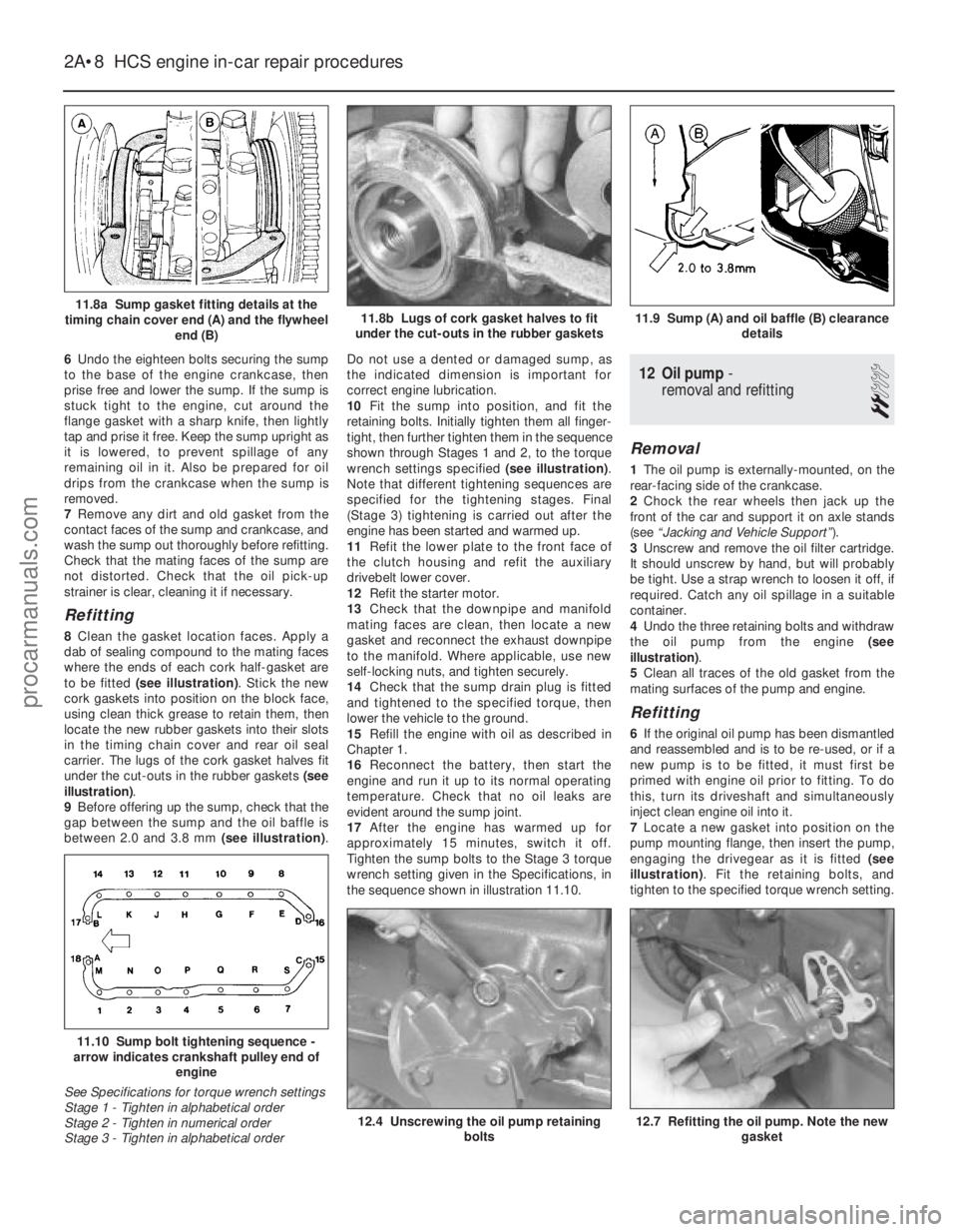
8 Clean the gasket location faces. Apply a
dab of sealing compound to the mating faces
where the ends of each cork half-gasket are
to be fitted (see illustration) . Stick the new
cork gaskets into position on the block face,
using clean thick grease to retain them, then
locate the new rubber gaskets into their slots
in the timing chain cover and rear oil seal
carrier. The lugs of the cork gasket halves fit
under the cut-outs in the rubber gaskets (see
illustration) .
9 Before offering up the sump, check that the
gap between the sump and the oil baffle is
between 2.0 and 3.8 mm (see illustration).Do not use a dented or damaged sump, as
the indicated dimension is important for
correct engine lubrication.
10
Fit the sump into position, and fit the
retaining bolts. Initially tighten them all finger-
tight, then further tighten them in the sequence
shown through Stages 1 and 2, to the torque
wrench settings specified (see illustration).
Note that different tightening sequences are
specified for the tightening stages. Final
(Stage 3) tightening is carried out after the
engine has been started and warmed up.
11 Refit the lower plate to the front face of
the clutch housing and refit the auxiliary
drivebelt lower cover.
12 Refit the starter motor.
13 Check that the downpipe and manifold
mating faces are clean, then locate a new
gasket and reconnect the exhaust downpipe
to the manifold. Where applicable, use new
self-locking nuts, and tighten securely.
14 Check that the sump drain plug is fitted
and tightened to the specified torque, then
lower the vehicle to the ground.
15 Refill the engine with oil as described in
Chapter 1.
16 Reconnect the battery, then start the
engine and run it up to its normal operating
temperature. Check that no oil leaks are
evident around the sump joint.
17 After the engine has warmed up for
approximately 15 minutes, switch it off.
Tighten the sump bolts to the Stage 3 torque
wrench setting given in the Specifications, in
the sequence shown in illustration 11.10.
12 Oil pump -
removal and refitting
2
Removal
1 The oil pump is externally-mounted, on the
rear-facing side of the crankcase.
2 Chock the rear wheels then jack up the
front of the car and support it on axle stands
(see “Jacking and Vehicle Support” ).
3 Unscrew and remove the oil filter cartridge.
It should unscrew by hand, but will probably
be tight. Use a strap wrench to loosen it off, if
required. Catch any oil spillage in a suitable
container.
4 Undo the three retaining bolts and withdraw
the oil pump from the engine (see
illustration) .
5 Clean all traces of the old gasket from the
mating surfaces of the pump and engine.
Refitting
6 If the original oil pump has been dismantled
and reassembled and is to be re-used, or if a
new pump is to be fitted, it must first be
primed with engine oil prior to fitting. To do
this, turn its driveshaft and simultaneously
inject clean engine oil into it.
7 Locate a new gasket into position on the
pump mounting flange, then insert the pump,
engaging the drivegear as it is fitted (see
illustration) . Fit the retaining bolts, and
tighten to the specified torque wrench setting.
2A•8 HCS engine in-car repair procedures
12.7 Refitting the oil pump. Note the new gasket12.4 Unscrewing the oil pump retaining bolts
11.10 Sump bolt tightening sequence -
arrow indicates crankshaft pulley end of
engine
See Specifications for torque wrench settings
Stage 1 - Tighten in alphabetical order
Stage 2 - Tighten in numerical order
Stage 3 - Tighten in alphabetical order
11.9 Sump (A) and oil baffle (B) clearance details11.8b Lugs of cork gasket halves to fit
under the cut-outs in the rubber gaskets11.8a Sump gasket fitting details at the
timing chain cover end (A) and the flywheel end (B)
1595Ford Fiesta Remakeprocarmanuals.com
http://vnx.su
Page 43 of 296
complete turn, and all the markings should
now align.
7With the engine set at No 1 piston on TDC
compression, refit the crankshaft pulley cover,
lower the vehicle and refit the upper timing
belt cover.
4 Cylinder head rocker cover -
removal and refitting
2
Removal
1 Disconnect the battery negative (earth) lead
(refer to Chapter 5A, Section 1).
2 Remove the air cleaner assembly and air
inlet components as necessary for access as
described in the relevant Part of Chapter 4.
Disconnect the crankcase ventilation hose
from the rocker cover.
3 Remove the timing belt upper cover as
described in Section 7.
4 Referring to the relevant Part of Chapter 4
for details, disconnect the accelerator cable
from the throttle linkage and from the adjuster
bracket above the rocker cover. Position the
cable out of the way.
5 Where applicable, disconnect the choke
cable from the carburettor, referring to
Chapter 4A for details.
6 Unscrew and remove the rocker cover
retaining bolts and washers, then lift the cover
from the cylinder head. Note that a new
rocker cover gasket will be needed on
refitting.
Refitting
7 Before refitting the rocker cover, clean the
mating surfaces of both the cylinder head and
the cover.
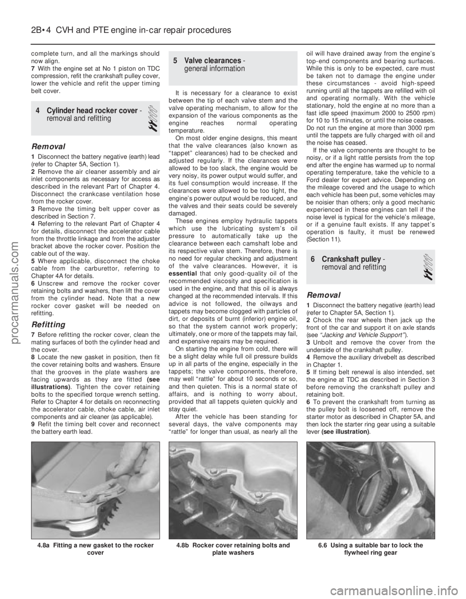
8 Locate the new gasket in position, then fit
the cover retaining bolts and washers. Ensure
that the grooves in the plate washers are
facing upwards as they are fitted (see
illustrations) . Tighten the cover retaining
bolts to the specified torque wrench setting.
Refer to Chapter 4 for details on reconnecting
the accelerator cable, choke cable, air inlet
components and air cleaner (as applicable).
9 Refit the timing belt cover and reconnect
the battery earth lead.
5 Valve clearances -
general information
It is necessary for a clearance to exist
between the tip of each valve stem and the
valve operating mechanism, to allow for the
expansion of the various components as the
engine reaches normal operating
temperature. On most older engine designs, this meant
that the valve clearances (also known as
“tappet” clearances) had to be checked and
adjusted regularly. If the clearances were
allowed to be too slack, the engine would be
very noisy, its power output would suffer, and
its fuel consumption would increase. If the
clearances were allowed to be too tight, the
engine’s power output would be reduced, and
the valves and their seats could be severely
damaged. These engines employ hydraulic tappets
which use the lubricating system’s oil
pressure to automatically take up the
clearance between each camshaft lobe and
its respective valve stem. Therefore, there is
no need for regular checking and adjustment
of the valve clearances. However, it is
essential that only good-quality oil of the
recommended viscosity and specification is
used in the engine, and that this oil is always
changed at the recommended intervals. If this
advice is not followed, the oilways and
tappets may become clogged with particles of
dirt, or deposits of burnt (inferior) engine oil,
so that the system cannot work properly;
ultimately, one or more of the tappets may fail,
and expensive repairs may be required. On starting the engine from cold, there will
be a slight delay while full oil pressure builds
up in all parts of the engine, especially in the
tappets; the valve components, therefore,
may well “rattle” for about 10 seconds or so,
and then quieten. This is a normal state of
affairs, and is nothing to worry about,
provided that all tappets quieten quickly and
stay quiet. After the vehicle has been standing for
several days, the valve components may
“rattle” for longer than usual, as nearly all the oil will have drained away from the engine’s
top-end components and bearing surfaces.
While this is only to be expected, care must
be taken not to damage the engine under
these circumstances - avoid high-speed
running until all the tappets are refilled with oil
and operating normally. With the vehicle
stationary, hold the engine at no more than a
fast idle speed (maximum 2000 to 2500 rpm)
for 10 to 15 minutes, or until the noise ceases.
Do not run the engine at more than 3000 rpm
until the tappets are fully charged with oil and
the noise has ceased.
If the valve components are thought to be
noisy, or if a light rattle persists from the top
end after the engine has warmed up to normal
operating temperature, take the vehicle to a
Ford dealer for expert advice. Depending on
the mileage covered and the usage to which
each vehicle has been put, some vehicles may
be noisier than others; only a good mechanic
experienced in these engines can tell if the
noise level is typical for the vehicle’s mileage,
or if a genuine fault exists. If any tappet’s
operation is faulty, it must be renewed
(Section 11).
6 Crankshaft pulley -
removal and refitting
2
Removal
1 Disconnect the battery negative (earth) lead
(refer to Chapter 5A, Section 1).
2 Chock the rear wheels then jack up the
front of the car and support it on axle stands
(see “Jacking and Vehicle Support” ).
3 Unbolt and remove the cover from the
underside of the crankshaft pulley.
4 Remove the auxiliary drivebelt as described
in Chapter 1.
5 If timing belt renewal is also intended, set
the engine at TDC as described in Section 3
before removing the crankshaft pulley and
retaining bolt.
6 To prevent the crankshaft from turning as
the pulley bolt is loosened off, remove the
starter motor as described in Chapter 5A, and
then lock the starter ring gear using a suitable
lever (see illustration) .
2B•4 CVH and PTE engine in-car repair procedures
6.6 Using a suitable bar to lock the
flywheel ring gear4.8b Rocker cover retaining bolts and plate washers4.8a Fitting a new gasket to the rocker cover
1595Ford Fiesta Remakeprocarmanuals.com
http://vnx.su
Page 44 of 296
7Unscrew and remove the crankshaft pulley
retaining bolt and its washer. Withdraw the
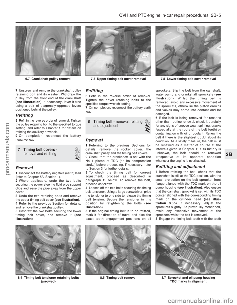
pulley from the front end of the crankshaft
(see illustration) . If necessary, lever it free
using a pair of diagonally-opposed levers
positioned behind the pulley.
Refitting
8 Refit in the reverse order of removal. Tighten
the pulley retaining bolt to the specified torque
setting, and refer to Chapter 1 for details on
refitting the auxiliary drivebelt.
9 On completion, reconnect the battery
negative lead.
7 Timing belt covers -
removal and refitting
1
Removal
1 Disconnect the battery negative (earth) lead
(refer to Chapter 5A, Section 1).
2 Where applicable, undo the two bolts
securing the power steering fluid pipe support
clips and ease the pipe away from the upper
cover.
3 Undo the two retaining bolts and remove
the upper timing belt cover (see illustration).
4 Refer to the previous Section for details,
and remove the crankshaft pulley.
5 Unscrew the two bolts securing the lower
timing belt cover, and remove it (see
illustration) .
Refitting
6Refit in the reverse order of removal.
Tighten the cover retaining bolts to the
specified torque wrench setting.
7 On completion, reconnect the battery earth
lead.
8 Timing belt - removal, refitting
and adjustment
3
Removal
1 Referring to the previous Sections for
details, remove the rocker cover, the
crankshaft pulley and the timing belt covers.
2 Check that the crankshaft is set with the
No 1 piston at TDC (on its compression
stroke) before proceeding. If necessary, refer
to Section 3 for further details.
3 To check the timing belt for correct
adjustment, proceed as described in
paragraph 12 below. To remove the belt,
proceed as follows.
4 Loosen off the two bolts securing the timing
belt tensioner. Using a large screwdriver, prise
the tensioner to one side to release the timing
belt tension. Secure the tensioner in this
position by retightening the bolts (see
illustration) .
5 If the original timing belt is to be refitted,
mark it for direction of travel and also the
exact tooth engagement positions on all sprockets. Slip the belt from the camshaft,
water pump and crankshaft sprockets
(see
illustration) . Whilst the timing belt is
removed, avoid any excessive movement of
the sprockets, otherwise the piston crowns
and valves may come into contact and be
damaged.
6 If the belt is being removed for reasons
other than routine renewal, check it carefully
for any signs of uneven wear, splitting, cracks
(especially at the roots of the belt teeth) or
contamination with oil or coolant. Renew the
belt if there is the slightest doubt about its
condition. As a safety measure, the belt must
be renewed as a matter of course at the
intervals given in Chapter 1; if its history is
unknown, the belt should be renewed
irrespective of its apparent condition
whenever the engine is overhauled.
Refitting and adjustment
7 Before refitting the belt, check that the
crankshaft is still at the TDC position, with the
small projection on the belt sprocket front
flange aligned with the TDC mark on the oil
pump housing (see illustration) . Also ensure
that the camshaft sprocket is set with its TDC
pointer aligned with the corresponding timing
mark on the cylinder head (see illus-
tration 3.6b) . If necessary, adjust the
sprockets slightly. As previously mentioned,
avoid any excessive movement of the
sprockets whilst the belt is removed.
8 Engage the timing belt teeth with the teeth
CVH and PTE engine in-car repair procedures 2B•5
7.5 Lower timing belt cover removal7.3 Upper timing belt cover removal6.7 Crankshaft pulley removal
8.7 Sprocket and oil pump housing
TDC marks in alignment8.5 Timing belt removal8.4 Timing belt tensioner retaining bolts (arrowed)
2B
1595Ford Fiesta Remakeprocarmanuals.com
http://vnx.su
Page 45 of 296
of the crankshaft sprocket, and then pull the
belt vertically upright on its right-hand run.
Keep it taut, and engage it with the teeth of
the camshaft sprocket. If the original belt is
being refitted, check that the belt’s direction
of travel is correct, and realign the belt-to-
sprocket marks made during removal, to
ensure that the exact original engagement
positions are retained. When the belt is fully
fitted on the sprockets, check that the
sprocket positions have not altered.
9Carefully manoeuvre the belt around the
tensioner, and engage its teeth with the water
pump sprocket, again ensuring that the TDC
positions of the crankshaft and camshaft
are not disturbed as the belt is finally
located.
10 Refit the lower timing belt cover, and
tighten its retaining bolts to the specified
torque setting. Refit the crankshaft pulley, and
tighten its retaining bolt to the specified
torque setting.
11 To take up belt slack, loosen off the
tensioner and move it towards the front of the
car to apply an initial tension to the belt.
Secure the tensioner in this position, then
remove the flywheel ring gear locking device.
12 Rotate the crankshaft through two full
revolutions in (the normal direction of travel),
returning to the TDC position (camshaft
sprocket-to-cylinder head). Check that the
crankshaft pulley notch is aligned with the
TDC (0) mark on the lower half of the timing
belt cover.
13 Grasp the belt between the thumb and
forefinger, at the midway point between the
crankshaft and camshaft sprockets on the
right-hand side. If the belt tension is correct, it
should just be possible to twist the belt
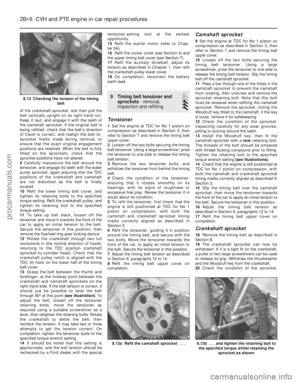
through 90º at this point (see illustration). To
adjust the belt, loosen off the tensioner
retaining bolts, move the tensioner as
required using a suitable screwdriver as a
lever, then retighten the retaining bolts. Rotate
the crankshaft to settle the belt, then
recheck the tension. It may take two or three
attempts to get the tension correct. On
completion, tighten the tensioner bolts to the
specified torque wrench setting.
14 It should be noted that this setting is
approximate, and the belt tension should be
rechecked by a Ford dealer with the special tensioner-setting tool at the earliest
opportunity.
15
Refit the starter motor (refer to Chap-
ter 5A).
16 Refit the rocker cover (see Section 4) and
the upper timing belt cover (see Section 7).
17 Refit the auxiliary drivebelt, adjust its
tension as described in Chapter 1, then refit
the crankshaft pulley lower cover.
18 On completion, reconnect the battery
earth lead.
9 Timing belt tensioner and sprockets - removal,
inspection and refitting
3
Tensioner
1 Set the engine at TDC for No 1 piston on
compression as described in Section 3, then
refer to Section 7 and remove the timing belt
upper cover.
2 Loosen off the two bolts securing the timing
belt tensioner. Using a large screwdriver, prise
the tensioner to one side to release the timing
belt tension.
3 Remove the two tensioner bolts, and
withdraw the tensioner from behind the timing
belt.
4 Check the condition of the tensioner,
ensuring that it rotates smoothly on its
bearings, with no signs of roughness or
excessive free play. Renew the tensioner if in
doubt about its condition.
5 To refit the tensioner, first check that the
engine is still positioned at TDC for No 1
piston on compression, with both the
camshaft and crankshaft sprocket timing
marks correctly aligned as described in
Section 3.
6 Refit the tensioner, guiding it in position
around the timing belt, and secure with the
two bolts. Move the tensioner towards the
front of the car, to apply an initial tension to
the belt. Secure the tensioner in this position.
7 Adjust the timing belt tension as described
in Section 8, paragraphs 12 to 14.
8 Refit the timing belt upper cover on
completion.
Camshaft sprocket
9 Set the engine at TDC for No 1 piston on
compression as described in Section 3, then
refer to Section 7 and remove the timing belt
upper cover.
10 Loosen off the two bolts securing the
timing belt tensioner. Using a large
screwdriver, prise the tensioner to one side to
release the timing belt tension. Slip the timing
belt off the camshaft sprocket.
11 Pass a bar through one of the holes in the
camshaft sprocket to prevent the camshaft
from rotating, then unscrew and remove the
sprocket retaining bolt. Note that this bolt
must be renewed when refitting the camshaft
sprocket. Remove the sprocket, noting the
Woodruff key fitted to the camshaft; if the key
is loose, remove it for safekeeping.
12 Check the condition of the sprocket,
inspecting carefully for any wear grooves,
pitting or scoring around the teeth.
13 Install the Woodruff key, then fit the
camshaft sprocket with a newretaining bolt.
The threads of the bolt should be smeared
with thread-locking compound prior to fitting.
Tighten the retaining bolt to the specified
torque wrench setting (see illustrations).
14 Check that the engine is still positioned at
TDC for No 1 piston on compression, with
both the camshaft and crankshaft sprocket
timing marks correctly aligned as described in
Section 3.
15 Slip the timing belt over the camshaft
sprocket, then move the tensioner towards
the front of the car to apply an initial tension to
the belt. Secure the tensioner in this position.
16 Adjust the timing belt tension as
described in Section 8, paragraphs 12 to 14.
17 Refit the timing belt upper cover on
completion.
Crankshaft sprocket
18 Remove the timing belt as described in
Section 8.
19 The crankshaft sprocket can now be
withdrawn. If it is a tight fit on the crankshaft,
a puller or two large screwdrivers can be used
to release its grip. Withdraw the thrustwasher
and the Woodruff key from the crankshaft.
20 Check the condition of the sprocket,
2B•6 CVH and PTE engine in-car repair procedures
9.13b . . . and tighten the retaining bolt to
the specified torque whilst retaining the
sprocket as shown9.13a Refit the camshaft sprocket . . .
8.13 Checking the tension of the timing belt
1595Ford Fiesta Remakeprocarmanuals.com
http://vnx.su
Page 46 of 296
inspecting carefully for any wear grooves,
pitting or scoring around the teeth.
21Refit the thrustwasher with its curved side
facing outwards, followed by the Woodruff
key.
22 Lubricate the oil seal and the crankshaft
sprocket with engine oil, then position the
sprocket on the crankshaft with its thrust face
facing outwards.
23 Using the auxiliary drivebelt pulley and its
retaining bolt, draw the sprocket fully into
position on the crankshaft. Remove the
pulley.
24 Refit the timing belt as described in
Section 8.
10 Camshaft oil seal - renewal
3
1Remove the camshaft sprocket as
described in the previous Section.
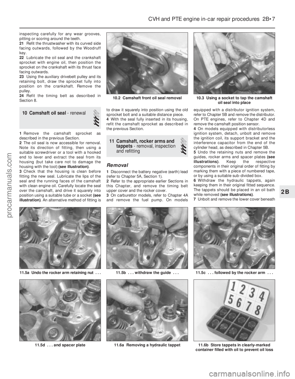
2 The oil seal is now accessible for removal.
Note its direction of fitting, then using a
suitable screwdriver or a tool with a hooked
end to lever and extract the seal from its
housing (but take care not to damage the
housing with the tool) (see illustration).
3 Check that the housing is clean before
fitting the new seal. Lubricate the lips of the
seal and the running faces of the camshaft
with clean engine oil. Carefully locate the seal
over the camshaft, and drive it squarely into
position using a suitable tube or a socket (see
illustration) . An alternative method of fitting is to draw it squarely into position using the old
sprocket bolt and a suitable distance piece.
4
With the seal fully inserted in its housing,
refit the camshaft sprocket as described in
the previous Section.
11 Camshaft, rocker arms and tappets - removal, inspection
and refitting
3
Removal
1 Disconnect the battery negative (earth) lead
(refer to Chapter 5A, Section 1).
2 Refer to the appropriate earlier Sections in
this Chapter, and remove the timing belt
upper cover and the rocker cover.
3 On carburettor models, refer to Chapter 4A
and remove the fuel pump. On models equipped with a distributor ignition system,
refer to Chapter 5B and remove the distributor.
On PTE engines, refer to Chapter 4D and
remove the camshaft position sensor.
4
On models equipped with distributorless
ignition system, detach, unbolt and remove
the ignition coil, its support bracket and the
interference capacitor from the end of the
cylinder head, as described in Chapter 5B.
5 Undo the retaining nuts and remove the
guides, rocker arms and spacer plates (see
illustrations) . Keep the respective
components in their original order of fitting by
marking them with a piece of numbered tape,
or by using a suitable sub-divided box.
6 Withdraw the hydraulic tappets, again
keeping them in their original fitted sequence.
The tappets should be placed in an oil bath
while removed (see illustrations) .
7 Unbolt and remove the lower cover beneath
CVH and PTE engine in-car repair procedures 2B•7
11.5a Undo the rocker arm retaining nut . . .
10.3 Using a socket to tap the camshaft
oil seal into place
11.6b Store tappets in clearly-marked
container filled with oil to prevent oil loss11.6a Removing a hydraulic tappet
11.5c . . . followed by the rocker arm . . .11.5b . . . withdraw the guide . . .
11.5d . . . and spacer plate
10.2 Camshaft front oil seal removal
2B
1595Ford Fiesta Remakeprocarmanuals.com
http://vnx.su