1988 PONTIAC FIERO brake fluid
[x] Cancel search: brake fluidPage 1433 of 1825
DRIVER INFORMATION CENTER (DDC) I $
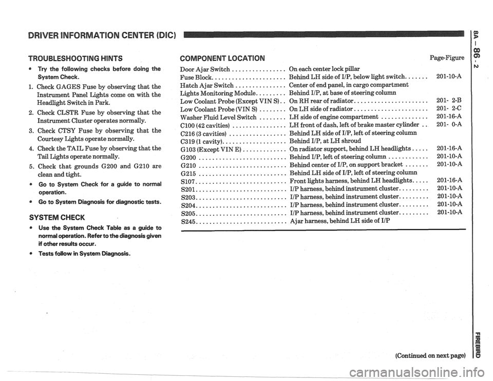
TROUBLESHOOTING HINTS
@ Try the following checks before doing the
System Check.
1. Check GAGES Fuse by observing that the
Instrument Panel Lights come on with the
Headlight Switch in Park.
2. Check CLSTR Fuse by observing that the
Instrument Cluster operates
normally.
3. Cheek CTSU Fuse by observing that the
Courtesy Lights operate normally.
4. Check the TAIL Fuse by observing that the
Tail Lights operate normally.
5. Check that grounds 6200 and 6210 are
clean and tight.
@ Go to System Check for a guide to norrnal
operation.
@ Go to System Diagnosis for diagnostic tests.
SYSTEM CHECK
@ Use the System Check Table as a guide to
normal operation. Refer to the diagnosis given
if other results occur.
Tests follow in System Diagnosis.
COMPONENT LOCATION Page-Figure
Door Ajar Switch
................ On each center lock pillar
..................... Fuse Block.
Behind LH side of IIP, below light switch. ...... 201-10-A
Hatch Ajar Switch
............... Center of end panel, in cargo compartment
Lights Monitoring Module.
........ Behind IIP, at base of steering column
..................... Low Coolant Probe (Except VIN S) .. On RR rear of radiator. 201- 2-B
..................... Low Coolant Probe (VIN S) ........ On LR side of radiator. 201- 2-C
.............. Washer Fluid Level Switch ........ LN side of engine compartment 201-16-A
................ el00 (42
cavities) LN
front of dash, left of brake master cylinder .. 201- 0-A
................. 6216 (3 cavities) Behind LN side
of IIP, left of steering column
.................. C319 (1 cavity). Behind I/P, at
LN shroud
............. 6103 (Except VIN E) On radiator support, behind LH headlights. .... 201-16-A
.......................... ............ 6200 Behind IIP, left of steering column 201-10-A
.......................... 6210 Behind center of IIP, on support bracket ....... 201-10-A
.......................... 6215 Behind
LH side of IIP, left of steering column
.......................... .... S107. Front lights harness, behind LN headlights. 201-16-A
.......................... S201. IIP harness, behind instrument cluster. ........ 201-10-A
.......................... S203. I/P harness, behind instrument cluster. ........ 201-10-A
.......................... S204. I/P harness, behind instrument cluster. ........ 201-10-A
.......................... S205. I/P harness, behind instrument cluster. ........ 201-10-A
.......................... S245. Ajar harness, behind LN side of IIP
(Continued on next page)
Page 1440 of 1825
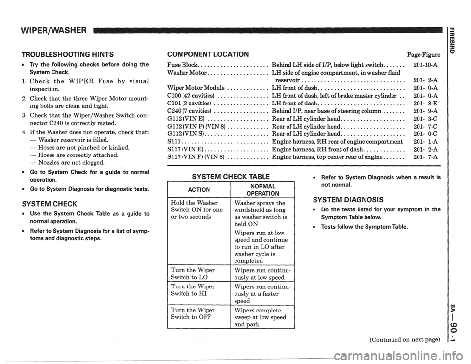
TROUBLESHOOTING HINTS
0 Try the following checks before doing the
System Check.
1. Check the WIPER Fuse by visual
inspection.
2. Check that the three Wiper Motor mount-
ing bolts are clean and tight.
3. Check that the Wiper/Washer Switch con-
nector C240 is correctly mated.
4. If the Washer does not operate, check that:
- Washer reservoir is filled.
- Hoses are not pinched or kinked.
- Hoses are correctly attached.
- Nozzles are not clogged.
r Go to System Check for a guide to, normal
operation.
0 Go to System Diagnosis for diagnostic tests.
SYSTEM C H EGK
Use the System Check Table as a guide to
normal operation.
Refer to System Diagnosis for a list of symp-
toms and diagnostic steps.
COMPONENT LOCATION Page-Figure
...... ..................... Fuse Block. Behind LH side of IIP, below light switch.
Washer Motor.
.................. LH side of engine compartment, in washer fluid
reservoir
................................
.......................... Wiper Motor Module ............. LH front of dash.
.. Cl00 (42 cavities) ................ LH front of dash, left of brake master cylinder
.......................... C101 (3 cavities) ................. LH front of dash.
....... C240 (7 cavities) ................. Behind IIP, near base of steering column
................... 6112 (VIN E) ................... Rear of LH cylinder head.
................... 6112 (VIN F) (VIN 8) ............. Rear of LH cylinder head.
................... 6112 (VIN S) .................... Rear of LW cylinder head.
Slll ........................... Engine harness, RH rear of engine compartment
............ S117 (VIN E) .................... Engine harness, RH front of dash.
...... S117 (VIN F) (VIN 8) ............. Engine harness, top center rear of engine.
SYSTEM CHECK TABLE Refer to System Diagnosis when a result is
not normal.
SYSTEM DIAGNOSIS
0 Do the tests listed for your symptom in the
Symptom Table below.
0 Tests follow the Symptom Table.
or two seconds
Wipers run at low
(Continued on next page)
. __- ______ --___ -..- .
Page 1444 of 1825
WIPERIWASHER: PULSE, CD4 I G n
TROUBLESHOOTING HINTS
Try the following checks before doing the
System Diagnosis.
1. Check the Wiper Fuse by visual inspection.
2. Check that the three
VViper Motor mounting
bolts are clean and tight.
3. Check that Wipermasher Switch connector
C240 and WiperIWasher Motor Module Con-
nectors are mated correctly.
4. If the Washer does not operate, check that:
- The Washer reservoir is filled.
- The hoses are not pinched or kinked.
- The hoses are correctly attached.
- The nozzles are not clogged.
Go to System Check for a guide to normal
operation.
Go to System diagnosis for diagnostic tests.
SYSTEM CHECK
Use the System Check Table as a guide to
normal operation.
e Refer to System diagnosis for a list of symp-
toms and diagnostic steps.
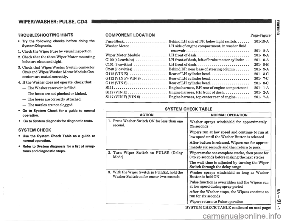
COMPONENT LOCATION Page-Figure
...... ..................... Fuse Block. Behind LR side of IIP, below light switch.
.................. Washer Motor. LH side of engine compartment, in washer fluid
reservoir
................................
.......................... ............. Wiper Motor Module LN front of dash.
.. C100 (42 cavities) ................ LR front of dash, left of brake master cylinder
.......................... C101(3 cavities) ................. LH front of dash.
....... C240 (7 cavities) ................. Behind IIP, near base of steering column
................... 6112 (VIN E) ................... Rear of LN cylinder head.
................... 6112 (VIN F) (VIN 8) ............. Rear of LN cylinder head.
................... 6112 (VIN S) .................... Rear of LH cylinder head.
S111 ........................... Engine harness, RN rear of engine compartment
............ S117 (VINE) .................... Engine harness, RN front of dash.
...... S117 (VIN F) (VIN 8) ............. Engine harness, top center rear of engine.
SYSTEM CHECK TABLE
Wipers run at low speed and continue to run at
low speed until the Washer Button is released
Pulse function is overridden and the Wipers
run
After the Washer stops, the Wipers continue to
run for six seconds
I Wipers return to Pulse operation
(SYSTEM
CHECK TABLE continued on next page)
Page 1520 of 1825
HATCH RELEASE P
E
TROUBLESHOOTING H lNTS
0 Try the following checks before doing the
System Diagnosis.
1. Check the CTSY Fuse by operating the
Radio.
2. Check that the Hatch Release Solenoid
case ground is clean and tight.
3. Check the Parking Brake Switch by apply-
ing Parking Brake with Ignition Switch in
RUN and observing the BRAKE Indicator.
@ Go to System Check for a guide to normal
operation.
Go to System Diagnosis for diagnostic tests.
SYSTEM CHECK -
o Use the System Check fable as a guide to
normal operation.
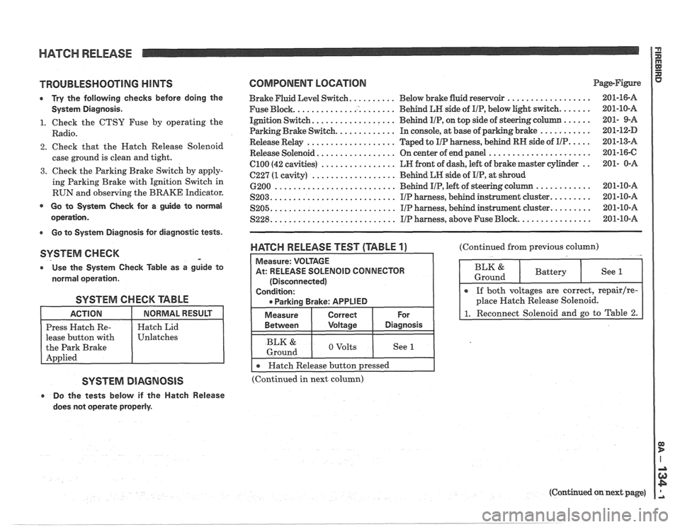
SYSTEM CHECK TABLE
lease button with
SYSTEM DIAGNOSIS
e Do the tests below if the Hatch Release
does not operate properly.
COMPONENT LOCATION Page-Figure
Brake Fluid Level Switch. ......... Below brake fluid reservoir ..................
Fuse Block. ..................... Behind LN side of IIP, below light switch. ......
Ignition Switch. ................. Behind IIP, on top side of steering column ......
Parking Brake Switch. ............ In console, at base of parking brake ...........
Release Relay ................... Taped to IIP harness, behind RN side of IIP. ....
Release Solenoid ................. On center of end panel ......................
el00 (42 cavities) ................ LN front of dash, left of brake master cylinder ..
C227 (1 cavity) .................. Behind LN side of IIP, at shroud
6200
.......................... Behind IIP, left of steering c
S203. .......................... IIP harness, behind instrunnent cluster. ........
.......................... ........ S205. IIP harness, behind instrument cluster.
S228. .......................... IIP harness, above Fuse Block. ...............
WATGH RELEASE TEST (TABLE 1)
At: RELEASE SOLENOID CONNECTOR
(Disconnected)
I 0 Parkina Brake: APPLIED I
I Measure I Correct I For
(Continued from previous column)
BLK & 1 o volts I See I 1 Ground
I r Hatch Release button pressed I --
(Continued in next column)
(Continued on next page)
Page 1577 of 1825
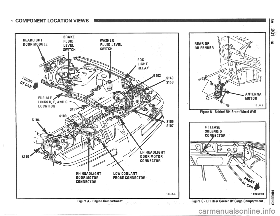
COMPONENT LOCATION VlEWS I E!
BRAKE
HEADLIGHT FLUID
DOOR MODULE - LEVEL
WASHER
FLUID LEVEL
RN HEADLIGHT LOW COOLANT
DOOR MOTOR PROBE CONNECTOR
CONNECTOR
12H3.4
Figure B - Behind RN Front Wheel Well
RELEASE
SOLENOlD
CONNECTOR
Figure C
- LH Rear Corner Of Cargo Compartment
Page 1817 of 1825
2 - CHASSIS INDEX
Backup Lamp Switch (Circuit) .......... 8A- 1 12. 7A 1-5
Backup Lights
..................................................... 8B-1
...................................................... Battery Section 6D 1
............................ Battery Specification Chart 6D 1-7
.................................... Body Identification ... .... OA- 1
Borg Warner Rear Axle .......................... Section 4B1
...................................................... Blower Motor 1A-14
Blower Switch
.................................................... 1 A- 13
Booster Assembly
............................................. 5D2-2
Brakes
- General ......................................... Section 5
Adjustment
.................................................... 5C3-4
Booster Assembly
. Tandem
Diaphragm
................... .... ..................... 5D2- 1
................................................ Components 5C3- 1
Diagnosis and Inspection
................................. 5-3
Disc Brake Caliper Assembly
.................................................... 3548 Series 5B6-1
Drum Brake Assembly ........................ Section 5C3
General Description
.......................................... 5-2
On-Car Service
.................................................... 5-7
Specifications & Special Tools ......................... .5 F. 1
...................................................... Unit Repair 5A3- 1
.......................................... Warning System 8A-4 1-0
............ Brake Pedal Mounting .. ......................... 5-1 7
Bulb Usage Chart
............................................ 8B-10
............................................ Bumpers Section 2B,3 D.6
Bumper Energy Absorbing Units
.................... 2B-2
Bench Testing
................................................ 2B-3
........................................ Damage/Leakage 2B-3
................................ Removal After Collision 2B-2
............................................. Fascia Rub Strips .2 B. 1
.................................................... Front Bumper 2B-2
Assembly
........................................................ 2B-4
Energy Absorber
........................................... 2B-4
............................................................. Fascia .2 B. 1
On-Vehicle Service
...................................... 2B-4
Rear Bumper
.................................... .... ............ 2B-2
........................................................ Assembly 2B-5
Energy Absorber
............................................ 2B-4
............. .................... Fascia Molding Strip .. 2B-5 ........................................... Service Procedures .2 B. 1
.................................................. Specifications 2B-5
C
Caliper Assembly . Disc Brake
.............................................. 3000/3 100 Series 5B 1-2
3548 Series
...................................................... 5B6-2
Caliper Overhaul
....................... 3000/3 100 Series .. ............... 5B 1-4
3548 Series
.................................................... 5B6-5
Caster and Camber Adjustment
........................ 3A- 1
............................................. Catalytic Converter 6F-2
Center High-Mounted Stoplight
....................... ... 8B- 1
Charging System
...................... 8A.30.7, Section 6D3
Chassis Electrical
.................................... Section 8B
Center High Mounted Stoplight
...................... 8B-1 ................................. Exterior Light Monitor .8 B. 1
................................................................ Chimes 8A-77
................................ Cigar Lighter (Circuit) 8A- 1
14-0
.............................. Circuit Breaker Details Section 8A
Power ACC Circuit Breaker .... 8A- 10.1.10.3.10.5.
11-3
.... Window Circuit Breaker 8A~10~1,10~3.10~5.1 1.4
Clutch
........................................................ Section 7C
......................................... General Description .7 C. 1 ........................................................... Diagnosis 7C-2 Bleeding
Hydraulic Clutch System
................. .7 C.2
Preliminary Checks ..................................... ... 7C-2
On-Vehicle Service
........................................... 7C-5
Clutch Hydraulic System
.................................. 7C-5
Clutch Pedal ...................................................... 7C-6
Pilot Bearing
..................................................... 7C-6
Pressure Plate and Disc
.................................... 7C-6
Special Tools
......................... ....... ................ 7C-8
Specifications
................................................... 7C-8
Coil Springs and Insulators .............................. 3D-1
Component Fluid Capacities
................................ OB-6
Component Location Views
........................ 8A-201-0
Composite Master Cylinder
................... Section 5A3
Compression Test
.................. .. ............................. 6-5
Condenser Mounting
....................................... 1B 1-24
Connectors
.................................................... 8A-202-0
Coolant Fan Temperature Switch
...................... 8A-3 1
Cooling and Radiator
................................ Section 6B
Cooling System Capacities
................................. OB-6
Cooling System Diagnosis
.................................... 6B-3
Cranking System
...................................... Section 6P*
Diagnosis ..................................................... 6~2
General Description ................................ 6D2- 1
Cranking System
........................................ 6D2- 1
Solenoid
................................................... 6D2- 1
Starter Motor ......................................... 6D2-1
On-Vehcile Service
...................................... 6D2-4
Specifications
............................................ 6D2- 1
Starter
........................................................ 6D2-4
Unit Repair
............................................ 6D2-6- 11
Service Procedures
...................................... 6D2-3
Cruise Control
.............................. 8A-34-0, Section 9B
Diagnosis
............................................................ 9B-4
Cruise Set Speed High or Low
.................... 9B-4
Cruise System Surges
.................................. 9B-4
Cruise Tap-Up and Tap-Down
...................... 9B-4
Excessive Cruise Speed Loss on
Hills
........................................................... 9B-4
General Description
........................................ 9B-1
Electrical and Vacuum Release
Switches
...................................................... 9B-4
Electrical Harness
.......................................... 9B-A
Electronic Controller (Module) .................... 9B .
Off/On/Resume/Accel Switch
Operation
.................................................. .91 B-
Servo Unit
.................................................... 9B-2
Set/Coast Button Switch .............................. 9B-1
................................................ Speed Sensors 9B-3
Vacuum Supply
............................................ 9B-4
On-Car Service
.................................................. 9B-6
................................ Cruise Release Switches 9B-6
.......................................... Servo Mounting 9B-10
Vacuum Harness and Cable Routing
VIN
E ................................. .. .................. 9B,7
.................................................... VIN F, 8 9B-9
....................................................... VIN S 9B-8
........................ Vacuum Tank - VIN S,F,E, 9B-10
.............................. Cruise Control (Circuit) 8A-34-0
D
......................................... Defogger (Circuit) $A-6 1-0
..................... ...... Defroster Duct Assembly ... .812 C-
Diagnosis
Air Conditioning
- General ........................... 1B-5
.................... Automatic Transmission - General 7A
Automatic Transmission
- ................ HD-700-R4-2
Page 1823 of 1825
8- CHASSIS INDEX
Recommended Fluids and Lubricants ................ OB-6
Relay Rod
......................................................... 3B6-2
Remote Mirror Control
...... See Body Service Section
5H.1. 15
Repair Procedures
.......................................... 88-50
S
........................................ Scheduled Maintenance OB- 1
Seats (Power) ....................................... Lumbar Support 8A- 145-0
............................. Sequential Fuel Injection 6E3-C2- 1
Service Engine Soon Light
.................................... 8C-3
Sheet Metal and Grille
................................ Section 2C
......................................... General Description .2 C. 1
........................................... Service Procedures .2 C. 1
................................................................. Hood .2 C. 1
...................................................... Hood Hinge 2C-2
Hood Latch and Cable
...................................... 2C-2
Paint
.............................................. Color Matching 2C-5
................................................ Identification -32-6
Interior Plastic Parts ...................................... 2C-6
................................................ Shock Absorbers 3D-
1
Shoe and Lining Assembly
. Brake
............................................ 3000/3 100 Series 5B1-3
3548 Series ...................................................... 5B6-4
Side Marker Lights
.............................................. 8B-2
........ Speakers See 8A- 150-0 & Body
Manual Section
6H- 1
.................... Spark Plug Gap .. .................. 6E3-13-3
................................ Speaker and Speaker Grille 9A-9
Special Tools
............................................ Air Conditioning 1 B-3 5
Air Conditioning Compressor
................................................. Overhaul 1D1-21
........................ Automatic Transaxle AT-700-R4-64
................................................................ Brakes SF-1
Clutch ................................................................ 7C-8
................................................................ Rear 4B1-20
....................................... Rear (Borg Warner) 4B-20
........................... Driveability and Emissions .6 E. 17
................................................ Engine Cooling 6B- 14
Power Steering Pump
& Gear ...................... 3B7-17
............................................... Propeller Shaft .4 A. 12
Steering Wheels and Columns
.......................... 5-35
Specifications Automatic Transmission Unit
............................................ Repair AT-700-R4-59
..................................................... Battery 6D 1-7
................................................................ Brakes 5F-1
Bumpers
......................................................... 2B-5
Charging System
................ .. ................... 6D3-3
.............................................................. Clutch .7 (2.8
....................................... Cranking System 6D2- 1 1
Driveability and Emissions ............................ 6E-23
................................................ Engine (V-6) ..6A 2.26
Engine (V-8) .................................................. 683-28
........................................ Front Suspension 3C- 10
Power Steering Gear and Pump
.................. 3B7-18 ............................................. Propeller Shaft .4 A. 12 ........................................................ Rear Axle 4B-19 ............................ Rear Axle (Borg Warner) 4B 1- 19
Rear Suspension
.............................................. 3D-9
.......................................... Replacement Bulbs 8Br 10 .............................................. Steering Linkage 3B6-6
Steering Wheels and Columns
...................... 3B5-35
........................................ Wheel Alignments 3A-4
....................................................... Speedometer 8C-2
........................................ Speedometer (Removal) 8C-5
...................................................... Speed Sensors 8C-1
Starter ........................................ Section 6D2. 8A-30-0
............................................. Starter (Circuit) 8A-30-0
Steering Linkage ...................................... Section 3B6
....................................... General Description 3B6-1
........................ Maintenance and Adjustments 3B6-1
................................................ On-Car Service 3B6-2
..................................................... Idler Arm 3B6-4
................................................ Pitman Arm 3B6-5
.................................................... Relay Rod 3B6-3
Tie Rods
...................................................... 3B6-2
.................................................. Specifications 3B6-6
Steering, Suspension, Tires and
Wheels Diagnosis
............................................................. 3-1
Steering Wheels and Columns
............................ 3B5-1
..................................... General Information 3B5- 1
Maintenance and Adjustments
...................... 3B5-'
On-Car Service .............................. .. ........... 3B5
Checking for Accident Damage
.................. 3B5-5
Intermediate Shaft ............... .. .................... 3B5-3
Park Lock Cable .......................................... 3B5-4
Standard Column
............................. Automatic Transaxle 3B5-13
Manual Transaxle ................................. 3B5- 19
Tilt Column
.............................. Automatic Transaxle 3B5-27
.................................. Manual Transaxle 3B5-19
Unit Repair Intermediate Shaft
...................................................... Assembly 3B5-6
................................................. Special Tools 3B5-35
Torque Specifications
.................................... 3B5-35
............................................. Starting System 8A-30-0
........................................ Strut Assembly (Front) 3C-4
.................................... ..... Symbols Chart ... 8A-3-0
T
.......................................................... Tachometer 9G-1
Tail/Stop/Turn Signal/Lights .......................... 8B-2
Temperature Cable
.............................................. 112 A-
Temperature Warning Light ................................ 8C-3
Theft Deterrent (Circuit)
.............................. 8A-133-0
Tie Rods
.............................................................. 3B6-2
Tires and Wheels
........................................ Section 3E
Diagnosis
.................................................. Section 3
General Information
......................................... 3E-1
................................................... Metric Tires 3E-2
....................................... Replacement Tires .31 E-
.................................................... Tire Placard 3E-2
........................................................... Wheels 3E-2
Maintenance and Adjustments
.......................... 3E-2
.......................... Aluminum Wheel Cleaning 3E-9
............................. ......... Inflation of Tires .. 3E-3
........................................ Tire Chain Usage 3E-4
.................................................. Tire Rotation 3E-3
.............................................. Wheel Repair 3E-2
...................................... Wheel Studs/Nuts 3E-3
........................................... Service Operations 3E-4
........................ Aluminum Wheel Cleaning 3E-9
.................................... Balance Precautions 3E-7
............................ Balancing Tire and Wheel 3E-7
.............................................. Compact Spare 3E-6
........................ Correcting Nonuniform Tires 3E-8