1988 PONTIAC FIERO air condition
[x] Cancel search: air conditionPage 99 of 1825
101.20 R-4 AIR CONDITIONING COMPRESSOR OVERHAUL
suction and/or discharge valves leaking, an
internal leak or an inoperative valve, and the
compressor should be disassembled and checked
for cause of leak. Repair as needed, reassemble
and repeat the pump-up test. Externally leak test.
When the pressure pump-up test is completed,
release the air pressure from the HIGH side and
remove the Gage Adapters J-5420 and Test Plate
J-9625-A. 18. On the R-4 compressor, tilt the compressor so
that the compressor suction and discharge ports
are down. Drain the oil from the compressor.
19. Allow the compressor to drain for
10 minutes,
then charge with the proper amount of oil. The
oil may be poured into the suction port.
If further assembly or processing is required, a
shipping plate or Test Plate J-9625-A should be
installed to keep out air, dirt and moisture until
the compressor is installed.
Page 100 of 1825
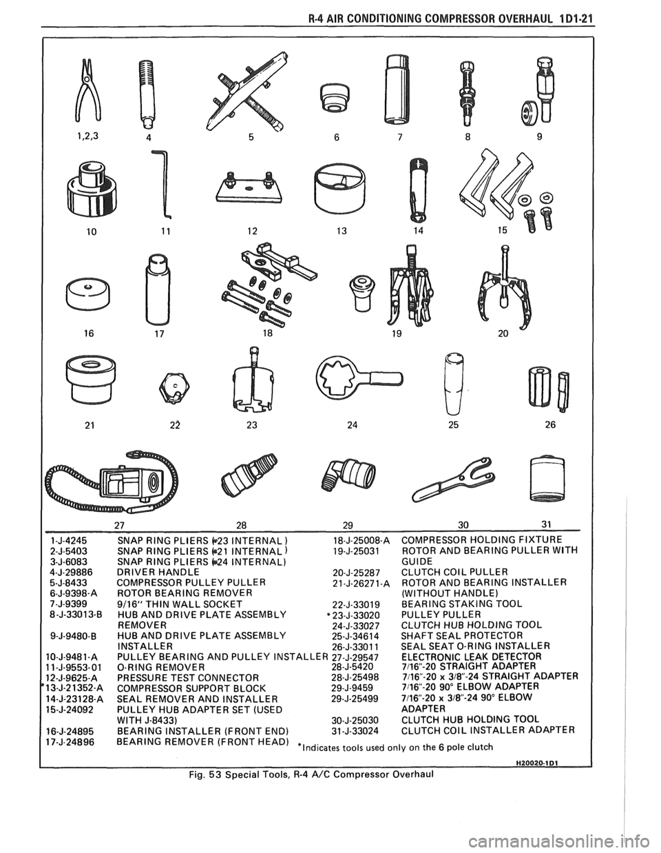
R-4 AIR CONDITIONING COMPRESSOR OVERHAUL 1 Dl-21
SNAP RING PLIERS b23 INTERNAL ) 18-J-25008-A COMPRESSOR HOLDING FIXTURE
SNAP
RING PLIERS @21 INTERNAL) 19-J-25031 ROTOR
AND BEARING PULLER WITH SNAP RING PLIERS 44424 INTERNAL)
GUIDE
DRIVER HANDLE 20-J-25287 CLUTCH COIL PULLER
COMPRESSOR PULLEY PULLER 21-J-26271.A ROTOR AND BEARING INSTALLER
ROTOR BEARING REMOVER (WITHOUT HANDLE)
9/16"
THIN WALL SOCKET
22-J-33019 BEARING STAKING TOOL
HUB AND DRIVE PLATE ASSEMBLY "23-J-33020 PULLEY PULLER
REMOVER 24-J-33027 CLUTCH HUB HOLDING TOQL
HUB AND DRIVE PLATE ASSEMBLY 25-J-34614 SHAFT SEAL PROTECTOR
INSTALLER 26-J-33011 SEAL SEAT O-RING INSTALLER
PULLEY BEARING AND PULLEY INSTALLER
27-J-29547 ELECTRONIC LEAK DETECTOR
O-RING REMOVER 28-J-5420 7116"-20 STRAIGHT ADAPTER
PRESSURE TEST CONNECTOR 28-J-25498 7116"-20 x 3/8-24 STRAIGHT ADAPTER
COMPRESSOR SUPPORT BLOCK 29-J-9459 7116"-20 90" ELBOW ADAPTER
SEAL REMOVER AND INSTALLER 29-J-25499 7/16-20 x 318"-24 90" ELBOW
PULLEY HUB ADAPTER SET (USED ADAPTER
WITH
J-8433) 30-J-25030 CLUTCH HUB HOLDING TOOL
BEARING INSTALLER (FRONT END) 31-J-33024 CLUTCH COIL INSTALLER ADAPTER
HEAD) "Indicates tools used only on the 6 pole clutch
Fig.
53 Special Tools, R-4 A/C Compressor Overhaul
Page 110 of 1825
CHASSIS SHEET METAL 2C-3
3. Allow hood to open, and tighten latch bolts in
new location.
FENDER PANEL
An outer fender panel with a plastic inner panel
is used. Care should be used in handling raw fenders
due to the lack of fender rigidity prior to installation.
Body surfaces at molding areas must be cleaned
thoroughly with suitable organic solvent immediately
prior to installation to ensure adhesion. Do not allow
adhesive surface of molding to come in contact with
wet solvent, dirt, or foreign matter.
NO"FICE: If heat source is used to condition
moldings prior to installation, the source is to
provide
uniform heating, not to exceed 85°F.
Application is to be made in a clean area with
ambient and body surface temperatures of at least
65°F.
The moldings are to be secured with two appli-
cations of a force of 20 pounds for the full length of
each section using a roller or other suitable tool.
Any section of molding removed once in contact
with the body surface must be replaced.
ALUMINUM PANEL REPAIR PROCEDURES
An aluminum hood (inner and outer panel) is
used on some vehicles. An aluminum panel can be
identified by checking it with a magnet, preferably in
the front corners to avoid any possible damage to the
paint. Aluminum will not attract a magnet.
Aluminum panels can be repaired successfully
with only slight changes of materials and techniques
commonly used to refinish steel panels. The necessary
modifications fall into two categories: 1) metal
preparation; and 2) painting.
Metal Preparation
1. Because aluminum is relatively easy to grind,
care must be taken not to use overly coarse abra-
sive discs or excessive grinder speeds (greater
than 2,000 rpm), both of which will cause
excessive heat and unnecessary metal removal.
2. Surface scratches should normally be removed
with 180 or 120 grit paper with scalloped edges.
Hand sanding with 80 grit paper will usually be
sufficient to remove excessive body filler or
heavy scratches, again followed with 180 grit
paper.
NOTICE: Avoid scratching aluminum when
sanding with 80 grit paper by hand.
3. Foam backed pads are recommended for
grinders used on aluminum, rather than the
stiffer rubber pads used for mounting abrasive
discs used on steel. The foam pad helps to
reduce heat build-up and improves blending for
feathering.
4. Localized heat, generated by grinding, can be
minimized by the use of a grease stick, such as
Formax F-160 or equivalent. This does, how-
ever, tend to load up the grinding discs quickly,
which should be periodically cleaned by rotating
them against a brush wetted with solvent.
5. If out-dings or minor convex defects need to be
filed, it is recommended to use a round edge,
double cut, flexible file with 22 teeth per inch
overlaid with 52 teeth per inch (such as
Nicholson
#50-412 or equivalent).
NOTICE: Keep file clean so that chips do not
scratch aluminum.
The use of heat is not recommended, since the
structural characteristics of aluminum are noticeably
affected by heat. A bent or buckled aluminum hood,
which exhibits strain cracks either before or after
straightening, should be replaced.
Both steel and aluminum panels can be metal
prepped and repaired with two-part polyester filler
materials in the same number of operations. The only
differences are that less aggressive type files and abra- sive discs should be used, with care being taken not to
overheat the aluminum.
Painting
Painting procedures for aluminum panels differ
very little from those used on steel panels. Two pre-
cautions should, however, be observed:
1. Alkaline base paint removers are not recom-
mended and should not be used.
2. Aluminum also requires a chemical cleaner such
as
DuPont 2253, Ditzler DX-533, or equivalent
be used on bare metal to remove contaminants
and corrosion. After cleaning, a conversion
coating such as DuPont
226S, Ditzler DX-503
or equivalent should be applied to promote
adhesion.
Beyond these considerations, painting alumi-
num panels should present no increases in difficulty or
changes in procedure and technique.
PAINTING AND REPAIRING NONMETAL
EXTERIOR PARTS 1
FiberglassIABS Plastic Panel Repair ~
A Plastic Solder Repair Kit can be used to repair
cracks, dents, or pits in fiberglass or ABS panels. A
Glass Woven Cloth should be installed on the under
side of a crack in the panel to structurally reinforce the
panel. The following procedure can be used to repair
the panels:
1. With a lacquer removing solvent, remove paint
from damaged area down to the fiberglass or
, ABS material. I
2. Scuff-sand area surrounding damaged area to
provide a good bonding surface.
Page 128 of 1825
STEERING, SUSPENSION, VIBES AND WHEELS DIAGNOSIS 3-3
Steering Wheel Kick-Back (Power)
Inspect
e Air in system
e Loose steering gear mounting
e Joints from column to steering gear loose or worn
e Tie rod ends loose
Worn or missing check valve
(800 series)
e Wheel bearings worn
e See "Too Much Play In Steering" for other
possible causes.
Steering Wheel Surges Or Jerks (Power)
Inspect
Hydraulic system - Make pressure test with gage
J 5176-D or
J 25323
e Sluggish steering gear valve
Loose pump drive belt
Cupped Tires
Inspect
Front-wheel or rear-wheel alignment
e Strut dampeners or shock absorbers weak
e Wheel bearing worn
e Excessive tire or wheel runout
e Worn ball joint
a Loose steering gear adjustment
POWER RECIRCULATING BALL
SEERING GEAR DIAGNOSIS
Hissing Noise
There is some noise in all power steering systems.
One of the most common is a hissing sound when the
steering wheel is turned and the car is not moving. This
noise will be most evident when turning the wheel
while the brakes are applied. There is no relationship
between this noise and steering performance. Do not
replace the valve unless the "hissing" noise is extremely
objectionable. A replacement valve will also have a
slight noise, and is not always a cure for the condition.
Check that the intermediate shaft joints are not loose.
Rattle or Chucking Noise
Inspect -
Pressure hose grounding out
e Tie rod ends loose
e Steering gear attachment loose
a Loose pitman shaft "over-center" adjustment.
A slight rattle may occur on turns because of
increased clearance off the "high point". This is
normal and clearance must not be reduced below
specified limits to eliminate this slight rattle.
Poor Return of Steering Wheel to Center
Front-wheel alignment
Wheel bearing worn
Tie rod end binding
Ball joint binding
Steering wheel rubbing against turn signal
housing
Steering gear adjustments
Tight or frozen intermediate steering shaft
Sticky or plugged spool valve
Momentary Increase in Effort Whsn Turning
Wheel Fast to Right or Left
Inspect
High internal leakage
Steering Wheel Surges or Jerks When Turning
With
Engine Running Especially During Parking
ln8pe~t
e Insufficient pump pressure
Sticky flow control valve
Excessive Wheel Kickback or Loose Steering
Air in system
Steering gear attachment loose
Tie rod ends loose
Wheel bearings worn
Steering gear flexible coupling loose on shaft or
rubber disc mounting nuts loose
Loose thrust bearing preload adjustment
Excessive "over-center" lash
Worn pressure port check valve
Hard Steering or Lack of Assist
(Especially During Parking)
-
Brakes applied while turning steering wheel
Intermediate shaft damaged or worn
e Sticky flow control valve
Insufficient pump pressure
Excessive internal pump leakage
Excessive internal steering gear leakage
STEERING LINKAGE DIAGNOSIS
Excessive Play or Looseness in Steering Systern
inspect
r, Worn upper ball joints
e Steering gear worm bearings loosely adjusted
Page 135 of 1825

3-10 STEERING, SUSPENSION, TIRES AND WHEELS DIAGNOSIS
Reminder Keeps Operating With Key In Lock
Cylinder, Driver's Door Open Or Closed; Ceases
When Key Is Removed
Inspect
s Door jamb switch on driver's side misadjusted or
inoperative.
e Wire from signal switch to door jamb switch
shorted.
A. This condition indicates the lock cylinder or
the reminder switch is at fault. To verify,
check for continuity at the
"E" and "F"
male column connector contacts, with the
key removed from the lock cylinder. If
continuity exists, the fault is in the column.
B. Insert the key into the lock, then turn the
lock toward the "Start" position. If the
reminder stops when the key is in the
"Run" position or when it is turned past
"Run" toward "Start," the problem is a
sticky lock cylinder actuator.
COLUMN-MOUNTED DIMMER SWITCH
No "Low" or "High" Beam
Inspect
e Loose connector at dimmer switch
e Improper adjustment
e Internally damaged or worn switch. Check the
continuity on the switch at the It. green and at the
tan switch terminals by pushing in the plunger all
the way.
A click should be heard. If there is no
continuity, replace the dimmer switch. If there is
continuity, refer
to'section 8A for electricaldiag-
nosis.
PIVOT AND SWITCH ASSEMBLY
Switch Inoperative: No "Low," "High" and/or
"Wash"
e Loose body-to-switch connector
a Broken or damaged switch
Internally damaged or worn switch. Connect a
new switch without removing the old one. If the
system functions, replace the switch. If the
system doesn't function, refer to Section
8A for
electrical diagnosis.
STEERING GEAR AND PUMP LEAKS
General Procedure
Inspect
s Overfilled reservoir
s Fluid aeration and overflow
e , Hose connections
Verify exact point of leakage Example:
Torsion bar, stub shaft and
adjuster seals are close together; the exact
spot where the system is leaking may not be
clear.
Example: The point from which the fluid is
dripping is not necessarily the point where
the system is leaking; fluid overflowing from
the reservoir, for instance.
e When service is required:
A. Clean leakage area upon disassembly.
B. Replace leaking seal.
C. Check component sealing surfaces for
damage.
D. Reset bolt torque to specifications, where
required.
Some complaints about the power steering system
may be reported as:
A. Fluid leakage on garage floor
B. Fluid leaks visible on steering gear or pump
C. Growling noise, especially when parking or
when engine is cold
D. Loss of power steering when parking
E. Heavy steering effort
When troubleshooting these kinds of complaints,
check for an external leak in the power steering system.
For further diagnosis of leaks, refer to External
Leakage Check in this section.
External Leakage Check
Fig. 12
The purpose of this procedure is to pinpoint the
location of the leak.
In some cases, the leak can easily be located. But,
seepage-type leaks may be more difficult to isolate. To
locate seepage leaks, use the following method.
1. With the engine off, wipe dry the complete power
steering system.
2. Check the fluid level in the pump's reservoir. Add
fluid if necessary.
3. Start the engine, then turn the steering wheel
from stop to stop several times. Do not hold it at
a stop for any length of time, as this can damage
the power steering pump. It is easier if someone
else operates the steering wheel while you search
for the seepage.
4. Find the exact area of the leak and repair leak.
SEAL REPLACEMENT
RECOMMENDATIONS
Lip seals, which seal rotating shafts, require
special treatment. This type of seal is used on the
steering gear and on the drive shaft of the pump. When
there is a leak in one of these areas, always replace the
seal(s), after inspecting and thoroughly cleaning the
sealing surfaces. Replace the shaft only if very severe
pitting is found. If the corrosion in the lip seal contact
zone is slight, clean the surface of the shaft with crocus
cloth. Replace the shaft only if the leakage cannot be
stopped by first smoothing with crocus cloth.
Page 137 of 1825
3-1 2 STEERING, SUSPENSION, TIRES AND WHEELS DIAGNOSIS
POWER STEERlNG SYSTEM "TEST
PROCEDURE
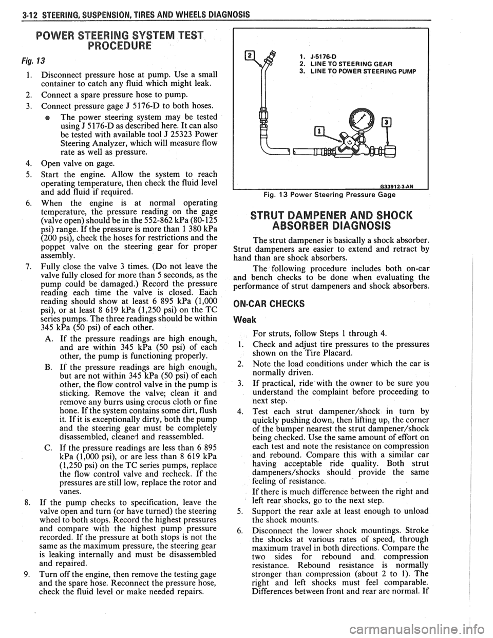
Fig. 13 1. J-5176-D 2. LlNE TO STEERING GEAR
1. Disconnect pressure hose at pump. Use a small 3. LINE TO POWER STEERING PUMP
container to catch any fluid which might leak.
2. Connect a spare pressure hose to pump.
3. Connect pressure gage
J 5176-D
to both hoses.
e The power steering system may be tested
using
J 5 176-D as described here. It can also
be tested with available tool
J 25323 Power
Steering Analyzer, which will measure flow
rate as well as pressure.
4. Open valve on gage.
5. Start the engine. Allow the system to reach
operating temperature, then check the fluid level
and add fluid if required.
6. When the engine is at normal operating
temperature, the pressure reading on the gage
(valve open) should be in the 552-862
kPa (80-125
psi) range. If the pressure is more than 1 380
kPa
(200 psi), check the hoses for restrictions and the
poppet valve on the steering gear for proper
assembly.
7. Fully close the valve 3 times. (Do not leave the
valve fully closed for more than 5 seconds, as the
pump could be damaged.) Record the pressure
reading each time the valve is closed. Each
reading should show at least 6 895
kPa (1,000
psi), or at least 8 619 kPa (1,250 psi) on the TC
series pumps. The three readings should be within
345
kPa (50 psi) of each other.
A. If the pressure readings are high enough,
and are within 345
kPa (50 psi) of each
other, the pump is functioning properly.
B. If the pressure readings are high enough,
but are not within 345
kPa (50 psi) of each
other, the flow control valve in the pump is
sticking. Remove the valve; clean it and
remove any burrs using crocus cloth or fine
hone. If the system contains some dirt, flush
it. If it is exceptionally dirty, both the pump
and the steering gear must be completely
disassembled, cleaned and reassembled.
C. If the pressure readings are less than
6 895
kPa (1,000 psi), or are less than 8 619 kPa
(1,250 psi) on the TC series pumps, replace
the flow control valve and recheck. If the
pressures are still low, replace the rotor and
vanes.
8. If the pump checks to specification, leave the
valve open and turn (or have turned) the steering
wheel to both stops. Record the highest pressures
and compare with the highest pump pressure
recorded. If the pressure at both stops is not the
same as the maximum pressure, the steering gear
is leaking internally and must be disassembled
and repaired.
9. Turn off the engine, then remove the testing gage
and the spare hose. Reconnect the pressure hose,
check the fluid level or make needed repairs.
Fig. 13 Power Steering Pressure Gage
STRUT DAMPENER AND SHOCK
ABSORBER DIAGNOSIS
The strut dampener is basically a shock absorber.
Strut dampeners are easier to extend and retract by
hand than are shock absorbers.
The following procedure includes both on-car
and bench checks to be done when evaluating the
performance of strut dampeners and shock absorbers.
ON-CAR CHECKS
Weak
For struts, follow Steps 1 through 4.
1. Check
and adjust tire pressures to the pressures
shown on the Tire Placard.
2. Note the load conditions under which the car is
normally driven.
3. If practical, ride with the owner to be sure you
understand the complaint before proceeding to
next step.
4. Test each strut
dampener/shock in turn by
quickly pushing down, then lifting up, the corner
of the bumper nearest the strut
dampener/shock
being checked. Use the same amount of effort on
each test and note the resistance on compression
and rebound. Compare this with a similar car
having acceptable ride quality. Both strut
dampeners/shocks should provide the same
feeling of resistance.
If there is much difference between the right and
left rear shocks, go to the next step.
5. Support the rear axle at least enough to unload
the shock mounts.
6. Disconnect the lower shock mountings. Stroke
the shocks at various rates of speed, through
maximum travel in both directions. Compare the
two sides for rebound and compression
resistance. Rebound resistance is normally
stronger than compression (about 2 to 1). The
right and left shocks must feel comparable.
Differences between front and rear are normal. If
Page 144 of 1825
STEERING, SUSPENSION, TIRES AND WHEELS DIAGNOSIS 3-19
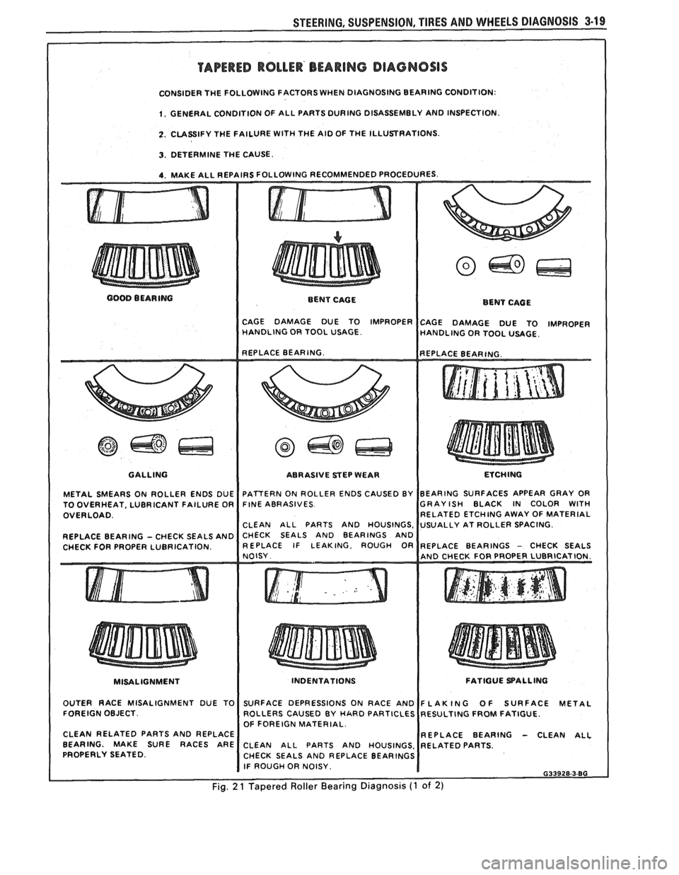
TAPERED ROLLER' BEARING DIAGNOSIS
CONSIDER THE FOLLOWING FACTORS WHEN DIAGNOSING BEARING CONDITION:
1. GENERAL CONDITION OF ALL PARTS DURING DISASSEMBLY AND INSPECTION.
2. CLASSIFY THE FAILURE WITH THE AID OF THE ILLUSTRATIONS.
3. DETERMINE THE CAUSE.
4. MAKE ALL REPAIRS FOLLOWING RECOMMENDED PROCEDURES.
GOOD BEARING
BENT CAGE
BENT CAGE
CAGE DAMAGE DUE TO IMPROPER
CAGE DAMAGE DUE TO )MPROPER HANDLING OR TOOL USAGE.
HANDLING OR TOOL USAGE.
GALLING
METAL SMEARS ON ROLLER ENDS DUE
TO OVERHEAT, LUBRICANT FAILURE OR
OVERLOAD.
REPLACE BEARING
- CHECK SEALS AND
CHECK FOR PROPER LUBRICATION. ABRASIVE
STEP WEAR
I ETCHING
FINE ABRASIVES GRAYISH BLACK IN COLOR
WITH RELATED ETCHING AWAY OF MATERIAL
CHECK SEALS AND BEARINGS AND
MISALIGNMENT
I
INDENTATIONS FATIGUE PALLING
OUTER RACE MISALIGNMENT DUE TO
FOREIGN OBJECT.
CLEAN RELATED PARTS AND REPLACE
BEARING. MAKE SURE RACES ARE
PROPERLY SEATED. SURFACE
DEPRESSIONS ON RACE AND
ROLLERS CAUSED BY
HARD PARTICLES
OF FOREIGN MATERIAL.
REPLACE BEARING
- CLEAN ALL CLEAN ALL PARTS AND HOUSINGS.
CHECK SEALS AND REPLACE BEARINGS
I IF ROUGH OR NOISY. I 633928.3-80
Fig. 2 1 Tapered Roller Bearing Diagnosis (1 of 2)
Page 148 of 1825
-
WHEEL. ALIGNMENT 3A-1
SECTION 3A
WHEEL AL GNMENT
NOTICE: These fasteners are important attaching Do not use a replacement part of lesser quality or
parts, in that they could affect the performance of substitute
design. Torque values must be used as
vital components and systems, and/or could result specified during reassembly to assure proper
in major repair expense. They must be replaced retention of these parts. For prevailing torque
with one of the same part number or with an
nut(s) and bolt(s), refer to the "Reuse of Prevailing
equivalent part if replacement becomes necessary. torque
Nut(s) and Bolt(s)" chart in Section 0.
General Description ...................... .. ...... 3A- 1 On-Car Service ........................ .. ........... 3A-2
Caster .................... .. ............................ 3A- 1 Caster and Camber Adjustment .................. 3A-2
..................................... Camber ................... .. .............................. 3A-I Toe-In Adjustment 3A-2
Toe.. ................................................. 3A- 1 Axle Housing Alignment ......................... .... 3A-4
Preliminary Checks Prior to Specifications ....................... ... ............... 3A-4
Adjusting Alignment ..................... ...... 3A- 1
GENERAL DESCRIPmIOMI
Wheel alignment refers to the angular they tend to roll parallel on the road when the car is
relationship between the wheels, the suspension moving.
attaching parts and the ground.
PRELIMINARY CHECKS PRIOR TO ADJUSTING
CASTER ALIGNMENT
Figure 1
Caster is the amount the top of the strut is tilted
forward or rearward from the vertical. When the strut
tilts rearward, the center is "positive"
(+). The
amount of tilt is measured in degrees from vertical.
CAMBER
Figure 1
Camber is the tilting of the wheels from the
vertical when viewed from the front of the car. When
the wheels tilt outward at the top, the camber is said
to be positive
(+). When the wheels tilt inward at the
top, the camber is said to be negative
(-). The amount
of tilt is measured in degrees from the vertical and this
measurement is called the camber angle.
TOE
Figure i
Toe is a measurement of how much the front of
the wheels are turned in or out from a straight-ahead
position. When the wheels are turned in, toe is
"positive"
(+). When the wheels are turned out, toe
is "negative"
(-). The actual amount of toe-in is
normally only a fraction of a degree. The purpose of a
toe specification is to ensure parallel rolling of the
wheels (excessive toe-in or toe-out may increase tire
wear). Toe also serves to offset the small deflections of
the wheel support system which occur when the car is
rolling forward. In other words, even when the wheels
are set to toe-in slightly when the car is standing still, Steering
and vibration complaints are not always
the result of improper alignment. Another possibility
is tire "lead" due to worn or improperly manufactured
tires. "Lead" is the deviation of the car from a straight
path on a level road without hand pressure on the
steering wheel. Section
3 of this manual contains a
procedure for determining the presence of a tire lead
problem.
Before making any adjustment affecting wheel
alignment, make the following checks to ensure correct
alignment readings and alignment adjustments:
1. Check all tires for proper inflation pressures and
approximately the same tread wear.
2. Hub and bearing assemblies for excessive wear;
correct if necessary.
3. Ball joints and tie rod ends; if they are excessively
lcose, correct them before adjusting.
4. Run-out of wheels and tires.
5. Car trim height; if out of limits and a correction
is to be made, do so before adjusting alignment.
Refer to Section
3 for trim height specifications.
6. Strut dampeners for proper operation.
7. Control arms for loose bushings.
8. Loose or missing stabilizer bar attachments.
Consideration must be given to excess loads, such
as tool boxes, sample cases, etc. If these items are
normally carried in the car, they should remain in the
car during alignment adjustments. Consideration
should also be given to the condition of the equipment
used to adjust alignment. Be sure to follow the
equipment manufacturer's instructions. Regardless
of