1988 PONTIAC FIERO oil filter
[x] Cancel search: oil filterPage 1120 of 1825
AUTOMATIC TMNSMISSION ON-VEHICLE SERVICE 7A1-1
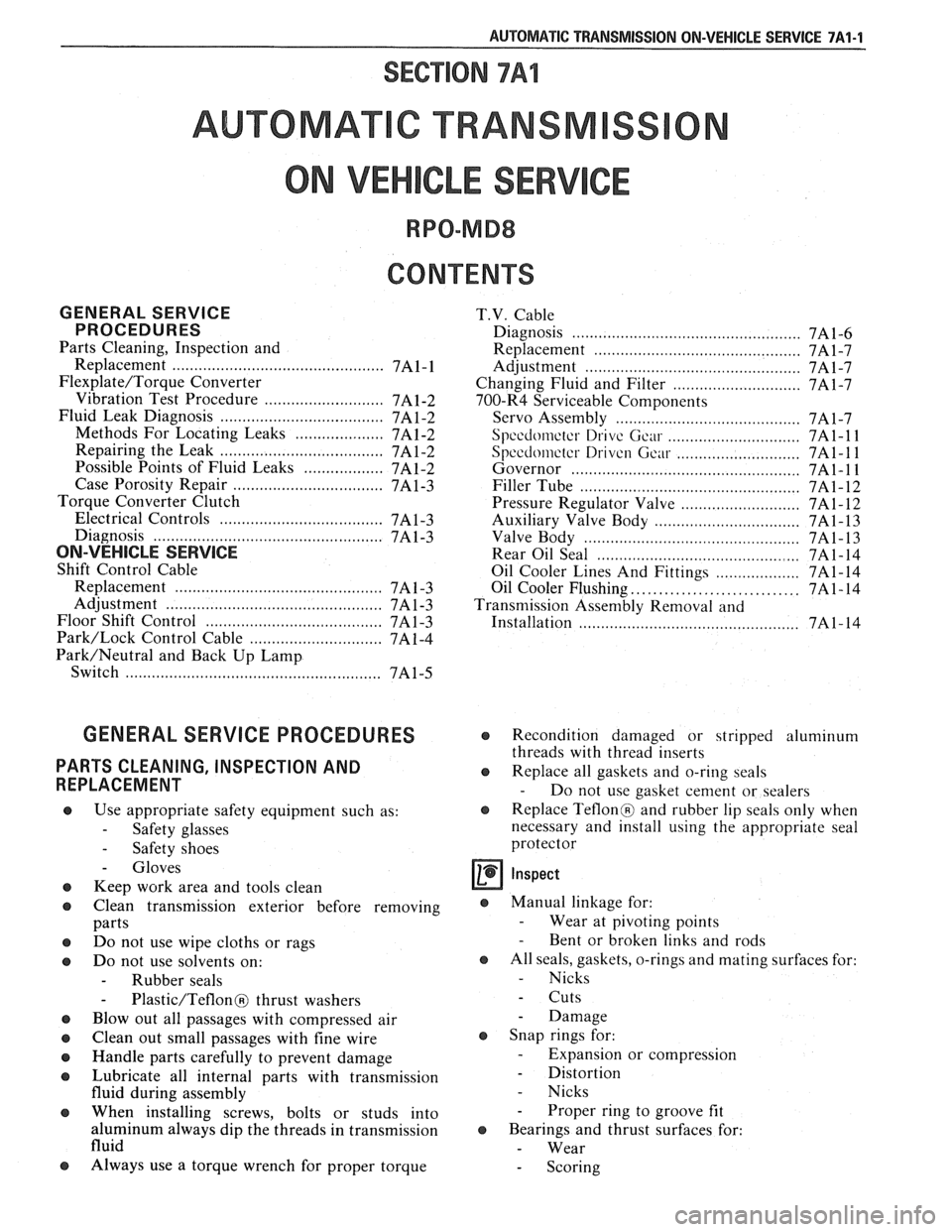
SECTION 7Al
AUTOMAT C TRANSM
ON VEH CLE SERV
CONTENTS
GENERAL SERVICE T.V. Cable
PROCEDURES Diagnosis ........................ .. ....................... 7A 1-6
Parts Cleaning, Inspection and
Replacement
....................................... 7A1-7
Replacement
............................ ... .... 7A1- 1 Adjustment ............................................. 7A1-7
Flexplate/Torque Converter Changing Fluid and Filter ............................. 7A1-7
........................... Vibration Test Procedure 7A1-2 700-R4 Serviceable Components
Fluid Leak Diagnosis
..................................... 7A 1-2
Servo Assembly .......................................... 7A 1-7
Methods For Locating Leaks
.................... 7Al-2 Speedometer Drive Gear .............................. 7A 1-1 1
Repairing the Leak .................................. 7A 1-2 Spccdomctcr Driven Gciu .......................... 7A1-1 1 Possible Points of Fluid Leaks .................. 7A1-2 Governor ............................................. 7A 1- 1 1
Case Porosity Repair .................................. 7A 1-3 Filler Tube .............................................. 7A1-12
Torque Converter Clutch
Pressure Regulator Valve
........................... 7A 1- 12
Electrical Controls
.................................. 7Al-3
Auxiliary Valve Body ................................. 7A1-13
Diagnosis
................................... .... ........ 7A 1-3 Valve Body ............................................. 7A 1- 13
ON-VEHICLE SERVICE Rear Oil Seal ............................................ 7A 1- 14
Shift Control Cable
Oil Cooler Lines And Fittings
................... 7A1-14
Replacement
............................................ 7A 1-3 Oil Cooler Flushing .............................. 7A 1 - 14 ................................................ Adjustment 7A1-3 Transmission Assenlbly Removal and
Floor Shift Control
................... .. ................ 7A1-3
Installation ........................... .. ............ 7A1- 14
Park/Lock Control Cable .............................. 7A 1-4
Park/Neutral and Back Up Lamp
Switch
................................................. 7A1-5
GENERAL SERVICE PROCEDURES
PARTS CLEANING, INSPECTION AND
REPLACEMENT
Use appropriate safety equipment such as:
- Safety glasses
- Safety shoes
- Gloves
Keep work area and tools clean
Clean transmission exterior before removing
parts
Do not use wipe cloths or rags
Do not use solvents on:
- Rubber seals
- Plastic/Teflon@ thrust washers
Blow out all passages with compressed air
Clean out small passages with fine wire
Handle parts carefully to prevent damage
Lubricate all internal parts with transmission
fluid during assembly
When installing screws, bolts or studs into
aluminum always dip the threads in transmission
fluid
Always use a torque wrench for proper torque
€3 Recondition damaged or stripped aluminum
threads with thread inserts
@ Replace all gaskets and o-ring seals
- Do not use gasket cement or sealers
@ Replace Teflon@ and rubber lip seals only when
necessary and install using the appropriate seal
protector
s Manual linkage for:
- Wear at pivoting points - Bent or broken links and rods
s All seals, gaskets, o-rings and mating surfaces for:
- Nicks
- Cuts
- Damage
€3 Snap rings for:
- Expansion or compression
- Distortion
- Nicks
- Proper ring to groove fit
s Bearings and thrust surfaces for:
- Wear
- Scoring
Page 1126 of 1825
AUTOMATIC TRANSMISSION ON-VEHICLE SERVICE 7A1-7
7. Place
gear selector into "DRIVE". Oil Pressure
should be equal or not more than 10 psi
(34 kPa)
higher than in "PARK".
8. Increase engine speed to 1400 RPM. If oil
pressure does not increase, adjust
T.V. cable.
Refer to T.V. Cable Adjustment.
Remove or Disconnect (Figs. 5 thru 7)
1. Air cleaner.
2. T.V. cable terminal from throttle lever.
3. Cable housing from bracket while compressing
locking tangs.
4. Routing clips or straps.
5. Raise
car, see Section OA.
6. Bolt securing T.V. cable to transmission.
o Pull up on cable cover at transmission until
cable is visible.
7. Cable from transmission link.
8. Cable seal.
Install or Connect
1. New seal into transmission case hole.
2. Transmission end of cable to T.V. link and secure
to transmission case with bolt and washer
assembly. Torque to 10
Nam (7 Ib. ft.).
3. Cable routing clips or straps.
4. Lower car.
5. Pass cable through engine bracket and engage
locking tangs of cable on bracket.
6. Avoid damaging or kinking wire cable.
7. Cable terminal to throttle lever.
Inspect
o Pull on upper end of cable. It should travel
a short distance with light resistance caused
by the small return spring on the
T.V. lever.
When releasing the upper end of the T.V.
cable, it should return to the zero T.V.
position.
Adjust
o T.V. cable. Refer to Figs. 5 thru 7.
CHANGING FLUID AND FILTER
Remove or Disconnect
1. Raise the car and support properly, see Section
OA.
2. Place drain pan under transmission oil pan.
3. Oil pan bolts from the front and sides only.
4. Loosen rear oil pan bolts approximately 4 turns.
NOTICE: Do not damage the transmission case
or oil pan sealing surfaces.
5. Lightly tap oil pan with rubber mallet or pry to
allow fluid to drain.
- Inspect fluid color
- Refer to chart in Section 7A
6. Remaining oil pan bolts, oil pan and gasket. 7. Oil filter
and o-ring
- O-ring may be stuck in the case
e Transmission case and oil pan gasket
surfaces with solvent and air dry.
- All traces of old gasket material must
be removed
Install or Connect
o Coat o-ring seal with a small amount of
petrolatum
o New o-ring onto filter
e New filter into case
a Oil pan and new gasket
e Oil pan bolts 20 N.m (15 lbs. ft.)
8. Lower car.
9. Fill transmission to proper level with
DEXRONO I1 fluid or equivalent, see Section
7A.
10. Check "Cold"
fluid level reading for initial till.
Do not overfill.
11. Follow
the "Transmission Fluid Level Checking
Procedure" in Section 7A of this Service Manual.
12. Check
oil pan gasket for leaks.
700-R4 SERVICEABLE COMPONENTS
The following parts can be serviced with the
transmission in the vehicle:
o Throttle valve control cable and/or sleeve heal
Fill tube and/or seal
o Governor assembly
a Speedometer drive and/or driven gear
e Servo assembly
a Valve body assembly, spacer plate, gaskets,
throttle lever and bracket assembly, auxiliary
valve body, TCC solenoid, switch and
wir-iug.
a Converter to flexplate bolts.
a Oil pan and/or gasket, strainer assembly and "0"
ring.
e Pressure Regular Valve.
o Rear Oil Seal.
SERVO ASSEMBLY
Remove or Disconnect (Fig. 8)
Tool Required:
J 29714-A
1. Raise car and suitably support, see Section OA.
2. Torque Arm,
see Section
3D.
3. Propeller Shaft, see Section 4A.
4. Exhaust hanger.
5. Support transmission.
6. Crossmember and transmission moulll.
7. Two
transmission oil pan bolts below servo cover.
8. Install J 29714-A on oil pan and reinstall oil pan
bolts.
9. Depress servo cover
and remove retaining ring.
10. J 29714-A.
Page 1132 of 1825
AUTOMATIC TRANSMISSION ON-VEHICLE SERVICE 7A1-13
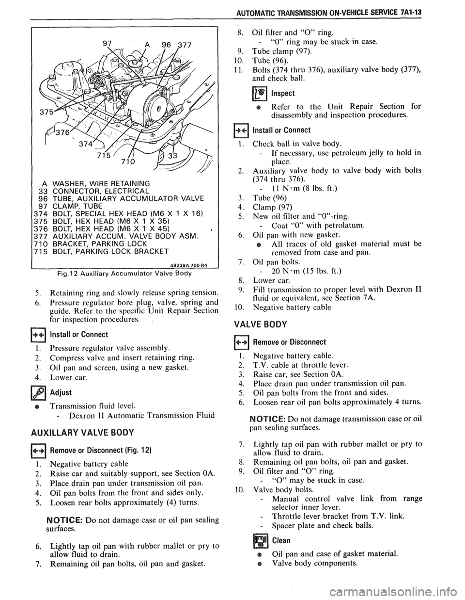
A WASHER, WIRE RETAINING
33 CONNECTOR, ELECTRICAL
96 TUBE, AUXILIARY ACCUMULATOR VALVE
97 CLAMP, TUBE
374 BOLT, SPECIAL HEX HEAD (M6
X 1 X 161
375 BOLT, HEX HEAD lM6
X 1 X 35)
376 BOLT, HEX HEAD lM6 X 1 X 45) , 377 AUXILIARY ACCUM. VALVE BODY ASM. 710 BRACKET, PARKING LOCK
71 5 BOLT, PARKING LOCK BRACKET
Fig. I2 Auxiliary Accumulator Valve Body
5. Retaining ring and slowly release spring tension.
6. Pressure regulator bore plug, valve, spring and
guide. Refer to the specific Unit Repair Section
for inspection procedures.
Install or Connect
1. Pressure regulator valve assembly.
2. Compress valve and insert retaining ring.
3. Oil pan
and screen, using a new gasket.
4. Lower car.
Adjust
cs Transmission fluid level.
- Dexron I1 Automatic Transmission Fluid
AUXILLARY VALVE BODY
Remove or Disconnect (Fig. 12)
I. Negative battery cable
2. Raise car and suitably support, see Section OA.
3. Place drain
pan under transmission oil pan.
4. Oil pan bolts from the front and sides only.
5. Loosen rear bolts approximately (4) turns.
NOTICE: Do not damage case or oil pan sealing
surfaces.
6. Lightly tap oil pan with rubber mallet or pry to
allow fluid to drain.
7. Remaining oil pan bolts, oil pan and gasket.
8. Oil filter and "0" ring.
- "0" ring may be stuck in case.
9. Tube clamp (97).
10. Tube (96).
11. Bolts (374 thru
376), auxiliary valve body (377),
and check ball.
Inspect
e Refer to the Unit Repair Section for
disassembly and inspection procedures.
Install or Connect
Check ball in valve body.
- If necessary, use petroleum jelly to hold in
place.
Auxiliary valve body to valve body with bolts
(374 thru 376).
- 11 N-rn(8lbs.ft.)
Tube (96)
Clamp (97)
New oil filter and "OW-ring.
- Coat "0" with petrolatum.
Oil pan with new gasket.
All traces of old gasket material must be
removed from case and pan.
Oil pan bolts.
- 20 Nem (15 Ibs. ft.)
Lower car.
Fill transmission to proper level with Dexron
I1
fluid or equivalent, see Section 7A.
Negative battery cable
VALVE BODY
Remove or Disconnect
1. Negative battery cable.
2. T.V. cable at throttle lever.
3. Raise car, see Section OA.
4. Place
drain pan under transmission oil pan.
5. Oil pan bolts from the front and sides.
6. Loosen
rear oil pan bolts approximately 4 turns.
NOTICE: Do not damage transmission case or oil
pan sealing surfaces.
7. Lightly
tap oil pan with rubber mallet or pry to
allow fluid to drain.
8. Remaining oil pan bolts, oil pan and gasket.
9. Oil
filter and
"0" ring.
- "0" may be stuck in case.
10. Valve body bolts.
- Manual control valve link from range
selector inner lever.
- Throttle lever bracket from T.V. link.
- Spacer plate and check balls.
Oil pan and case of gasket material.
e Valve body components.
Page 1133 of 1825
7A1-44 AUTOMATIC TRANSMISSION ON-VEHICLE SERVICE
Inspect
e Refer to the Unit Repair Section for
disassembly and inspection procedures.
Install or Connect
1. Valve body, spacer, check balls and bolts as
outlined in the Unit Repair Section.
2. New
"0" ring
seal and oil filter.
- Coat "0" ring seal with petrolatum.
3. New gasket, oil pan and bolts.
- 20 N.m (15 lbs. ft.)
4. Lower car.
5. Fill
transmission to proper level with Dexron
I1
fluid or equivalent, see Section 7A.
Adjust
e T.V. cable, see Figs. 5 thru 7.
REAR OIL SEAL
Remove or Disconnect
Tool Required:
J 21426 Seal Installer
1. Raise car and suitably support, see Section OA.
2. Propeller shaft, see Section 4A.
3. Pry out lip seal with a suitable tool.
Install or Connect
I. Coat outer casing of new lip oil seal with
non-hardening sealer and tap in place with
J
2 1426.
2. Propeller
shaft, see Section 4A.
3. Lower car.
Adjust
e Transmission fluid level.
- Dexron 11 Automatic Transmission Fluid
OIL COOLER LINES AND/OR FITTINGS
Figs. 13 and 14
If replacement of transmission cooler lines is
required, use only double wrapped and brazed steel
tubing meeting
GM specification 123M or equivalent.
Tubing should be double flared.
NOTICE: Allow sufficient clearance around
cooler lines to prevent damage or wear which may
cause fluid loss.
OIL COOLER FLUSHING
Tools Required:
J 35944 Cooler Flushing Tool
J 35944-20 Flushing Solution
Water Supply
Air Supply (with water and oil fil-
ter)
Oil Drain Container
5 Gallon Pail
1. Remove the fill cap on J 35944 and fill with .6
liters (20-21 ounces) of J 35944-20 flushing
solution.
@ Do not over fill
@ Follow manufacture's suggested proce-
dures for solution handling.
Replace cap on
J 35944 and pressurize it to 550-
700
kPa (80-100 psi).
Connect
J 35944 to the transaxle end of the oil
cooler pipe that feeds the BOTTOM fitting of
the oil cooler.
Connect the discharge hose to the TOP oil
cooler pipe and clip the discharge hose to the oil
drain container.
With the water valve on
J 35944 in the "off'
position, connect the water supply to the tool.
Turn the water valve off.
Flush the transaxle fluid by opening the water
valve to the "on" position for about 10 seconds.
Important
@ If water does not flow thru the cooler the
system is completely plugged. Do not
complete the flushing procedure. Replace
the cooler
and/or the cooler pipes as
required.
8. Close the water valve and clip the discharge
hose to the 5 gallon pail. Cover the pail with a
shop towel to prevent splash.
9. Turn the water valve to
the
"on" positon and
depress the trigger to mix flushing solution into
the water flow. Use the bail clip provided to
hold the trigger down.
10. Flush the
cooler with water and solution for 2
minutes. During this flush, attach the air supply
to the air valve located on the tool, for 3 to 5
seconds every 15-20 seconds. This will create a
surging action to ensure complete cleaning.
11. Release the trigger and turn the water valve off.
12. Disconnect both hoses from the oil cooler pipes.
13. Reconnect the hoses to the pipes opposite the
initial flush to preform a backflush.
14. Repeat steps 9 and 10
15. Release the trigger and allow water to rinse
for
one minute.
16. Turn the water valve off.
17. Attatch the air supply to the air valve and dry the
system out with air until no moisture is seen
leaving the discharge hose.
18. Connect the Cooler Feed Pipe to the transaxle.
19. Clip the discharge hose to the oil drain con-
tainer.
20. After filling the transaxle with
fluid,
start the
engine and run for 30 seconds. This will remove
any residual
moistrue from the oil cooler. A
minimum of 2 quarts of fluid should flow during
the 30 second period. If fluid flow is sufficient,
check the fluid flow by disconnecting the feed
Page 1410 of 1825
INSTRUMENT PANEL: GAGES CLUSTER
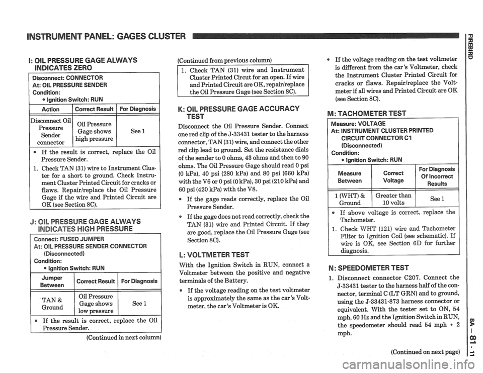
I: OIL PRESSURE GAGE ALWAYS
lEUDlCATES ZERO
At: OIL PRESSURE SENDER
Condition:
lanition Switch: RUN
Action
I Correct Result I For Diagnosis
If the result is correct, replace the Oil
Pressure Sender.
1. Check TAN (31) wire to Instrument Clus-
ter for a short to ground. Check Instru-
ment Cluster Printed Circuit for cracks or
flaws. Repairlreplace the Oil Pressure
Gage if the wire and Printed Circuit are
OK (see Section
86).
Disconnect Oil
Pressure
Sender
J: 81L PRESSURE GAGE ALWAYS
INDICATES
HBGH PRESSURE
(Disconnected)
high pressure
connector
Oil Pressure
Gage shows (Continued
from previous column)
See 1
Cluster Printed Circut for an open. If wire
K: OIL PRESSURE GAGE ACCURACY
TEST
Disconnect the Oil Pressure Sender. Connect
one red clip of the
5-33431 tester to the harness
connector, TAN (31) wire, and connect the other
red clip lead to ground. Set the resistance dials
of the sender to 0 ohms, 43 ohms and then to 90
ohms. The Oil Pressure Gage should read 0 psi
(0
Wa), 40 psi (280 kPa) and 80 psi (660 kPa)
with the V6 or 0 psi (0 kPa), 30 psi (210 kPa) and
60 psi (420
kPa) with the V8.
r If the gage reads correctly, replace the Oil
Pressure Sender.
@ If the gage does not read correctly, check the
TAN (31) wire and Printed Circuit. If they
are good, replace
the Oil Pressure Gage (see
Section 89.
L: VOLTMETER TEST
With the Ignition Switch in RUN, connect a
Voltmeter between the positive and negative
als of the Battery.
If the voltage reading on the test voltmeter
is
approfimately the same as the car's Volt-
meter, the car's Voltmeter is OK. If
the voltage reading on the test voltmeter
is different
from the car's Voltmeter, check
the Instrument Cluster Printed Circuit for
cracks or flaws. Repairlreplace the Volt-
meter if
all wires and Printed Circuit are OK
(see Section 8C).
M: TACHOMETER TEST
At: INSTRUMENT CLUSTER PRINTED
CIRCUIT CONNECTOR 61
(Disconnected)
Condition:
I @ Ignition Switch: RUN I --
For Diagnosis
Of incorrect
Between Results
1 (WRT) & Greater than See Ground 10 volts
@ If above voltage is corred, replace the
Tachometer.
1. Check WHT (121) wire md Tachometer
Filter to
Ignition Coil (see schematic). If
wire is OK, see Section 6D for further
diagnosis.
N: SPEEDOMETER TEST
1. Disconnect connector C207. Connect the
5-33431 tester to the harness half of the con-
nector,
terminal C (LT GRN) and to ground,
using the
5-33431-873 harness connector or
equivalent. With the tester set to ON, 54
mph, 60
HZ and the Ignition Switch in RUN,
the speedometer should read 54 mph
+ 2
mph.
(Continued
in next column)
(Continued on next page)
Page 1428 of 1825
INSTRUMENT PANEL: DIGITAL CLUSTER n 23 rn E
ClRCUlT OPERATION
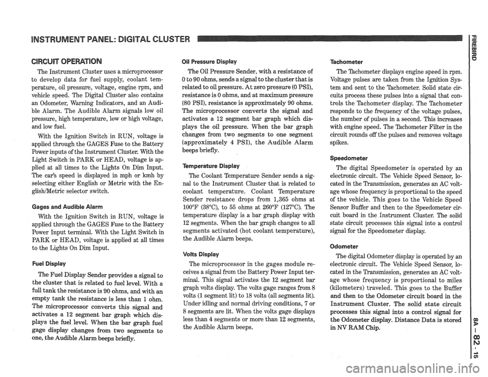
The Instrument Cluster uses a microprocessor
to develop data for fuel supply, coolant tem-
perature, oil pressure, voltage, engine rpm, and
vehicle speed. The Digital Cluster also contains
an Odometer, Warning Indicators, and an Audi-
ble Alarm. The Audible Alarm signals low oil
pressure, high temperature, low or high voltage,
and low fuel.
With the Ignition Switch in RUN, voltage is
applied through the GAGES Fuse to the Battery
Power inputs of the Instrument Cluster. With the
Light Switch in PARK or HEAD, voltage is ap-
plied at all times to the Lights On Dim Input.
The car's speed is displayed in mph or
krnh by
selecting either English or Metric with the
En-
glishNetric selector switch.
Gages and Audible Alarm
With the Ignition Switch in RUN, voltage is
applied through the GAGES Fuse to the Battery
Power Input terminal. With the Light Switch in
PARK or HEAD, voltage is applied at all times
to the Lights On Dim Input.
Fuel Display
The Fuel Display Sender provides a signal to
the cluster that is related to fuel level. With a
full tank the resistance is 90 ohms, and with an
empty tank the resistance is less than
1 ohm.
The microprocessor converts this signal and
activates a 12 segment bar graph which dis-
plays the fuel level. When the bar graph fuel
gage display changes from two segments to
one, the Audible Alarm beeps briefly.
Oil Pressure Display
The Oil Pressure Sender, with a resistance of
0 to 90 ohms, sends a signal to the cluster that is
related
to oil pressure. At zero pressure (0 PSI),
resistance is 0 ohms, and at maximum pressure
(80 PSI), resistance is approximately 90 ohms.
The microprocessor converts the signal and
activates a 12 segment bar graph which dis-
plays the oil pressure. When the bar graph
changes from two segments to one segment
(approximately
4 PSI), the Audible Alarm
beeps briefly.
kmperature Display
The Coolant Temperature Sender sends a sig-
nal to the Instrument Cluster that is related to
coolant temperature. Coolant Temperature
Sender resistance drops from 1,365 ohms at
100°F
(38"C), to 55 ohms at 260°F (127°C). The
temperature display is a bar graph display with
12 segments. When the bar graph changes to all
segments activated (hot coolant temperature),
the Audible Alarm beeps.
Volts Display
The microprocessor in the gages module re-
ceives a signal from the Battery Power Input ter-
minal. This signal activates the 12 segment bar
graph volts display. The volts gage ranges from 8
volts
(1 segment lit) to 18 volts (all segments lit).
Under idling and normal driving conditions, 7 or
8 segments are lit. When the volts gage displays
less than
4 segments or more than 12 segments,
the Audible Alarm beeps.
Tachometer
The Thchometer displays engine speed in rpm.
Voltage pulses are taken from the
Ignition Sys-
tem and sent to the Tachometer. Solid state cir-
cuits process these pulses into a signal that con-
trols the Tachometer display. The Tachometer
responds to the frequency of the voltage pulses,
the number of pulses in a second. This increases
with engine speed. The
'Pdchometer Filter in the
circuit rounds off the pulses and removes voltage
spikes.
Speedometer
The digital Speedometer is operated by an
electronic circuit. The Vehicle Speed Sensor, lo-
cated in the Transmission, generates an AC volt-
age whose frequency is proportional to the speed
of the vehicle. This goes to the Vehicle Speed
Sensor Buffer and then to the Speedometer cir-
cuit board in the Instrument Cluster. The solid
state circuit processes this signal into a control
signal for the Speedometer display.
Odometer
The digital Odometer display is operated by an
electronic circuit. The Vehicle Speed Sensor, lo-
cated in the Transmission, generates an
AC volt-
age whose frequency is proportional to miles
(kilometers) traveled. This goes to the Buffer
and then to the Odometer circuit board in the
Instrument Cluster. The solid state circuit
processes this signal into a control signal for
the Odometer display. Distance Data is stored
in
NV RAM Chip.
Page 1553 of 1825
RADIO I
(Continued from previous page) from back of Radio
If noise persists with replacement antenna, the
problem must be repaired at the source of noise
(generator, ignition system, accessory, etc.). See
Delco Manual for noise "Sniffing" procedures.
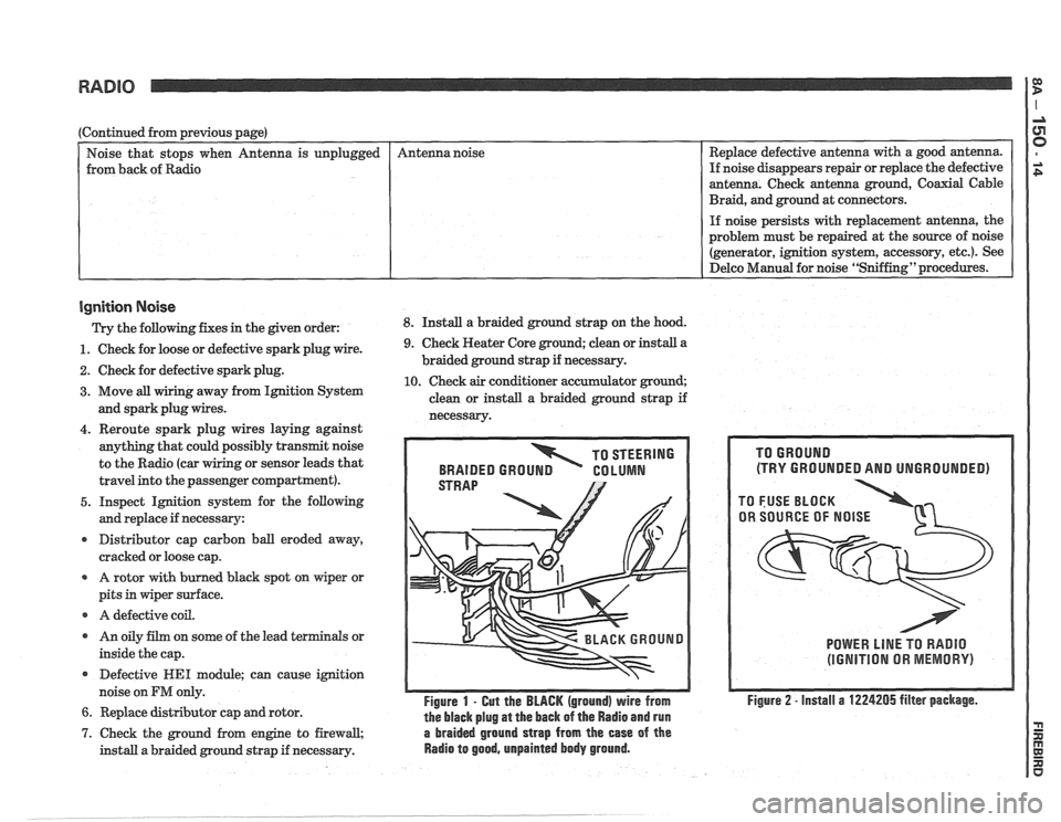
Ignition Noise
Trv the following. fixes in the piven order: 8. Install a braided ground strap on the hood. Replace
defective antenna with a good antenna.
If noise disappears repair or replace the defective
antenna. Check antenna ground, Coaxial Cable
Braid, and ground at connectors.
unplugged
- -
1. Check
for loose or defective spark plug wire.
2. Check for defective spark plug.
3. Move all wiring away from Ignition System
and spark plug wires. Antenna
noise
4. Reroute spark plug wires laying against
anything that could possibly transmit noise
to the Radio (car
g or sensor leads that
travel into the passenger compartment).
5. Inspect Ignition system for the following
and replace if necessary:
r Distributor cap carbon ball eroded away,
cracked or loose cap.
A rotor with burned black spot on wiper or
pits in wiper surface.
r A defective coil.
r An oily film on some of the lead terminals or
inside the cap.
Defective
WE1 module; can cause ignition
noise on
FM only.
6. Replace distributor cap and rotor.
9. Check Heater Core ground; clean or install a
braided ground strap if necessary.
10. Check air conditioner accumulator ground;
clean or install a braided ground strap if
necessarv.
TO STEERING
BRAIDED
GROUN GO LUMN
Figure 1 - Gut the BLACK (ground) wire from
the black plug
at the back of the Radio and run
7. Check the ground from engine to firewall, a braided ground strap from the ease of the
install a braided ground strap if necessary. Radio to good, unpainted body ground.
(TRY GROUNDED AND UNGROUNDED)
POWER LlNE TO RADIO
(IGNITION OR MEMORY)
Figure 2 - install a 1224205 filter package.
Page 1674 of 1825
MISCELLANEOUS ACCESSORIES 96-4
SCELLANEOUS ACCESSOR
General Description ................................. 9G-1
Rally Gages .................................................. 9G- 1
Tachometer ................................................. 9G- 1
Trip Odometer
............................................. 9G- 1
Electric Rear Window Defogger ................. 9G-2
Power Remote Control Rearview
Mirror ........................................................ 9G-2
Diagnosis .................................................... 9G-2
Rally Gages ............................................... 9G-2
Tachometer .................................... .... .... 9G-2
Electric Rear Window Defogger ................. 9G-2
Power Remote Control Rearview
Mirror ........................................................ 96-2
Dash and Console Mounted
Accessory Switches
................................. 9G-4
General Description .................................. 9G-4
Electronic Glare Control Mirror ................. 9G-4
On-Car Service ............................................. 9G-4
Rally Gages, Tach ....................................... 96-4.
Rear Window Defogger ............................ 96-4.
Power Remote Control Mirror .................... 9G-4
GENERAL BESCRIP"T0N
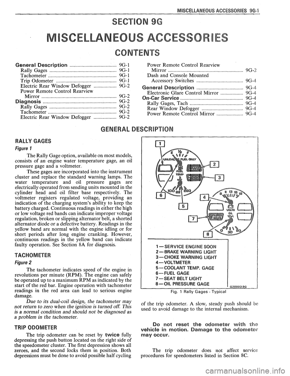
RALLY GAGES
Figure I
The Rally Gage option, available on most models,
consists of an engine water temperature gage, an oil
pressure gage and a voltmeter.
These gages are incorporated into the instrument
cluster and replace the standard warning lamps. The
water temperature and oil pressure gages are
electrically operated from sending units mounted in the
cylinder head and oil filter base respectively. The
voltmeter registers regulated voltage, providing an
indication of the charging system's ability to keep the
battery charged. Continuous readings in either the high
or low voltage red bands can indicate improper voltage
regulation, broken or slipping alternator belt,
a shorted
alternator diode
or a defective battery. Readings in the
yellow band are normal with the engine idling or for
short periods after long engine cranking. However,
continuous readings in the yellow band can indicate
faulty operation. See Section
8A for diagnosis.
TACHOMETER
Figure 2
The tachometer indicates speed of the engine in
revolutions per minute (RPM). The engine can safely
be operated up to a maximum RPM as indicated by the
start of the red bar. Engine operation with tachometer
readings in the red area can lead to serious engine
damage.
Due to its dual-coil design, the tachometer may
not return to zero when the ignition
is turned oft: This
is
a normal condition and should not be diagnosed as
a problem in the tachometer.
TRIP ODOMETER
The trip odometer can be reset by twice fully
depressing the push button located on the right side of
the speedometer cluster. The first depression shows all
zeroes, and the second locks them in position. Both
depressions must be done to avoid possible half cycling
I -SERVICE ENGINE SOON
2-BRAKE WARNING LIGHT
3-CHOKE WARNING LIGHT
4-VOLTMETER
5-COOUNT TEMP. GAGE
6-FUEL GAGE
7-SEAT BELT LIGHT
8-OIL PRESSURE GAGE G20003 9G
Fig. 1 Rally Gages - Typical
of the trip odometer. A slow, steady push should be
used to avoid damage to the internal mechanism.
Do not reset the odometer with the
vehicle in motion. Damage to the odometer
may occur.
The trip odometer does not affect service
procedures for speedometers listed in Section
8C.