1988 PONTIAC FIERO torque
[x] Cancel search: torquePage 173 of 1825
385-22 STEERING WHEELS AND COLUMNS
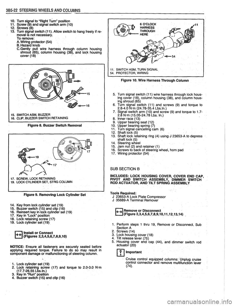
10. Turn si nal to "Right Turnn position 11. Screw f9) and signal switch arm (10) 12. crews (8) 13. Turn signal switch (11). Allow switch to hang freely if re- moval is not necessary.
To remove:
A. Wiring protector (54) B. Hanard knob C.Gently pull wire harness through column housing
shroud (65), column housing (38), and lock housing
cover (1 8)
5. Turn signal switch (I 1) wire harness through lock hous-
ing cover (18), column housing (38), and column hous-
ing shroud (65)
6. Turn signal switch (1 1) and screws (9) and torque to
2.8-4.0
N.m (24.78-35.4 Lbs.ln.) 7. Signal switch arm (10) and screw (9) and torque to 1.7- 2.8 N.m (1 5.05-24.78 Lbs. In.)
8. Inner race (13)
9. Upper bearing seat (12)
10. Upper bearing spring (7)
11. Turn signal cancelling cam (6)
12. Shaft lock (5)
13. Shaft lock retaining ring (4) using J 23653-A to depress
shaft lock (5)
14. Steering wheel
15. Jam nut (2) and retainer
(1) 16. Screws to back of steering wheel, horn pad
17. Wiring protector (54)
SUB SECTION 6
17. SCREW, LOCK RETAINING INCLUDES:
LOCK HOUSING COVER, COVER END CAP, 19. LOCK CYLINDER SET, STRG COLUMN PIVOT
AND SWITCH ASSEMBLY, DIMMER SWITCH
ROD ACTUATOR, AND TILT SPRING ASSEMBLY
Flgurs 9. Rsmovlng Lock Cylinder Set Tools
Required:
J 23653-A Lock Plate Compressor
J 35689-A Terminal Remover
14. Key from lock cylinder set (19)
15.
Buuer switch (1 5) and clip (1 6)
16. Reinsert key in lock cylinder set (1 9) Remove
or Disconnect
17. Key in "Lock" position
m(Flgure 2,3,4,5,6,7,8,9,10,11,12,13,14) -
18. Lock retaining screw (1 7) 19. Lock cylinder set (1 9) 1. Perform steps 1 thru 19, Remove or Disconnect, Sub
Section A
lnsbll or Connect 2.
Screws (14)
m~(FIguns 2,3,4,56,7,(1,9,10) 3. Lock housing cover (1 8)
4. Tilt release lever (75)
5. Housing cover end cap
(44), and dimmer switch rod
NOTICE: Ensure all fasteners are securely seated before actuator (20)
applying required torque. Failure to do so may result in
component damage or malfunctioning of steering column.
lmporlant
Cruise control equipped columns: Unplug cruise
1. Lock cylinder set
(1 9) control
connector and remove multifunction lever 2. Lock retainin screw (17) and torque to 2.0-3.0 N-m (74).
(1 7.7-2~55 ~!s.ln.) 3. Key in "Runn position 4. Buner switch (1 5) and clip (1 6)
Page 174 of 1825
STEERING WHEELS AND COLUMNS 385.23
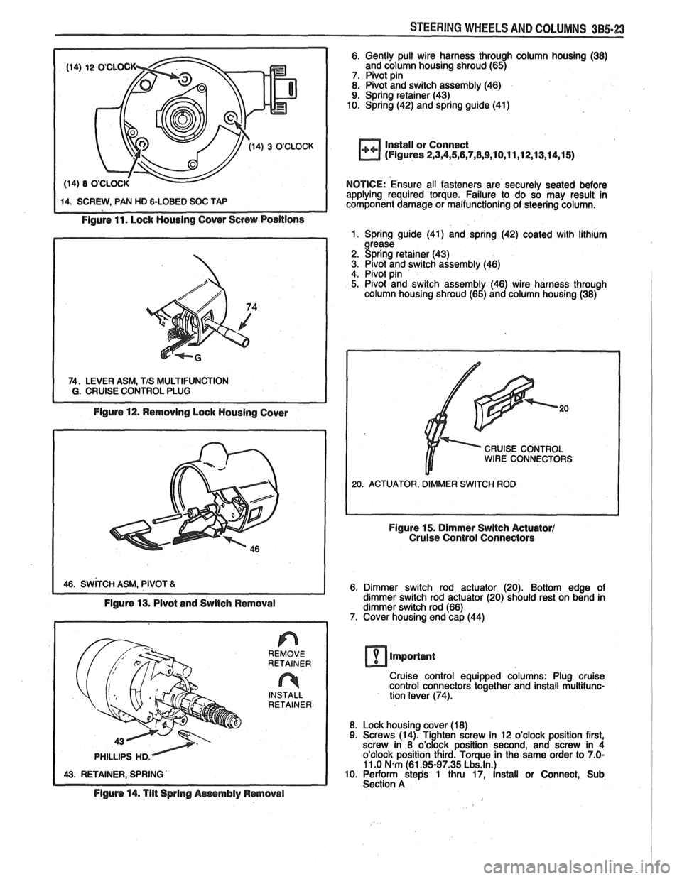
Figure 11. Lock Housing Cover Screw Positions
74. LEVER ASM, TIS MULTIFUNCTION I G. CRUISE CONTROL PLUG
Figure 12. Removing Lock Housing Cover
1 46. SWITCH ASM, PIVOT 81
Figure 13. Pivot and Switch Removal
REMOVE
RETAINER
n INSTALL
RETAINER
Flgum 14. Tilt Spring Aessmbly Removal
6. Gently pull wire harness throu h column housing (38)
and column housing shroud (657 7. Pivot pin 8. Pivot and switch assembly (46)
9. Spring retainer (43)
10. Spring (42) and spring guide (41)
Install or Connect
(Figures 2,3,4,5,6,7,8,9,10,11 ,12,13,14,1 5)
NOTICE: Ensure all fasteners are securely seated before
applying required torque. Failure to do so may result in
component damage or malfunctioning of steering column.
1. Spring guide (41) and spring (42) coated with lithium
2. !$;rK: retainer (43) 3. Pivot and switch assembly (46)
4. Pivot pin
5. Pivot and switch assembly (46) wire harness through
column housing shroud (65) and column housing (38)
CRUISE CONTROL WIRE CONNECTORS
Figure 15. Dimmer Switch Actuator1 Cruise Control Connectors
6. Dimmer switch rod actuator (20). Bottom edge of
dimmer switch rod actuator (20) should rest on bend in
dimmer switch rod (66)
7. Cover housing end cap (44)
important
Cruise control equipped columns: Plug cruise
control connectors together and install multifunc-
tion lever
(74).
8. Lock housing cover (18)
9. Screws (14). Tighten screw in 12 o'clock position first,
screw in 8 o'clock position second, and screw in 4
o'clock position third. Torque in the same order to
7.0- 11 .O N.m (61.95-97.35 Lbs.ln.) 10. Perform step's 1 thru 17, install or Connect, Sub
Section A
Page 175 of 1825
3B5-24 STEERING WHEELS AND COLUMNS
SUB SECTION C
INCLUDES: COLUMN HOUSING, LOCK SHOES, AC-
TUATOR SECTOR ASSEMBLY, SWITCH ACTUATOR
RACK, BEARINGS, AND LOCK BOLT ASSEMBLY
Tools Required: J 23653-A Lock Plate Compressor J 35689-A Terminal Remover J 21 854-Q1 Pivot Pin Remover
Remove or Disconnect
(Figure 2 thru 18)
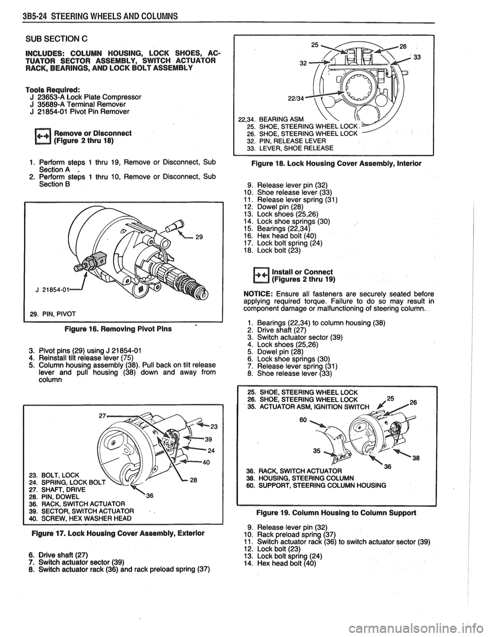
1. Perform stem 1 thru 19. Remove or Disconnect, Sub
Section A . 2. Perform steps 1 thru 10, Remove or Disconnect, Sub
Section B
BEARING ASM
SHOE, STEERING WHEEL LOCK.-/ SHOE, STEERING WHEEL LOCK
PIN. RELEASE LEVER
Figure 18. Lock Housing Cover Assembly, interior
9. Release lever pin (32)
10. Shoe release lever (33)
11. Release lever spring (31)
12. Dowel pin (28)
13. Lock shoes
(25,26) 14. Lock shoe springs (30)
15. Bearings (22,34) 16. Hex head bolt (40)
17. Lock bolt spring (24)
18. Lock bolt (23)
Install or Connect
(Figures 2 thru 19)
NOTICE:
Ensure all fasteners are securely seated before
applying required torque. Failure to do so may result in
component damage or malfunctioning of steering column.
1. Bearings
(22,34) to column housing (38) Flgure 16. Removing Pivot Pins 2. Drive shaft (27)
3. Switch actuator sector (39)
4. Lock shoes
(25,26) 3. Pivot pins (29) using J 21 854-01 5. Dowel pin (28)
4. Reinstall tilt release lever (75) 6. Lock shoe springs (30)
5. Column housing assembly (38). Pull back on tilt release 7. Release lever spring (31)
lever and pull housing (38) down and away from
8. Shoe release lever (33)
column
23. BOLT, LOCK 24. SPRING, LOCK BO 27. SHAFV, DRIVE 28. PIN, DOWEL 36. RACK, SWITCH ACTUATOR 39. SECTOR SWITCH ACTUATOR . .
36. RACK, SWITCH ACTU 38. HOUSING, STEERING 60. SUPPORT, STEERING
Figure 19. Column Housing to Column Supporl
9. Release lever pin (32) Flgum 17. Lock Housing Cover Assembly, Exlerlor 10. Rack preload spring (37) 11. Switch actuator rack (36) to switch actuator sector (39)
12. Lock bolt (23)
6. Drive shaft (27) 13. Lock bolt sprin (24)
7. Switch actuator sector (39)
14. Hex head bolt 740) 8. Switch actuator rack (36) and rack preload spring (37)
Page 177 of 1825
3B5-26 STEERING WHEELS AND COLUMNS
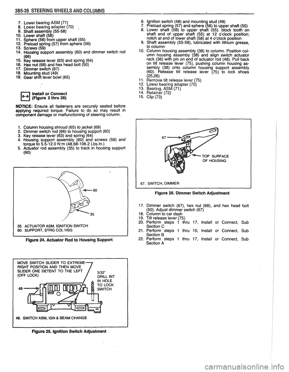
7. Lower bearing ASM (71)
8. Lower bearing adapter (70) - 9. Shaft assembly (55-58)
10. Lower shaft (58)
11. Sphere (56) from upper shaft (55) 12. Preload spring (57) from sphere (56)
13. Screws (59)
14. Housing support assembly (60) and dimmer switch rod
If%
15. i<'si release lever (63) and spring (64) 16. Hex nut (68) and hex head bolt (50)
17. Dimmer switch (67)
18. Mounting stud (49)
19. Gear shift lever bowl (65) Ignition switch (48)
and
mountin stud (49)
Preload spring (57) and sphere 156) to upper shaft (55)
Lower shaft (58) to upper shaft (55). block tooth on
shaft end of upper shaft (55) at 12 o'clock position;
notch at end of lower shaft (58) at 4 o'clock position
Shaft assembly
(55-58), lubricated with lithium grease,
to column
Column housing assembly (38) to column. Position col-
umn housing
assemby (38) and align switch actuator
rack (36) with pin on end of actuator rod (48). Pull back
on tilt release lever
(75), pushing column housing as-
sembly (38) onto column housing support assembly
(60). Release tilt release lever (75) to lock shoes
(2526) Remove tilt release lever 175) 12. Lower bearing adapter (70) '
13. Bearing, ASM (71)
In~bll or Connect 14. Retainer (72)
(Figure 2 thru 26) 15. Clip (73)
WTICE: Ensure all fasteners are securely seated before aaplying required torque. Failure to do so may result in component damage or malfunctioning of steering column.
1. Column housing shroud (65) to jacket (69)
2. Dimmer switch rod (66) to housing support (60)
3. Key release lever (63) and spring (64)
4. Housing support assembly (60) and screws (59) and
torque to
5.5-12.0 N.m (48.68-106.2 Lbs.ln.) 5. Actuator rod assembly (35) to track in housing support
(60)
35. ACTUATOR ASM, IGNITION SWITCH 60. SUPPORT, STRG COL HSG TOP
SURFACE
OF HOUSING
Figure 26. Dimmer Switch Adjustment
17. Dimmer switch (67), hex nut (68), and hex head bolt
(50). Adjust dimmer switch (67)
18. Column to car dash
19. Tilt release lever (75)
20. Perform steps 1 thru 17, Install or Connect, Sub
Section C
21. Perform steps 1 thru 10, Install or Connect, Sub
Section B
Figure 24. Actuator Rod to Housing Support 22. Perform steps 1 thru 17, Install or Connect, Sub
Section A
48. SWITCH ASM, IGN & BEAM CHANGE
Flgure 25. lgnitlon Switch Adjustment
Page 181 of 1825
385-30 STEERING WHEELS AND COLUMNS
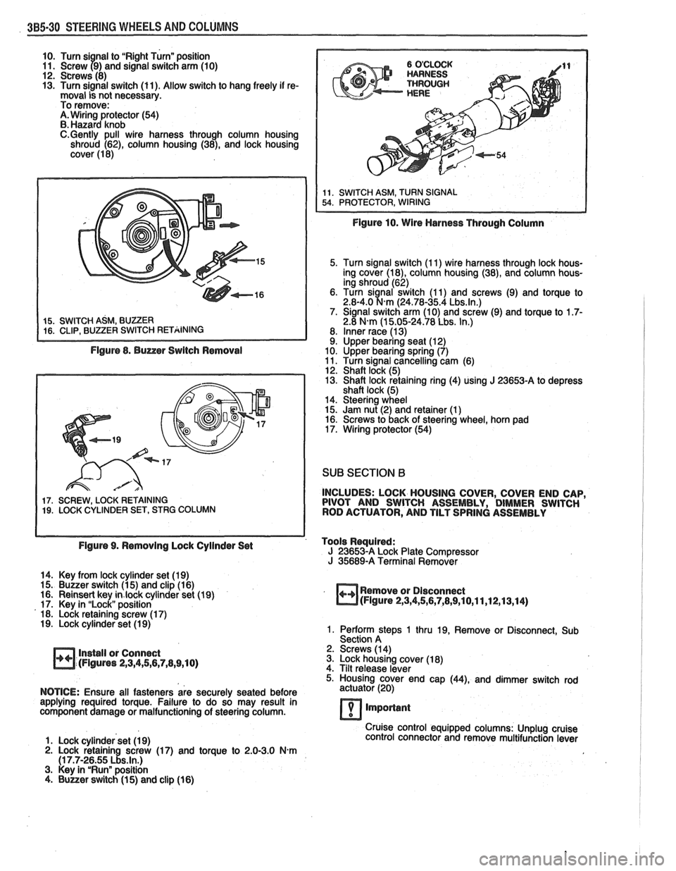
10. Turn si nal to "Right Turn" position
11. Screw 79) and signal switch arm (10)
12. Screws (8)
13. Turn signal switch (11). Allow switch to hang freely if re-
moval is not necessary.
To remove:
A. Wiring protector (54)
B. Hazard knob
C.Gently pull wire harness through column housing
shroud (62), column housing (38), and lock housing
cover (1 8)
Figure 8. Buzzer Switch Removal
17. SCREW, LOCK RETAINING 19. LOCK CYLINDER SET, STRG COLUMN
Figure 10. Wire Harness Through Column
5. Turn signal switch (1 1) wire harness through lock hous-
ing cover
(la), column housing (38), and column hous-
ing shroud (62)
6. Turn
sianal switch (1 1) and screws (9) and torque to 2.8-4.0 %km (24.78-35.4 Lbs.ln.) 7. Signal switch arm (10) and screw (9) and torque to 1.7- 2.8 N-m (1 5.05-24.78 Lbs. In.)
8. Inner race (1 3) 9. Upper bearing seat (1 2)
10. Upper bearing spring (7)
11. Turn signal cancelling cam (6)
12. Shaft lock (5)
13. Shaft lock retaining ring (4) using
J 23653-A to depress
shaft lock (5)
14. Steering wheel
15. Jam nut (2) and retainer (1
) 16. Screws to back of steering wheel, horn pad
17. Wiring protector (54)
SUB SECTION B
INCLUDES: LOCK HOUSING COVER, COVER END CAP,
PIVOT AND SWITCH ASSEMBLY, DIMMER SWITCH
ROD ACTUATOR, AND TILT SPRING ASSEMBLY
Figure 9. Removing Lock Cyilnder Set Tools
Rwuired: J 23653-A Lock
Plate Compressor J 35689-A Terminal Remover
14. Key from lock cylinder set (19)
15. Buzzer switch (1 5) and clip (1 6)
16. Reinsert key
in.lock cylinder set (19)
17. Key in "Lock" position
18. Lock retaining screw (1 7)
19. Lock cylinder set (1 9)
Install or Connect
(Figures
2,3,4,5,6,7,8,9,10)
Remove or Dlsconnect (Figure 2,3,4,5,6,7,8,9,10,11,12,13,14)
1. Perform steps 1 thru 19, Remove or Disconnect, Sub
Section A
2. Screws (1 4)
3. Lock housing cover (1 8)
4. Tilt release lever
5. Housing cover end cap
(44), and dimmer switch rod
NOTICE: Ensure all fasteners are securely seated before actuator
(20)
applying required torque. Failure to do so may result in
component damage or malfunctioning of steering column.
7 important
Cruise control equipped columns: Unplug cruise
1. Lock cylinder set (1 9) control
connector and remove multifunction lever
2. Lock retaining screw (17) and torque to 2.0-3.0 N.m (1 7.7-26.55 Lbs.ln.) 3. Key in "Run" position
4. Buuer switch (1 5) and clip (16)
Page 182 of 1825
STEERING WHEELS AND COLUMNS 385-31
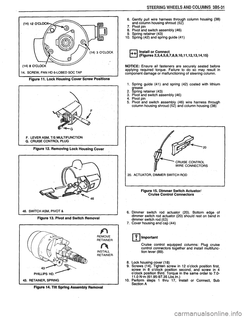
Figure 11. Lock Housing Cover Screw Positions
F. LEVER ASM, TIS MULTIFUNCTION
Figure 12. Removing Lock Housing Cover
6. Gently pull wire harness through column housing (38)
and column housing shroud (62)
7. Pivot pin
8. Pivot and switch assembly (46)
9. Spring retainer (43)
10. Spring (42) and spring guide
(41)
Install or Connect
(Figures 2,3,4,5,6,7,8,9,10,11,12,13,14,15)
NOTICE: Ensure all fasteners are securely seated before
applying required torque. Failure to do so may result in
component damage or malfunctioning of steering column.
1. Spring guide (41) and spring (42) coated with lithium
rease
2. gpring retainer (43)
3. Pivot and switch assembly (46) 4. Pivot pin 5. Pivot and switch assembly (46) wire harness through
column housing shroud (62) and column housing (38)
CRUISE CONTROL WIRE CONNECTORS
6. Dimmer switch rod actuator (20). Bottom edge of
dimmer switch rod actuator (20) should rest on bend in
dimmer switch rod (63)
7. Cover housing end cap (44)
1 43. RETAINER, SPRING REMOVE
RETAINER
INSTALL
RETAINER.
Figure 14. Tlit Sprlng Aswmbly ~emovel
Cruise control equipped columns: Plug cruise
control connectors together and install multifunc-
tion lever (89).
8. Lock housing cover (1
8) 9. Screws (14). Tighten screw in 12 o'clock position first,
screw in 8 o'clock position second, and screw in 4
o'clock position third. Torque in the same order to
7.0- 11 .O N.m (61.95-97.35 Lbs.ln.) 10. Periorrn steps 1 thru 17, Install or Connect, Sub
Section A
Page 183 of 1825
3B5-32 STEERING WHEELS AND COLUMNS
SUB SECTION C
INCLUDES: COLUMN HOUSING, LOCK SHOES, AC-
TUATOR SECTOR ASSEMBLY, SWITCH ACTUATOR
RACK, BEARINGS, AND LOCK BOLT ASSEMBLY
Tools Rsqulrd: J 23653-A Lock Plate Compressor J 35689-A Terminal Remover J 21854-01 Pivot Pin Remover
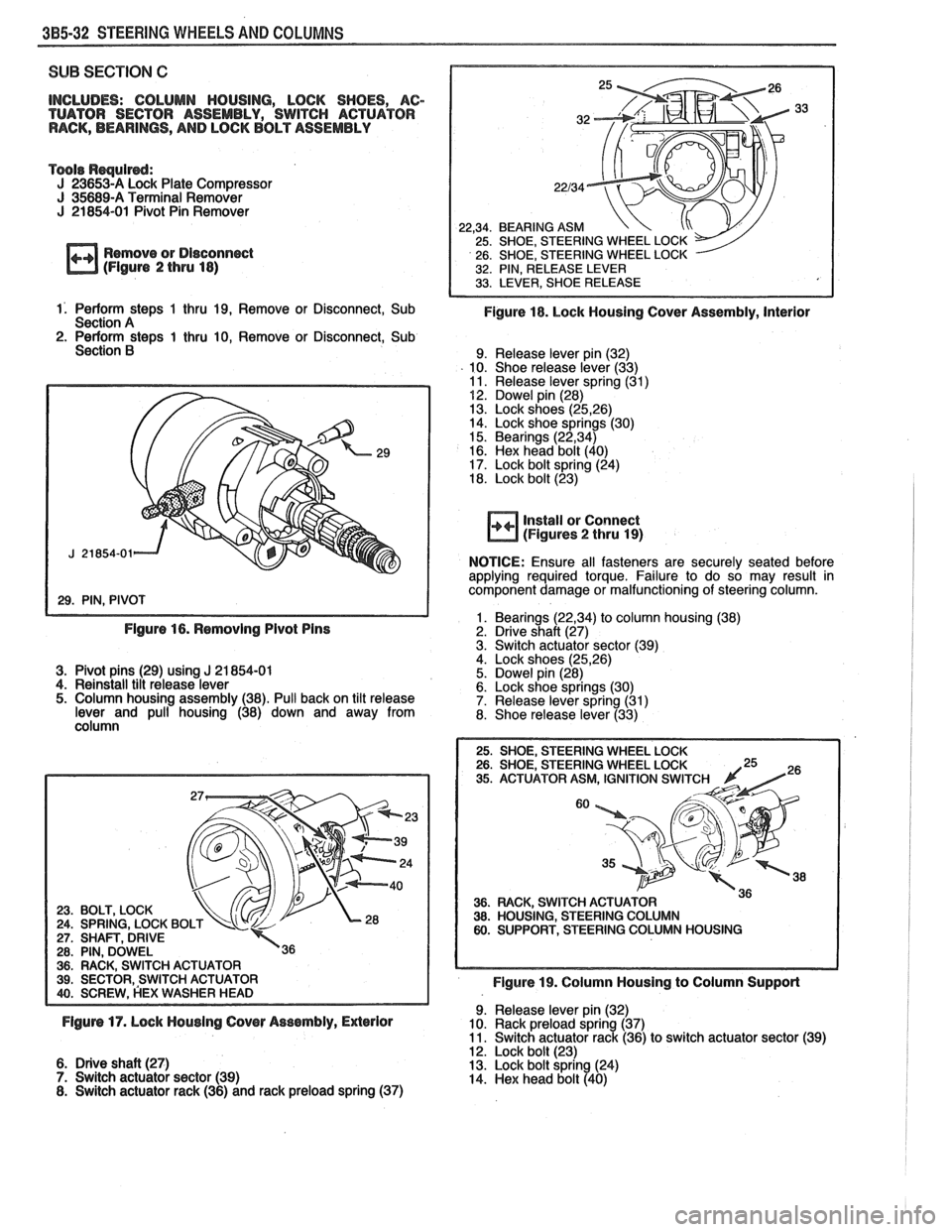
Remove or Disconn~t (Flgure 2 thru 18)
22,34. BEARING ASM 25. SHOE, STEERING WHEEL LOCK
26. SHOE, STEERING WHEEL LOCK
32. PIN, RELEASE LEVER
1. Perform steps 1 thru 19, Remove or Disconnect, Sub Figure 18. Lock Housing Cover Assembly, Interior Section A 2. Perform steps 1 thru 10, Remove or Disconnect, Sub
Section B 9. Release lever pin (32)
10. Shoe release lever (33)
11. Release lever spring (31)
52. Dowel pin (28)
13. Lock shoes (25,26) 14. Lock shoe springs (30)
15. Bearings (22,34) 16. Hex head bolt (40)
17. Lock bolt spring (24)
18. Lock bolt (23)
install or Connect (Figures 2 thru 19)
NOTICE:
Ensure all fasteners are securely seated before
applying required torque. Failure to do so may result in
component damage or malfunctioning of steering column.
1. Bearings
(22,34) to column housing (38) Figure 16. Removing Pivot Pins 2. Drive shaft (27)
3. Switch actuator sector (39) . , 4. Lock shoes (25,26) 3. Pivot pins (29) using J 21 854-01 5. Dowel pin (28)
4. Reinstall tilt release lever
6. Lock shoe springs (30)
5. Column housing assembly (38). Pull back on tilt release
7. Release lever spring (31)
lever and pull housing (38) down and away from 8. Shoe release lever
(33) \, column
VEERING WHEEL LOCK ATOR ASM, IGNITION SWlT
36. FIACK, SWITCH ACTU 38. HOUSING, STEERING 60. SUPPORT, STEERING
Figure 19. Column Housing to Column Support
9. Release lever pin (32) Figurs 17. Lock Housing Cover Assembly, ExPerior 10. Rack preload spring (37)
11. Switch actuator rack (36) to switch actuator sector (39) . , 12. Lock bolt (23)
6. Drive shaft (27)
13. Lock bolt spring (24)
7. Switch actuator sector (39)
14.
Hex head bolt (4Q)
8. Switch actuator rack (36) and rack preload spring (37)
Page 185 of 1825
385.34 STEERING WHEELS AND COLUMNS
9. Shaft assembly (55-58)
10. Lower shaft 58)
11. Sphere (56)
I rom upper shaft (55) . 12. Preload spring (57) from sphere (56)
13. Screws (59)
14. Housing support assembly (60) and dimmer switch rod
(63) 15. h& nut (65) and hex head bolt
16. Dimmer switch (64)
17. Mounting stud 18. Shroud, column housing (62)
Insbll or Connect (Flgure 2 thru 26)
WTICE: Ensure all fasteners are securely seated before
applying required torque. Failure to do so may result in
component damage or malfunctioning of steering column.
Column housing shroud (62) to jacket (66)
Dimmer switch rod (63) to housing support (60)
Housing support assembly (60) and screws (59) and
torque to 5.5-12.0
N.m (48.68-106.2 Lbs.ln.) Actuator rod assembly (35) to track in housing support
(60)
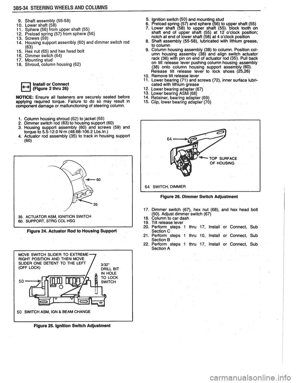
35. ACTUATOR ASM, IGNITION SWITCH 60. SUPPORT, STRG COL HSG I
Figure 24. Actuator Rod to Housing Supporl
50 SWITCH ASM, IGN & BEAM CHANGE
5. Ignition switch (50) and mounting stud
6. Preload sprin (57) and sphere (56) to upper shaft (55)
7. Lower shaft
a58) to upper shaft (55). block tooth on
shaft end of upper shaft (55) at 12 o'clock position;
notch at end of lower shaft (58) at 4 o'clock position
8. Shaft assembly
(55-58), lubricated with lithium grease,
to column
9. Column housing assembly (38) to column. Position col-
umn housing assemby (38) and align switch actuator
rack (36) with pin on end of actuator rod (35). Pull back
on tilt release lever pushing column housing assembly
(38) onto column housing support assembly (60).
Release tilt release lever to lock shoes
(2526) 10. Remove tilt release lever 11. Lower bearing (71) and screws (72), inner surface lubri-
cated with lithium grease
12. Lower bearing adapter (67)
13. Lower bearing ASM (68)
14. Retainer, bearing adapter
(69) 15. Clip, lower bearing adapter (70)
TOP SURFACE
OF HOUSING
Figure 26. Dimmer Switch Adjustment
17. Dimmer switch
(67), hex nut (68), and hex head bolt
(50). Adjust dimmer switch (67)
18. Column to car dash
19. Tilt release lever
20. Perform
stem 1 thru 17. Install or Connect. Sub
Section C ' 21. Perform steps 1 thru 10, Install or Connect, Sub
Section B 22. .Perform steps 1 thru 17, Install or Connect, Sub
Section A
Flguro 25. lgnltion Switch Adjustment