1988 PONTIAC FIERO engine coolant
[x] Cancel search: engine coolantPage 433 of 1825

6C-2 ENGINE FUEL
components such as the accelerator pumps and/or
air-fuel mixture leaning effects.
Various types and concentrations of alcohols are
used in commercial gasoline. Some alcohols are more
detrimental to fuel system components than others. If
an excessive amount of alcohol in the fuel is suspected
as the cause of a driveability condition, the following
procedure may be used to detect the presence of
alcohol in the fuel.
In this procedure, water is used to
extract the alcohol from the fuel. However, the specific
type of alcohol is not determined.
The fuel sample should be drawn from the
bottom part of the tank so that any water, if already
present, can be detected. The sample should be bright
and clear. If the sample appears cloudy or
contaminated with water as indicated by a water layer
in the bottom part of the sample, this procedure should
not be used. The fuel system should then be cleaned
(See Fuel System Cleaning).
Testing Procedure
1. Using a 100 ml cylinder with 1 ml graduation
marks, fill with fuel to the 90 ml mark.
2. Add 10 ml of water to bring the total fluid volume
to 100 ml and install a stopper.
3. Shake vigorously for 10 to 15 seconds.
4. Carefully loosen stopper to release pressure.
5. Close the stopper and shake vigorously again for
10 to 15 seconds.
6. Carefully loosen
stopper to release pressure.
7. Put the graduated cylinder on a level surface for
approximately 5 minutes to allow adequate liquid
separation.
If alcohol is present in the fuel, the volume of the
lower layer, which would now contain alcohol and
water will be greater than 10 ml. For example, if the
volume of the lower layer is increased to 15 ml, it
would indicate at least 5 percent alcohol in fuel. The
actual amount of alcohol may be somewhat greater
because this procedure does not extract all of the
alcohol from the fuel.
FUEL METERING
Throttle Body lnjection
(TBI)
With Throttle Body Injection (TBI), an injection
unit is placed on the intake manifold where the
carburetor is normally mounted. The TBI unit is
computer controlled and supplies the correct amount
of fuel during all engine operating conditions. See
Section 6E2 for information relative to operation and
diagnosis of TBI units.
Port Fuel lnjection
The ECM is in complete control of this fuel
delivery system during all driving conditions.
The intake manifold is used only to let air into the
engine. Fuel is injected by separate injectors that are
mounted over the intake valve.
With the Port Injection System, there is no need
for a Thermac, EFE, Map Sensor, Baro Sensor, A.I.R.
System, or Dual Bed Converter. This
system provides better cold driveability,
lower exhaust emissions and better throttle response.
In Sequential Fuel Injection systems (SFI),
injectors turn on at every crankshaft revolution. The
ECM controls the injector "on" time so that the
correct amount of fuel is metered, depending on
driving conditions.
Two interchangeable
"0" rings are used on the
injector that must be inspected when the injectors are
removed. Check
"0" rings for cuts or other type of
damage and replace as necessary.
The air cleaner is remotely mounted near the
radiator. It is connected to the intake manifold by air
intake ducting.
Also, mounted between the air cleaner and
intake, are the mass air flow sensor and throttle body.
Cold driveability characteristics are greatly
improved with the aid of an engine coolant supply to
the throttle body for rapid warm up.
The throttle body design uses an integral Idle Air
Control to govern idle speed and a Throttle Position
Sensor (TPS). The IAC and TPS are both controlled
by the ECM.
A large diameter fuel rail is attached to the intake
manifold and supplies fuel to all the injectors.
A fuel pressure tap is located on the rail for quick
pressure checks.
Fuel is recirculated through the rail continually
while the engine is running. This removes air and
vapors from the fuel as well as keeping the fuel cool
during hot weather operation.
A fuel pressure regulator is mounted on the fuel
rail. It maintains a constant 36 psi pressure across the
injectors under all operating conditions. It is
accomplished by controlling the amount of fuel that is
recirculated back to the fuel tank, based on engine
demand.
The pressure regulator also uses an
"0" ring for
attachment. The
"0" ring used is the same one that is
used for the injectors.
Some engines also have an accumulator that is
located in the fuel feed line near the cowl area. It is used
to dampen the vibration that is caused by the
pressurized fuel and the pulsing of the injector.
See Section 6E3 for more information and
diagnosis.
Fuel Feed and Return Pipe
When replacing fuel feed and return pipes, always
replace them with welded steel tubing meeting GM
Specification
124M, or its equivalent. The replacement
pipe must use the same type of fittings as the original
pipes to ensure the integrity of the connection.
NOTICE: Do not replace fuel pipe with fuel hose
or any other type of tubing such as copper or
aluminum. Only tubing meeting the 124M
specification is capable of meeting all the pressure
and vibration characteristics necessary to ensure
the durability standard required.
Always check and replace any
"0" rings or
washers that appear damaged.
Page 486 of 1825
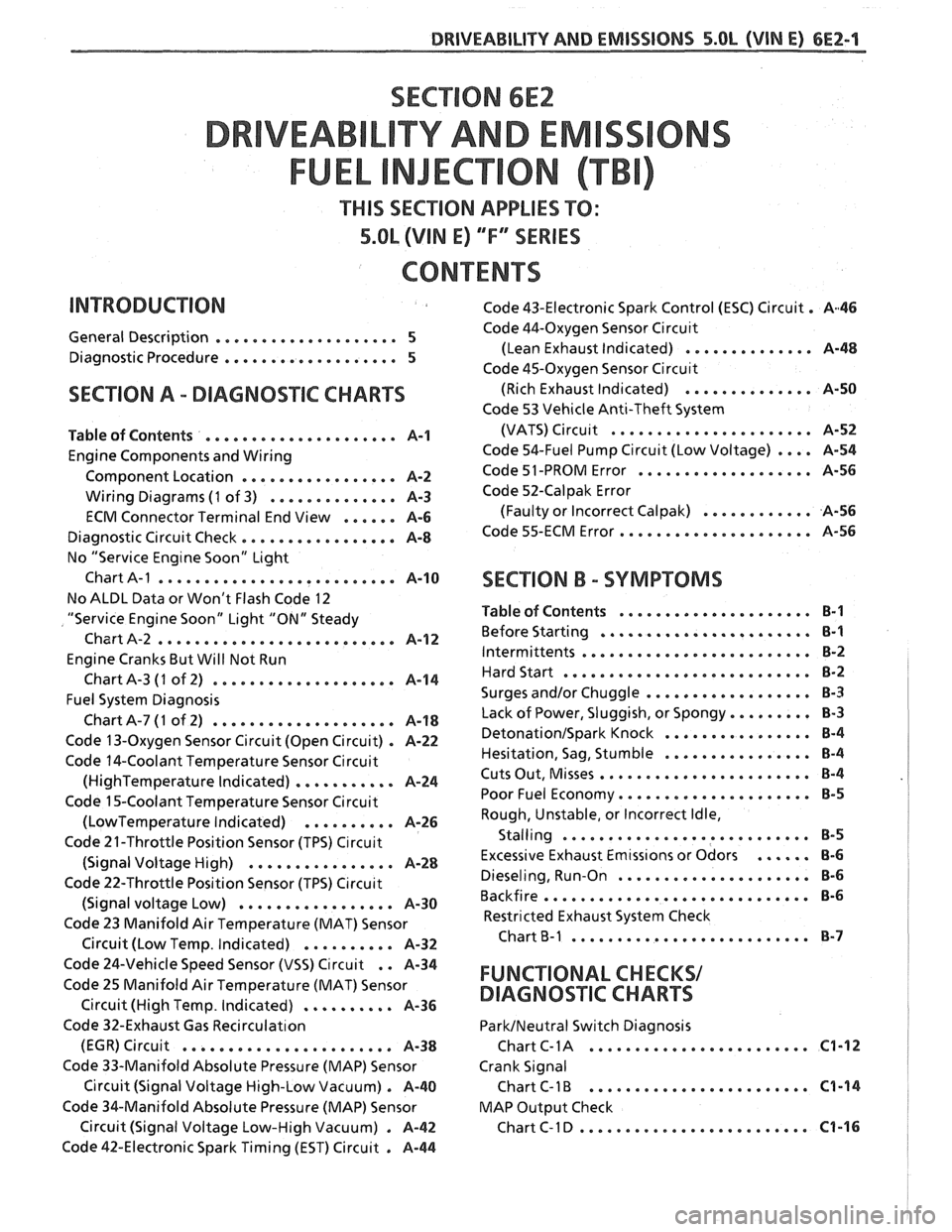
SECTION 6E2
TY AND EM
THIS SECTION APPLIES TO:
5.OL (VIN E) ""FYSERIES
CONTENTS
General Description .................... 5
Diagnostic Procedure ................... 5
SECTION A . DIAGNOSIIC CHARTS
Table of Contents ..................... A-1
Engine Components and Wiring
Component Location
................. A-2
Wiring Diagrams (1 of 3) .............. A-3
ECM Connector Terminal End View ...... A-6
Diagnostic Circuit Check ................. A-8
No "Service Eng~ne Soon" Light
Chart
A-1 .......................... A-10
No ALDL Data or Won't Flash Code 12
"Service Engine Soon" Light "ON" Steady
Chart A-2
.......................... A-1 2
Engine Cranks But Will Not Run
ChartA-3
(1 of 2) .................... A-14
Fuel System Diagnosis
ChartA-7(1 of 2) .................... A-18
Code 13-Oxygen Sensor Circuit (Open Circuit) . A-22
Code 14-Coolant Temperature Sensor Circuit
(HighTemperature Indicated) ........... A-24
Code 15-Coolant Temperature Sensor Circuit
(LowTemperature Indicated) .......... A-26
Code 21-Throttle Position Sensor (TPS) C~rcuit
(Signal Voltage High) ................ A-28
Code 22-Throttle Position Sensor (TPS) C~rcuit
(Signal voltage Low) ................. A-30
Code 23 Manifold Air Temperature (MAT) Sensor
. Circuit (Low Temp Indicated) .......... A-32
Code 43-Electronic Spark Control (ESC) Circuit . A46
Code 44-Oxygen Sensor Circu~t
(Lean Exhaust Indicated) .............. A-48
Code 45-Oxygen Sensor Circu~t
(Rich Exhaust Indicated) .............. A-50
Code 53 Vehicle Anti-Theft System
(VATS)
Circu~t ...................... A-52
Code 54-Fuel Pump Circuit (Low Voltage) .... A-54
Code 51 -PROM Error ................... A-56
Code 52-Calpak Error
(Faulty or Incorrect
Calpak) ............ A-56
Code 55-ECM Error ..................... A-56
SECTION B . SYMPTOMS
Table of Contents ..................... B-1
Before Starting ....................... B-1
Intermittents ......................... B-2
Hard Start ........................... 8-2
.................. Surges and/or Chuggle B-3
Lack of Power. Sluggish. or Spongy ......... 8-3
DetonationISpark Knock ................ 8-4
................ Hesitation. Sag. Stumble B-4
Cuts Out. Misses ....................... B-4
Poor Fuel Economy ..................... B-5
Rough. Unstable. or Incorrect Idle.
. Stalling ....................... ... B-5
Excessive Exhaust Emtss~ons or Odors ...... 8-6
Dieseling. Run-on ..................... 8-6
Backfire ............................. B-6
Restricted Exhaust System Check
Chart
B-1 .......................... 8-7
Code 24-Vehicle Speed Sensor (VSS) Circuit . . A-34
Code 25 Manifold Air Temperature (MAT) Sensor FUNCTIONAL CHECKS/
Circuit (High Temp . Indicated) .......... A-36 DIAGNOSqIC CHARTS
Code 32-Exhaust Gas Recirculat~on ParkINeutral Switch Diagnosis
........................ (EGR) Circuit ....................... A-38 Chart C- 1 A C1-12
Code 33-Manifold Absolute Pressure (MAP) Sensor Crank Signal
Circuit (Signal Voltage High-Low Vacuum)
. A-40 Chart C-1 B ........................ C1-14
Code %&Manifold Absolute Pressure (MAP) Sensor MAP
Output Check
......................... Circuit (Signal Voltage Low-High Vacuum) . A-42 ChartC-ID C1-16
Code 42-Electronic Spark Timing (EST) Circuit . A-44
Page 487 of 1825
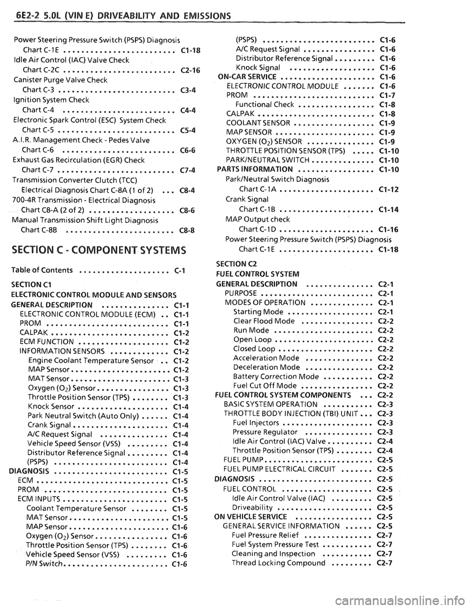
6E2-2 5.OL (VIN El DRlVEABlLlTV AND EMISSIONS
Power Steering Pressure Switch (PSPS) Diagnosis
Chart C-1
E ......................... C1-18
ldle Air Control (IAC) Valve Check
Chart C-2C
......................... C2-16
Canister Purge Valve Check
Chart C-3
.......................... C3-4
Ignition System Check
Chart C-4
......................... C4-4
Electronic Spark Control (ESC) System Check
Chart C-5
.......................... C5-4
A.I.R. Management Check . Pedes Valve
Chart C-6
......................... C6-6
Exhaust Gas Recirculation (EGR) Check
Chart C-7
.......................... C7-4
Transmission Converter Clutch (TCC)
Electrical Diagnosis Chart C-8A
(1 of 2) ... C8-4
700-4R Transmission . Electrical Diagnosis
Chart C8-A
(2 of 2) ................... C8-6
Manual Transmission Shift Light Diagnosis
Chart
C-8B ........................ C8-8
SECTION C . COMPONENT SYSTEMS
Table of Contents .................... C-1
SECTION
C1
ELECTRONIC CONTROL MODULE AND SENSORS
GENERAL DESCRIPTION
............... C1-1
ELECTRONIC CONTROL MODULE (ECM) . . C1-1
PROM ........................... C1-1
CALPAK .......................... C1-2
ECMFUNCTION .................... C1-2
INFORMATION SENSORS ............. C1-2
Engine Coolant Temperature Sensor . . C1-2
MAP Sensor ...................... C1-2
MAT Sensor ...................... C1-3
Oxygen (Oz) Sensor ................ C1-3
Throttle Position Sensor (TPS) ........ C1-3
Knock Sensor .................... C1-4
Park Neutral Switch (Auto Only) ...... C1-4
Crank Signal ..................... C1-4
A/C Request Signal ............... C1-4
Vehicle Speed Sensor (VSS) ......... C1-4
Distributor Reference Signal ......... C1-4
(PSPS) ......................... C1-4
DIAGNOSIS ......................... C1-5
ECM ............................. C1-5
PROM ........................... C1-5
ECMINPUTS ....................... C1-5
Coolant Temperature Sensor ........ C1-5
MAT Sensor ...................... C1-5
MAP Sensor ...................... C1-6
Oxygen (Oz) Sensor ................ C1-6
Throttle Position Sensor (TPS) ........ C1-6
Vehicle Speed Sensor (VSS) ......... C1-6
P/N Switch ....................... C1-6
(PSPS) ......................... C1-6
A/C Request Signal ................ C1-6
......... Distributor Reference Signal C1-6
Knock Signal ................... C1-6
..................... ON-CARSERVICE C1-6
....... ELECTRONIC CONTROL MODULE C1-6
........................... PROM C1-7
Functional Check ................. C1-8
.......................... CALPAK C1-8
.................. COOLANTSENSOR C1-9
MAPSENSOR e..................... C1-9
OXYGEN (02) SENSOR ............... C1-9
THROTTLE POSITION SENSOR (TPS) ..... C1-10
PARKINEUTRAL SWITCH .............. C1-10
PARTS INFORMATION ................. C1-10
ParklNeutral Switch Diagnosis
Chart
C-1A ..................... C1-12
Crank Signal
Chart
C-1B ..................... C1-14
MAP Output check
Chart C-1 D
..................... C1-16
Power Steering Pressure Switch (PSPS) Diagnosis
ChartC-lE ..................... C1-18
SECTION C2
FUEL CONTROL SYSTEM
GENERAL DESCRIPTION
............... C2-1
PURPOSE ...*..................... C2-1
MODES OF OPERATION .............. C2-1
Starting Mode ................... C2-1
Clear Flood Mode ................ C2-2
RunMode ...................... C2-2
Open Loop ...................... C2-2
Closed Loop ..................... C2-2
Acceleration Mode ............... C2-2
Deceleration Mode ............... C2-2
Battery Correction Mode ........... C2-2
Fuel Cut Off Mode ................ C2-2
... FUEL CONTROL SYSTEM COMPONENTS C2-2
BASIC SYSTEM OPERATION ........... C2-3
THROTTLE BODY INJECTION (TBI) UNIT ... C2-3
Fuel Injectors .................... C2-3
Pressure Regulator ............... C2-3
.......... Idle Air Control (IAC) Valve C2-4
........ Throttle Position Sensor (TPS) C2-4
FUELPUMP ........................ C2-5
....... FUEL PUMP ELECTRICAL CIRCUIT C2-5
DIAGNOSIS
......................... C2-5
FUEL CONTROL .................... C2-5
......... Idle Air Control Valve (IAC) C2-5
Dr~veability ..................... C2-5
ON VEHICLE SERVICE
................. C2-5
...... GENERALSERVICE INFORMATION C2-5
Fuel Pressure Relief ............... C2-7
........... Fuel System Pressure Test C2-7
Cleaning and lnspect~on ........... C2-7
......... Thread Lockrng Compound C2-7
Page 492 of 1825
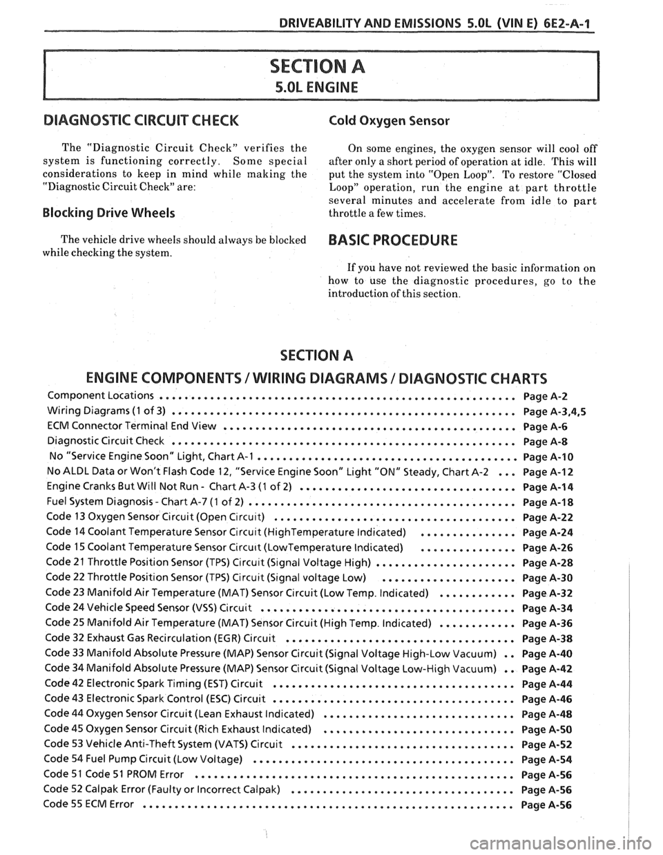
DRIVEABILITY AND EMISSIONS S.OL (VIN E) 6EZ-A-1
5.OL ENGINE
DIAGNOS"FC CIRCUIT CHECK Cold Oxygen Sensor
The "Diagnostic Circuit Check" verifies the On some engines. the oxygen sensor will cool off
system is functioning correctly
. Some special after only a short period of operation at idle . This will
considerations to keep in mind while making the
put the system into "Open Loop"
. To restore "Closed
"Diagnostic Circuit Check" are:
Loop" operation. run the engine at part throttle
several minutes and accelerate from idle to part
Blocking Drive Wheels throttle a few times .
The vehicle drive wheels should always be blocked BASIC PROCEDURE
while checking the system .
If you have not reviewed the basic information on
how to use the diagnostic procedures. go to the
introduction of this section
.
SECTION A
ENGINE COMPONENTS
/ WlRlNG DIAGRAMS 1 DIAGNOSTIC CHARTS
Component Locations ........................................................ Page A-2
Wiring Diagrams (1 of 3) ...................................................... Page A.3.4.5
ECM Connector Terminal End View .............................................. Page A-6
Diagnostic Circuit Check ...................................................... Page A-8
No "Service Engine Soon" Light. Chart A-1 ......................................... Page 14-10
No ALDL Data or Won't Flash Code 12. "Service Engine Soon" Light "ON" Steady. Chart A-2 ... Page A-I 2
Engine Cranks But Will Not Run . Chart A-3 (1 of 2) .................................. Page A-1 4
. Fuel System Diagnosis Chart A-7 (1 of 2) .......................................... Page A-1 8
Code 13 Oxygen Sensor Circuit (Open C~rcu~t) ...................................... Page A-22
Code 14 Coolant Temperature Sensor Circu~t (HighTemperature Indicated) ............... Page A-24
Code 15 Coolant Temperature Sensor Circu~t (LowTemperature Indicated) ............... Page A-26
Code 21 Throttle Position Sensor (TPS) Circu~t (S~gnal Voltage High) ...................... Page A-28
Code 22 Throttle Position Sensor (TPS) Circuit (Signal voltage Low) ..................... Page A-30
Code 23 Manifold Air Temperature (MAT) Sensor Circuit (Low Temp . Indicated) ............ Page A-32
Code 24 Vehicle Speed Sensor (VSS) Circuit ........................................ Page A-34
Code 25 Manifold Air Temperature (MAT) Sensor Circuit (High Temp . Indicated) ............ Page A-36
Code 32 Exhaust Gas Recirculation (EGR) Circuit .................................... Page A-38
Code 33 Manifold Absolute Pressure (MAP) Sensor Circuit (Signal Voltage High-Low Vacuum) . . Page A-40
Code 34 Manifold Absolute Pressure (MAP) Sensor Circuit (Signal Voltage Low-High Vacuum) . . Page A-42
Code 42 Electronic Spark Timing (EST) Circuit ...................................... Page A-44
Code 43 Electronic Spark Control (ESC) Circuit ...................................... Page A-46
Code 44 Oxygen Sensor Circuit (Lean Exhaust Indicated) .............................. Page A-48
Code 45 Oxygen Sensor Circuit (Rich Exhaust Indicated) .............................. Page A-50
Code 53 Vehicle Anti-Theft System (VATS) Circuit ................................... Page A-52
Code 54 Fuel Pump Circuit (Low Voltage) ......................................... Page A-54
Code 51 Code 51 PROM Error .................................................. Page A-56
Code 52 Calpak Error (Faulty or Incorrect Calpak) ................................... Page A-56
.......................................................... Code55ECMError PageA-56
Page 493 of 1825
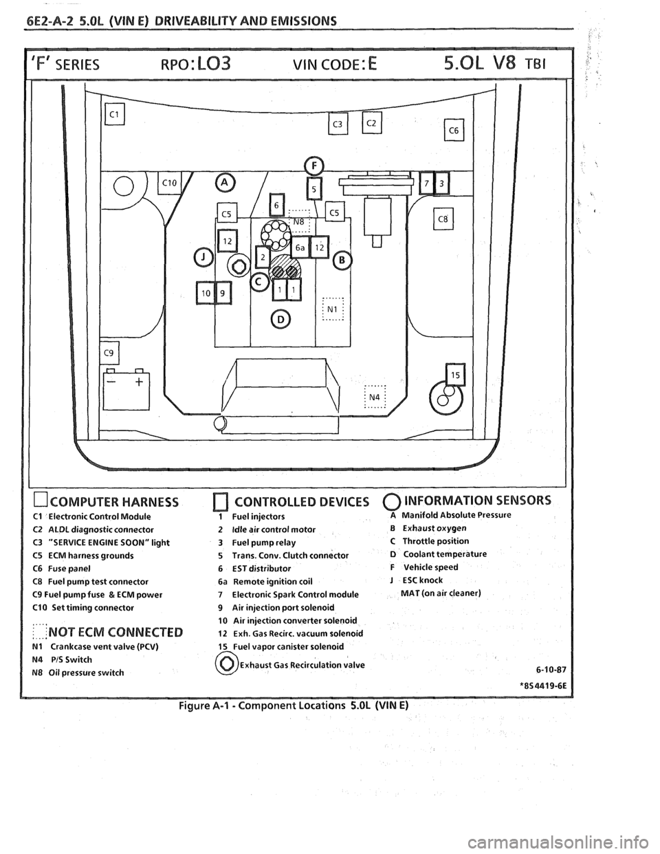
6E2-A-2 5.OL (VIN E) DRIVEABILIW AND EMISSIONS
IFf SERIES VIN CODE: E
OCOMPUTER HARNESS
C1 Electronic Control Module
C2 ALDL diagnostic connector
C3 "SERVICE ENGINE SOON" light
C5 ECM harness grounds
C6 Fuse panel
C8 Fuel pump test connector
C9 Fuel pump fuse & ECM power
C10 Set timing connector
....,
: . ... 'NOT ECM CONNECTED
N1 Crankcase vent valve (PCV)
N4 PIS Switch
N8 Oil pressure switch
[7 CONTROLLED DEVICES 0 INFORMATION SENSORS
1 Fuel injectors A Manifold Absolute Pressure
2 Idle air control motor B Exhaust oxygen
3 Fuel pump relay
C Throttle position
5 Trans. Conv. Clutch connector
D Coolant temperature
6 EST distributor
F Vehicle speed
6a Remote ignition coil
J ESCknock
7 Electronic Spark Control module MAT (on air cleaner)
9 Air injection port solenoid
10 Air injection converter solenoid
12 Exh. Gas Recirc. vacuum solenoid
15 Fuel vapor canister solenoid
Exhaust Gas Recirculation valve
6-1
0-87
Figure A-I - Component Locations 5.OL (VIN E)
Page 499 of 1825
6E2-A-8 S.OL (VIN E) DRIVEABILITY AND EMISSIONS
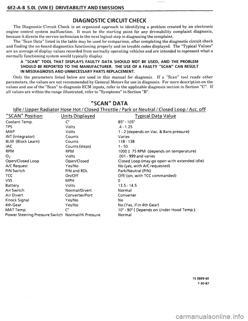
DIAGNOSmIC CIRCUIT CHECK
The Diagnostic Circuit Check is an organized approach to identifying a problem created by an electronic
engine control system malfunction. It must be the starting point for any driveability complaint diagnosis,
because it directs the service technician to the next logical step in diagnosing the complaint.
The "Scan Data" listed in the table may be used for comparison, after completing the diagnostic circuit check
and finding the on-board diagnostics functioning properly and no trouble codes displayed. The "Typical Values"
are an average of display values recorded from normally operating vehicles and are intended to represent what a
normally functioning system would typically display.
A "SCAN" TOOL THAT DISPLAYS FAULTY DATA SHOULD NOT BE USED, AND THE PROBLEM
SHOULD BE REPORTED TO THE MANUFACTURER. THE USE OF A FAULTY "SCAN" CAN RESULT
IN MISDIAGNOSIS AND UNNECESSARY PARTS REPLACEMENT.
Only the parameters listed below are used in this manual for diagnosis. If
a "Scan" tool reads other
parameters, the values are not recommended by General Motors for use in diagnosis. For more description on the
values and use of the "Scan" to diagnosis ECM inputs, refer to the applicable diagnosis section in Section
"C". If
all values are within the range illustrated, refer to "Symptoms" in Section
"B".
""SCAN" DATA
Idle / Upper Radiator Hose Hot / Closed Throttle / Park or Neutral /Closed Loop / Acc. off
"SCAN" Position Units Displayed Typical
Data Value
Coolant Temp. CO 85" - 105"
TPS Volts .4 - 1.25
MAP Volts
1 - 2 (depends on Vac. & Baro pressure)
INT (Integrator) Counts Varies
BLM (Block Learn) Counts 118- 138
IAC Counts (steps) 1-50
RPM RPM 1000
k 75 RPM (depends on temperature)
0 2 Volts .001 - 999 and varies
OpenIClosed Loop OpenICIosed Closed Loop (may go open with extended idle)
A/C Request YesINo No (yes, with A/C requested)
PIN Switch PIN and RDL
ParkINeutral (PIN)
TCC
On/Off Off1 (on, with TCC commanded)
VSS MPH 0
Battery Volts 13.5- 14.5
Air Switch NormalIDivert Normal
Air Divert ConverterIPort Converter
Knock Signal
YesINo N o
4th Gear
YesINo No (Yes, if in 4th Gear)
MAT Temp.
CO 10" - 90" ( Depends on Under Hood Temp.).
Power Steering Pressure Switch
NormalIHi Pressure Normal
Page 515 of 1825
bE2-A-24 S.OL (VIN E) DRIVEABILITY AND EMlSSlONS
SENSOR GND
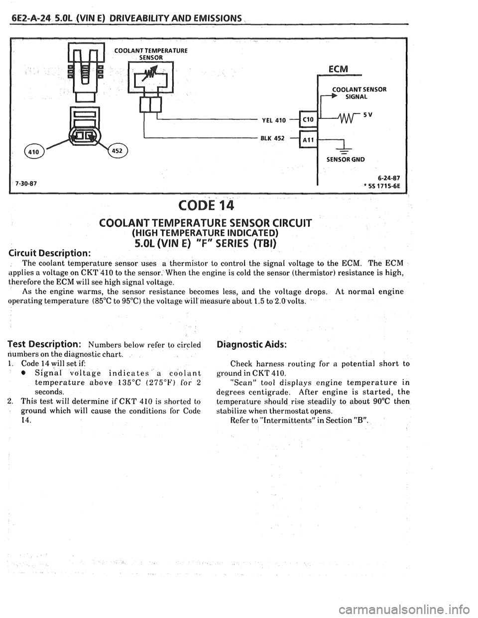
COD^ 14
COOLANT TEMPERATURE SENSOR CIRCUIT
(HIGH TEMPERATURE INDICATED)
5.OL (VIN E) "F"" SERIES (TBI)
Circuit Description:
The coolant temperature sensor uses a
thermistor to control the signal voltage to the ECM. The ECM
applies a voltage on CKT4410 to the sensor. When the engine is cold the sensor (thermistor) resistance is high,
therefore the
ECM will see high signal voltage.
As the engine warms, the sensor resistance becomes less, and the voltage drops. At normal engine
operating temperature
(85°C to 95OC) the voltage will'measure about 1.5 to 2.0 volts.
Test Description: Numbers below refer to circled
numbers on the diagnostic chart.
1. Code 14 will set if:
s Signal voltage indicates a coolant
temperature above
135°C (275°F) for 2
seconds.
2. This test will determine if CKT 410 is shorted to
ground which will cause the conditions for Code
14.
Diagnostic Aids:
Check harness routing for a potential short to
ground in CKT
41 0.
"Scan" tool displays engine temperature in
degrees centigrade. After
engine is started, the
temperature should rise steadily to about
90°C then
stabilize when thermostat opens.
Refer to "Intermittents" in Section
"B".
Page 517 of 1825
6EZ-A-26 5.8L (VIN E) DRIVEABILITY AND EMISSIONS
OLANT SENSOR
SENSOR GND
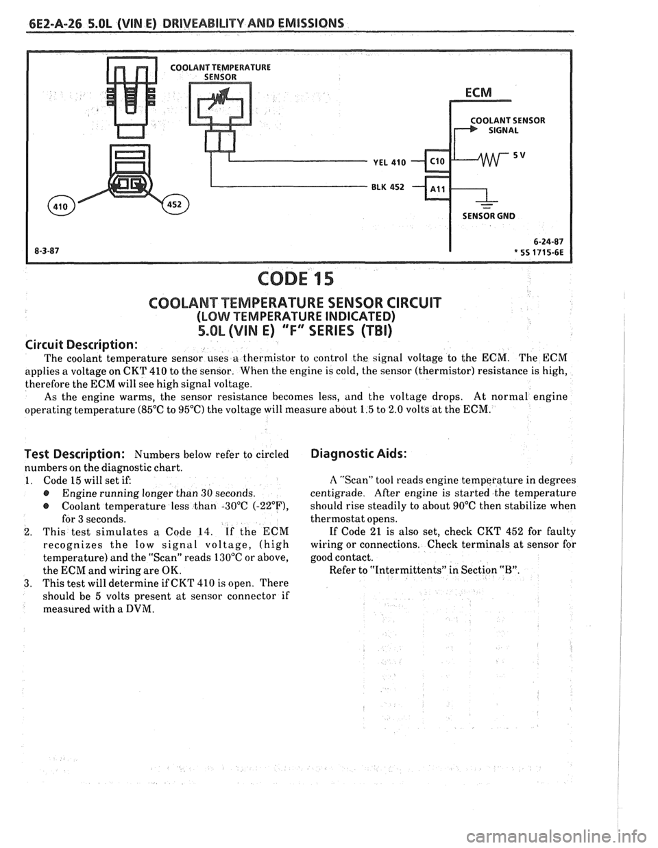
CODE 15
Test Description: Numbers below refer to circled
numbers on the diagnostic chart.
1. Code 15 will set if:
@ Engine running longer than 30 seconds.
@ Coolant temperature less than -30°C (-22"F),
for 3 seconds.
2. This test simulates a Code 14. If the ECM
recognizes the
low signal voltage, (high
temperature) and the "Scan" reads 130°C or above,
the ECM and wiring are OK.
3. This test will determine if CKT 410 is open. There
should be 5 volts present at sensor connector if
measured with a
DVM.
COOLANT TEMPERATURE SENSOR CIRCUIT
(LOMI TEMPERATURE INDICATED)
5.OL (VIM E) ""FYERIES (TBI)
Diagnostic Aids:
Circuit
Description:
The coolant temperature sensor uses a thermistor to control the signal voltage to the ECM. The ECM
applies a voltage on CKT 410 to the sensor. When the engine is cold, the sensor (thermistor) resistance is high,
therefore the ECM will see high signal voltage.
As the engine warms, the sensor resistance becomes less, and the voltage drops. At
normal engine
operating temperature (85°C to 95°C) the voltage will measure about 1.5 to 2.0 volts at the ECM.
A "Scan" tool reads engine temperature in degrees
centigrade. After engine is started the temperature
should rise steadily to about 90°C then stabilize when
thermostat opens.
If Code 21 is also set, check CKT 452 for faulty
wiring or connections. Check terminals at sensor for
good contact.
Refer to "Intermittents" in Section
"B".
~