1988 PONTIAC FIERO relay
[x] Cancel search: relayPage 529 of 1825
6EZ-A-38 5.OL (VIN E) DRIVEABILITY AND EMISSIONS
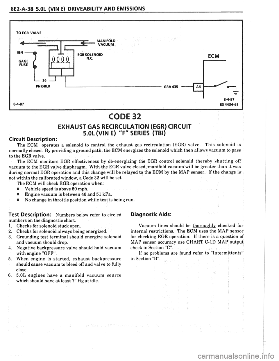
TO EGR VALVE
CODE 32
EXHAUSWAS RECIRCULATION (EGR) CIRCUIT
5.OL (VIN E) "FF" SERIES (TBI)
Circuit Description:
The ECM operates a solenoid to
control the exhaust gas recirculation (EGR) valve. This solenoid is
normally closed. By providing a ground path, the ECM energizes the solenoid which then allows vacuum to pass
to the EGR valve.
The ECM monitors EGR effectiveness by de-energizing the EGR control solenoid thereby shutting off
vacuum to the EGR valve diaphragm. With the EGR valve closed, manifold vacuum will be greater than it was
during normal EGR operation and this change will be relayed to the ECM by the MAP sensor. If the change is
not within the calibrated window, a Code
32 will be set.
The ECM will check EGR operation when:
@ Vehicle speed is above 50 mph.
@ Engine vacuum is between 40 and 51 kPa.
@ No change in throttle position while test is being run.
Test Description: Numbers below refer to circled
numbers on the diagnostic chart.
1. Checks for solenoid stuck open.
2. Checks for solenoid always being energized.
3. Grounding test terminal should energize solenoid
and vacuum should drop.
4. Negative backpressure valve should hold vacuum
with engine "OFF".
5. When engine is started, exhaust backpressure
should cause vacuum to bleed off and valve to fully
close.
6. 5.OL engines have a ~nanifold vacuum source
which should have at least
7" Hg at idle.
Diagnostic Aids:
Vacuum lines should be thoroughly checked for
internal restrictions. The ECM uses the MAP sensor
for checking EGR operation. If there is a question of
MAP sensor accuracy use
CHART C-1D MAP output
check in Section "C".
If no problems are found refer to "Intermittents"
in Section
"13".
Page 545 of 1825
6E2-A-54 5.OL (VIN E) DRIVEABILITY AND EMISSIONS
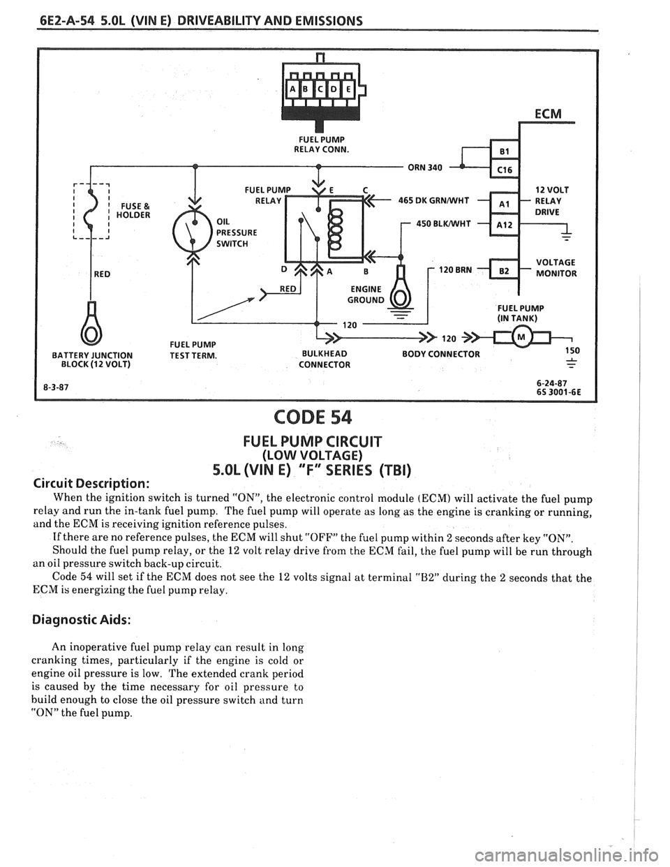
465 DK GRNMlHT
450 BLWHT
FUEL PUMP BATTERY JUNCTION TEST TERM. BULKHEAD BODY CONNECTOR
BLOCK (12 VOLT) CONNECTOR
CODE 54
FUEL PUMP CIRCUIT
(LOW VOLTAGE)
5.OL (VIN E) "F"" SERIES (TBI)
Circuit Description:
When the ignition switch is turned "ON", the electronic control module (ECM) will activate the fuel pump
relay and run the in-tank fuel pump. The fuel pump will operate as long as the engine is cranking or running,
and the ECM is receiving ignition reference pulses.
If there are no reference pulses, the ECM will shut
"OFF" the fuel pump within 2 seconds after key "ON".
Should the fuel pump relay, or the
12 volt relay drive from the ECM fail, the fuel pump will be run through
an oil pressure switch back-up circuit.
Code
54 will set if the ECM does not see the 12 volts signal at terminal "B2" during the 2 seconds that the
ECM is energizing the fuel pump relay.
Diagnostic Aids:
An inoperative fuel pump relay can result in long
cranking times, particularly if the engine is cold or
engine oil pressure is low. The extended crank period
is caused by the time necessary for oil pressure to
build enough to close the oil pressure switch and turn
"ON" the fuel pump.
Page 546 of 1825
DRlVEABlLlTY AND EMISSIONS 5.Ob (VIN E) 6E2-A-5%
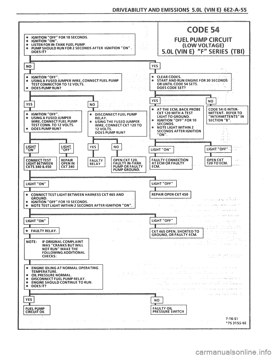
FUEL PUMP CIRCUIT
MPER WIRE, CONNECT FUEL PUMP
TO 12 VOLTS.
CONNECT TEST LIGHT BETWEEN HARNESS
CKT465 AND
EL PUMP RELAY.
Page 549 of 1825
6EZ-B-2 5.OL (VIN E) DRIVEABILITY AND EMISSIONS
Problem may or may not turn "ON" the "Service Engine Soon" light, or store a code.
DO NOT use the trouble code charts in Section
"A" for intermittent problems. The fault must be
present to locate the problem. If a fault is
intermittent, use of trouble code charts may result
in replacement of good parts.
@ Most intermittent problems are caused by faulty
electrical connections or wiring. Perform
careful check of suspect circuits for:
- Poor mating of the connector halves, or
terminals, not fully seated in the connector
body (backed out).
I - Improperly formed or damaged terminals.
All connector terminals in problem circuit
should be carefully reformed to increase
contact tension.
- Poor terminal to wire connection. This
requires removing the terminal from the
connector body to check as outlined in the
Introduction to Section
"6E".
@ If a visual (physical) check does not find the
cause of the problem, the car can be driven with
a voltmeter connected to a suspected circuit or a
"Scan" tool may be used. An abnormal voltage
reading, when the problem occurs, indicates the
problem may be in that circuit. If the wiring
and connectors check OK, and a trouble code was
stored for a circuit having a sensor, except
for Codes 44 and 45, substitute a known good
sensor and recheck.
@ Loss of trouble code memory. To check,
disconnect TPS and idle engine until "Service
Engine Soon" light comes
"ON". Code 22 should
be stored, and kept in memory, when ignition is
turned "OFF" for at least 10 seconds. If not, the
ECM
is faulty.
@ An intermittent "SES" light, and no trouble
codes, may be caused by:
- Electrical system interference caused by a
defective relay, ECM driven solenoid, or switch.
They can cause a sharp electrical surge.
Normally, the problem will occur when the
faulty component is operated.
- Improper installation of electrical options, such
as lights, 2-way radios, etc.
- EST wires should be routed away from spark
plug wires, ignition system components, and
generator. Wire for CKT 453 from ECM to
ignition system should be a good ground.
- Ignition secondary shorted to ground.
- CKTs 419 ("SES" light) or 451 (Diagnostic Test)
intermittently shorted to ground.
- ECM power grounds.
HARD START
Definition: Engine cranks OK, but does not start for a long
time. Does eventually run, or may start but immediately dies.
, <
@ CHECK: 4. Connect a radiator test pump to the line and
- For water contaminated fuel. apply 103 kPa (15 psi) pressure. If the
- Fuel system pressure CHART A-7. pressure will hold for 60 seconds, the check
- TPS for sticking or binding should read less than
valve is OK.
1.25 volts on a "Scan" tool. @ Check ignition system for:
- No crank signal; see CHART C-1B. - Proper output with ST-125.
- EGR operation; CHART C-7. - Worn shaft.
- Fuel System - CHART A-7. - Rare and shorted wires.
- For a faulty in-tank fuel pump check valve, - Pickup coil resistance and connections.
which would allow the fuel in the lines to drain
- Loose ignition coil connections.
back to the tank after the engine is stopped. To
- Moisture in distributor cap.
check for this condition:
- Spark plugs, wet plugs, cracks, wear,
1. Ignition "OFF".
improper gap, burned electrodes, or heavy
2. Disconnect fuel line at the filter
deposits.
3. Remove the tank filler cap. @ If engine starts but then, immediately stalls,
open distributor bypass line. If engine then
starts, and runs OK, replace distributor pickup
coil.
@ Check CKT 423 (EST) for short to ground.
Page 557 of 1825
6EZ-C1-2 5.OL (VIN E) DRIVEABILITY AND EMISSIONS
PROM CARRIER
PROM (ENGINE CALIBRATOR)
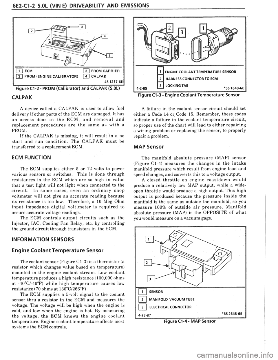
Figure C1-2 - PROM (Calibrator) and CALPAK (5.OL)
CALPAK
ENGINE COOLANT TEMPERATURE SENSOR
HARNESS CONNECTOR TO ECM
LOCKING TAB
4-2-85
*5S 1640-6E
Figure C1-3 - Engine Coolant Temperature Sensor
A device called a CALPAK is used to allow fuel
A failure in the coolant sensor circuit should set
delivery if other parts of the ECM are damaged. It has
either a Code 14 or Code 15. Remember, these codes
an access door in the ECM, and removal and
indicate a failure in the coolant temperature circuit,
replacement procedures are the
same as with a
so proper use of the chart will lead to either repairing
PRO;\/I. a wiring problem or replacing the sensor, to properly
If the CALPAK is missing, it will result in a no
repair a problem.
start
i111d run condition. The CALPAK must be
transferred to a replacement ECM.
MAP Sensor
ECM FUNCTION
The ECM supplies either 5 or 12 volts to power
various sensors or switches. This
is done through
resistances in the ECM which are so high in value
that a test light will not light when connected to the
circuit. In some cases, even an ordinary shop
voltmeter will not give an accurate reading because
its resistance is too low. Therefore, a 10 Meg Ohm
input impedance digital voltlmeter is required to
assure accurate voltage readings.
The ECM controls output circuits such as the
Injector, IAC, Cooling Fan Relay, etc. by controlling
the ground circuit through transistors in the ECM.
INFORMATION SENSORS
Engine Coolant Temperature Sensor
The coolant sensor (Figure C1-3) is a thermistor (a
resistor which changes value based on temperature)
mounted in the engine coolant stream.
[,ow coolant
temperature produces a high resistance
( 100,000 ohms
at
-40°C/-40°F) while high temperature causes low
resistance
(70 ohms at 13O0C/266"F)
The ECM supplies a 5-volt signal to the cooliint
sensor thru a resistor in the ECM and measures the
voltage. The voltage will be high when the engine is
cold,
and low when the engine is hot. By measuring
the voltage, the ECM knows the engine coolant
temperature. Engine coolant temperature affects most
systems the ECM controls. The
manifold absolute pressure
(MAP) sensor
(Figure
(21-4) measures the changes in the intake
manifold pressure which result from engine load and
speed changes, and converts this to a voltage output.
A closed throttle on engine coastdown would
produce a relatively low
MAP output, while a wide-
open throttle would produce a high output. This high
output is produced because the pressure inside the
manifold is the same as outside the manifold, so you
measure 100% of outside air pressure. Manifold
absolute pressure (MAP) is the OPPOSITE of what
you would measure on a vacuum gage.
SENSOR
MANIFOLD VACUUM TUBE
ELECTRICAL CONNECTOR
Figure C1-4 - MAP Sensor
Page 560 of 1825
DRIVEABILITY AND EMISSIONS 5.OL (VIN E) 6EZ-C1-5
DIAGNOSIS
Since the ECM can have a failure which may
effect only one circuit, following the diagnostic
procedures in this section can reliably tell when a
failure has occurred in the ECM. Also,
a Code
55 in
dicates a failure of the ECM.
If a diagnostic chart indicates that the ECM
connections or ECM is the cause of a
problem,and the
ECM is replaced, but does not correct the problem, one
of the following may be the reason:
e
connections. - The diagnostic chart will say "ECM
Connections or ECM". The terminals mav have to be
removed from the connector in order to check them
properly.
@ The ECM or PROM is not correct for the
. - The incorrect ECM or PROM may cause
a malfunction and may or may not set a code.
. - This means that
time the system is
being checked. In this case, refer to the "Symptoms"
portion of the manual and make a careful physical
Solenoids and relays are turned "ON" and "OFF" by
the ECM, using internal electronic switches called
"Drivers".
A shorted solenoid, relay coil, or harness in a
GMP4 computer will not damage the ECM,
but will cause the circuit and controlled
component to be inoperative. When the
circuit fault is not present or has been
repaired, the "Quad-Driver" will again
operate in a normal manner due to it's fault
protected design. If a fault has been repaired
in a circuit controlled
by a "Quad-Driver", the
original
ECM should be reinstalled and the
circuit checked for proper operation.
ECM
replacement will not be necessary if the
repaired circuit or component now operates
correctly.
534636 or BT8405 testers or equivalent provide a
fast, accurate means of checking for a shorted coil or a
short to battery voltage.
e , - Although the
PROM rarely
fails,it operates as part of the ECM.
Therefore, it could be the cause of the problem.
Substitute a known good PROM.
o . - After the
ECM is replaced, the system should be rechecked for
proper operation. If the diagnostic chart again
indicates the ECM is the problem, substitute a known
good ECM. Although this is a rare condition, it could
happen. The
components or circuits and the codes or
charts, related to them are:
@ Code 55 indicates a failure of the ECM.
@ PROM - Code 51.
@ Coolant Temperature Sensor - CHARTS 14 -
15.
@ MAP sensor - CHART 33 or 34. To check the
sensor with no code set, use CHART
C-1D.
e TPS - CHARTS 21 or 22.
e PIN switch - CHART C-1A
@ Crank Signal - CHART C-1B
@ O2 Sensor - CHARTS 13,44,45.
@ VSS - CHART 24 and in TCC System.
e Distributor - CHART 42 and in EST system.
@ Distributor - Chart and in the EST system.
ECM
A faulty ECM will be determined in the diagnostic
charts, or by a Code 55.
PROM
An incorrect or faulty PROM, which is part of the
ECM, may set a Code 51.
ECM INPUTS
All of the sensors and input switches can be
diagnosed by the use of a "Scan" tool. Following is
a
short description of how the sensors and switches can
be diagnosed by the use of "a Scan" tool. The
"Scan"
tool can also by used to compare the values for a
normal running engine with the engine you're
diagnosing.
Coolant Temperature Sensor
A "Scan" tool displays engine temp. in degrees
centigrade. After the engine is started, the
temperature should rise steadily to about
90°C, then
stabilize when thermostat opens.
A fault in the
coolant sensor circuit should set a Code 14 or 15. The
code charts also contain a chart to check for sensor
resistance values relative to temperature.
MAT Sensor
A "Scan" tool displays temperature of the air
entering the engine and should read close ambient air
temperature, when engine is cold, and rise
as
underhood temperature increases. If the engine has
not been run for several hours (overnight), the MAT
sensor temperature and coolant temperature should
read close to each other.
Page 573 of 1825
6E2-C1-18 DRIVEABILITY AND EMISSIONS - 5.OL (VIN E)
CHART C-1 E
POWER SEERING PRESSURE SWIKCH (PSPS) DIAGNOSIS
5.0L (VIN E) "F" SERIES (TBI)
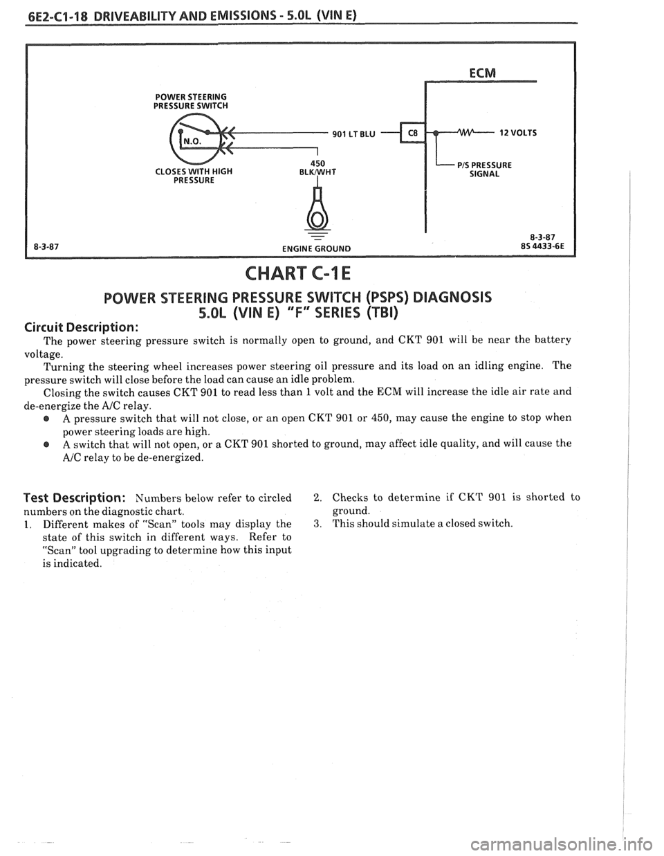
Circuit Description:
The power steering pressure switch is normally open to ground, and CKT 901 will be near the battery
voltage. Turning the steering wheel increases power steering oil pressure and its load on an idling engine. The
pressure switch will close before the load can cause an idle problem.
Closing the switch causes CKT 901 to read less than
1 volt and the ECM will increase the idle air rate and
de-energize the
AJC relay.
A pressure switch that will not close, or an open CKT 901 or 450, may cause the engine to stop when
power steering loads are high.
A switch that will not open, or a CKT 901 shorted to ground, may affect idle quality, and will cause the
AJC relay to be de-energized.
Test Description: Numbers below refer to circled 2. Checks to determine if CKT 901 is shorted to
numbers on the diagnostic chart. ground.
1. Different
makes of "Scan" tools may display the 3. This should simulate a closed switch.
state of this switch in different ways. Refer
to
"Scan" tool upgrading to determine how this input
is indicated.
Page 576 of 1825
DRIVEABILIW AND EMISSIONS - 5.OL (VIN E) 6E2-62-1
SECTION C2
FUEL CONTROL SYSTEM
TBI MODEL 228
CONTENTS
GENERAL DESCRIPTION . . . . . . . . . . . . . . . C2-1
PURPOSE ......................... C2-1
MODES OF OPERATION . . . . . . . . . . . . . . C2-1
Starting Mode . . . . . . . . . . . . . . . . . . . C2-1
Clear Flood Mode . . . . . . . . . . . . . . . . C2-2
RunMode . . . . . . . . . . . . . . . . . . . . . . C2-2
Open Loop . . . . . . . . . . . . . . . . . . . . . . C2-2
Closed Loop . . . . . . . . . . . . . . . . . . . . . C2-2
Acceleration Mode . . . . . . . . . . . . . . . C2-2
Deceleration Mode . . . . . . . . . . . . . . . C2-2
Battery Correction Mode . . . . . . . . . . . C2-2
Fuel Cut Off Mode . . . . . . . . . . . . . . . . C2-2
FUEL CONTROL SYSTEM COMPONENTS
. . . C2-2
BASIC SYSTEM OPERATION . . . . . . . . . . . C2-3
THROTTLE BODY INJECTION (TBI) UNIT. . . C2-3
Fuel Injectors . . . . . . . . . . . . . . . . . . . . C2-3
Pressure Regulator . . . . . . . . . . . . . . . C2-3
ldle Air Control (IAC) Valve . . . . . . . . . . C2-4
Throttle Position Sensor (TPS) . . . . . . . . C2-4
FUEL PUMP.. . . . . . . . . . . . . . . . . . . . . . . C2-5
FUEL PUMP ELECTRICAL CIRCUIT . . . . . . . C2-5
DIAGNOSIS . . . . . . . . . . . . . . . . . . . . . . * C2-5
FUEL CONTROL . . . . . . . . . . . . . . . . . . . . C2-5
GENERAL DESCRIPTION
PURPOSE
The basic function of the fuel control system is to
control fuel delivery to the engine. Fuel is delivered to
the engine by
a throttle body injection ('FBI) unit.
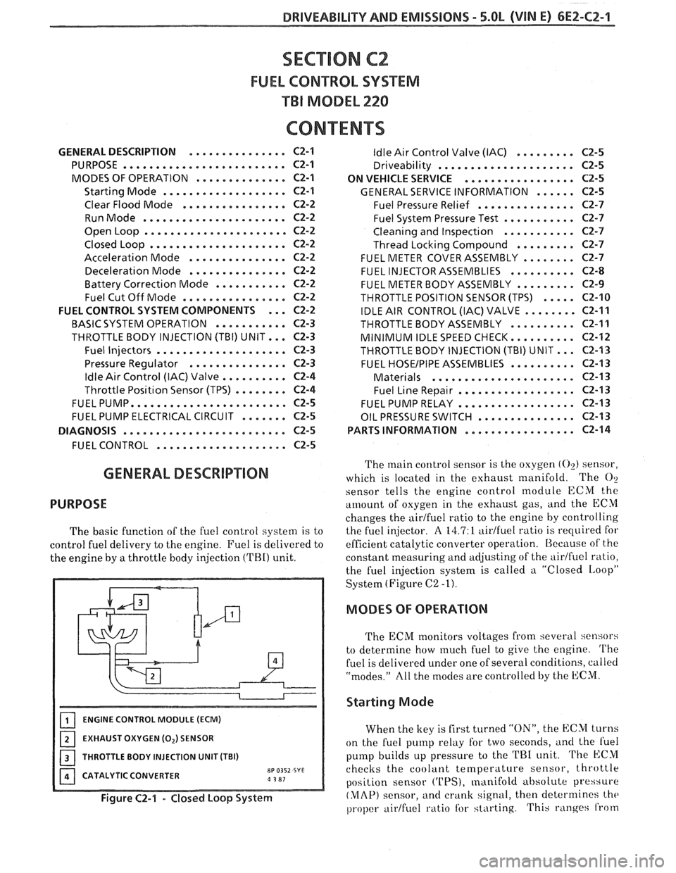
ENGINE CONTROL MODULE (ECM)
EXHAUST OXYGEN (0,) SENSOR
I 1 THROTTLE BODY INJECTION UNIT (TBI)
CATALYTIC CONVERTER
8P 0352 SYE a 3 81
Figure C2-1 - Closed Loop System
ldle Air Control Valve (IAC) . . . . . . . . . C2-5
Driveability . . . . . . . . . . . . . . . . . . . .. C2-5
ON VEHICLE SERVICE
. . . . . . . . . . . . . . . . . C2-5
GENERAL SERVICE INFORMATION . . . . . . C2-5
Fuel Pressure Relief . . . . . . . . . . . . . . . C2-7
Fuel System Pressure Test . . . . . . . . . . . C2-7
Cleaning and Inspection . . . . . . . . . . . C2-7
Thread Locking Compound . . . . . . . . . C2-7
FUEL METER COVER ASSEMBLY . . . . . . . . C2-7
FUEL INJECTOR ASSEMBLIES . . . . . . . . . . C2-8
FUEL METER BODY ASSEMBLY . . . . . . . . . C2-9
THROTTLE POSITION SENSOR (TPS) . . . . . C2-10
IDLE AIR CONTROL (IAC) VALVE . . . . . . . . C2-11
THROTTLEBODYASSEMBLY .......... C2-11
MINIMUM IDLE SPEED CHECK.. . . . . . . . . C2-12
THROTTLE BODY INJECTION (TBI) UNIT.. . C2-I3
FUEL HOSEIPIPE ASSEMBLIES . . . . . . . . . . C2-13
Materials . . . . . . . . . . . . . . . . . . . . . . C2-13
Fuel Line Repair . . . . . . . . . . . . . . . . . . C2-13
FUEL PUMP RELAY . . . . . . . . . . . . . . . . . . C2-13
OIL PRESSURE SWITCH . . . . . . . . . . . . . . . C2-13
PARTS INFORMATION
. . . . . . . . . . . . . . . . . C2-14
The main control sensor is the oxygen (02) sensor,
which is located in the exhaust manifold. The
O?
sensor tells
the engine control module ECM the
amount of osygen in the exhttust gas, and the ECM
changes the airtfuel ratio to the engine by controlling
the fuel injector.
A 14.7: 1 aidfuel ratio is required for
efficient catalytic converter operation. Because of the
constant measuring and adjusting of the
airlfuel ratio,
the fuel injection system is called a "Closed
IAoopP
System (Figure C2 -1).
MODES OF OPERATION
The ECM monitors voltages from several sensors
to determine how
much fuel to give the engine. The
fuel is delivered under one of several conditions, called
"modes." All the modes are controlled by the ECM.
Starting Mode
When the key is first turned "ON", the ECM turns
on the fuel pump relay for two seconds,
i~nd the l'uel
pump builds up pressure to the TRI unit. The ECM
checks the coolant
temperature sensor, throttle
position sensor
('UPS), manifold absolute pressure
(MAP) sensor, and crank signal, then determines the
proper airtfuel ratio tbr starting. This ranges from