1988 PONTIAC FIERO radiator cap
[x] Cancel search: radiator capPage 551 of 1825

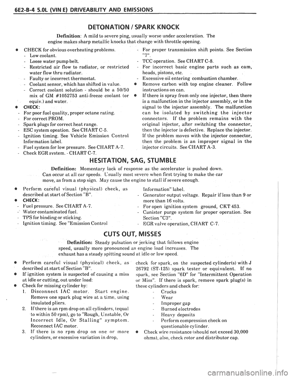
6EZ-B-4 5.OL (VIN E) DRIVEABILITY AND EMISSIONS
DEWNATION 1 SPARK KNOCK
Definition: A mild to severe ping, usually worse under acceleration. The
engine makes sharp metallic knocks that change with throttle opening.
@ CHECK for obvious overheatingproblems. - For proper transmission shift points. See Section
- Low coolant. "7".
- Loose water pump belt. - TCC operation. See CHART C-8.
- Restricted air flow to radiator, or restricted - For incorrect basic engine parts such as cam,
water flow thru radiator. heads,
pistons, etc.
- Faulty or incorrect thermostat. - Excessive oil entering combustion chamber.
- Coolant sensor, which has shifted in value. @ Remove carbon with top engine cleaner. Follow
- Correct coolant solution - should be a 50150 instructions on can.
mix of GM
#lo52753 anti-freeze coolant (or @ If there is spray from only one injector, then there
equiv.) and water. is
a malfunction in the injector assembly, or in the
@ CHECK: signal to the injector assembly. The malfunction
- For poor fuel quality, proper octane rating. can be isolated by switching the injector
- For correct PROM. connectors. If the problem remains with the
- Spark plugs for correct heat range.
original injector, after switching the connector,
- ESC system opeation. See CHART C-5.
then the injector is defective. Replace the injector.
- Ignition timing. See Vehicle Emission Control
If the problem moves with the injector connector,
Information label. then the
problem is an improper signal in the
- Fuel system for low pressure. See CHART A-7.
injector circuits. See CHART A-3.
- Check EGR svstem. - CHART C-7.
HESITATION, SAG, STUMBLE
Definition: Momentary lack of response as the accelerator is pushed down.
Can occur at all car speeds.
C'sually most severe when first trying to make the car
move, as from a stop sign.
May cause the engine to stall if severe enough.
@ Perform careful visual (physical) check, as Information" label.
described at start of Section
"B". - Generator output voltage. Repair if less than 9 or
@ CHECK: more than 16 volts.
- Fuel pressure. See CHART A-7. - For open ignition system ground, CKT 453.
- Water contaminated fuel. - Canister purge system for proper operation. See
- TPS for binding or sticking.
Section "C3".
- Ignition timing. See "Emission Control - EGR valve operation, CHART C-7.
CU"F OUT, MISSES
Definition: Steady pulsation or jerking that follows engine
speed, usually more pronounced as engine load increases. The
exhaust has a steady spitting sound at idle or low speed.
@ Perform careful visual (physical) check, us
described at start of Section
"B".
@ If ignition system is suspected of causing a miss
at idle or cutting, out under load:
@ Check for missing cylinder by:
1. Disconnect IAC motor. Start engine.
Remove one spark plug wire at a time, using
insulated pliers.
2. If there is an rpm drop on all cylinders, (equal
to within 50
rpm), go to "Rough, Unstable, Or
Incorrect Idle, Or Stalling" symptom.
Reconnect
IAC motor.
3. If there is no rpm drop on one or more
cylinders, or excessive variation in drop, check
for spark, on the suspected
cylinder(s) with J
26792 (ST-1251 spark tester or equivalent. If no
spark, see Section
"6D" for "Intermittent Operation
or Miss". If there is spark, remove spark plug(s) in
these cylinders and check for:
- Cracks
- Wear
- Improper gap
- Burned electrodes
- Heavy deposits
- Perform compression check on
questionable cylinder.
@ Check wire resistance (shoulcl not exceed 30,000
ohms), also, check rotor and distributor cap.
Page 1817 of 1825

2 - CHASSIS INDEX
Backup Lamp Switch (Circuit) .......... 8A- 1 12. 7A 1-5
Backup Lights
..................................................... 8B-1
...................................................... Battery Section 6D 1
............................ Battery Specification Chart 6D 1-7
.................................... Body Identification ... .... OA- 1
Borg Warner Rear Axle .......................... Section 4B1
...................................................... Blower Motor 1A-14
Blower Switch
.................................................... 1 A- 13
Booster Assembly
............................................. 5D2-2
Brakes
- General ......................................... Section 5
Adjustment
.................................................... 5C3-4
Booster Assembly
. Tandem
Diaphragm
................... .... ..................... 5D2- 1
................................................ Components 5C3- 1
Diagnosis and Inspection
................................. 5-3
Disc Brake Caliper Assembly
.................................................... 3548 Series 5B6-1
Drum Brake Assembly ........................ Section 5C3
General Description
.......................................... 5-2
On-Car Service
.................................................... 5-7
Specifications & Special Tools ......................... .5 F. 1
...................................................... Unit Repair 5A3- 1
.......................................... Warning System 8A-4 1-0
............ Brake Pedal Mounting .. ......................... 5-1 7
Bulb Usage Chart
............................................ 8B-10
............................................ Bumpers Section 2B,3 D.6
Bumper Energy Absorbing Units
.................... 2B-2
Bench Testing
................................................ 2B-3
........................................ Damage/Leakage 2B-3
................................ Removal After Collision 2B-2
............................................. Fascia Rub Strips .2 B. 1
.................................................... Front Bumper 2B-2
Assembly
........................................................ 2B-4
Energy Absorber
........................................... 2B-4
............................................................. Fascia .2 B. 1
On-Vehicle Service
...................................... 2B-4
Rear Bumper
.................................... .... ............ 2B-2
........................................................ Assembly 2B-5
Energy Absorber
............................................ 2B-4
............. .................... Fascia Molding Strip .. 2B-5 ........................................... Service Procedures .2 B. 1
.................................................. Specifications 2B-5
C
Caliper Assembly . Disc Brake
.............................................. 3000/3 100 Series 5B 1-2
3548 Series
...................................................... 5B6-2
Caliper Overhaul
....................... 3000/3 100 Series .. ............... 5B 1-4
3548 Series
.................................................... 5B6-5
Caster and Camber Adjustment
........................ 3A- 1
............................................. Catalytic Converter 6F-2
Center High-Mounted Stoplight
....................... ... 8B- 1
Charging System
...................... 8A.30.7, Section 6D3
Chassis Electrical
.................................... Section 8B
Center High Mounted Stoplight
...................... 8B-1 ................................. Exterior Light Monitor .8 B. 1
................................................................ Chimes 8A-77
................................ Cigar Lighter (Circuit) 8A- 1
14-0
.............................. Circuit Breaker Details Section 8A
Power ACC Circuit Breaker .... 8A- 10.1.10.3.10.5.
11-3
.... Window Circuit Breaker 8A~10~1,10~3.10~5.1 1.4
Clutch
........................................................ Section 7C
......................................... General Description .7 C. 1 ........................................................... Diagnosis 7C-2 Bleeding
Hydraulic Clutch System
................. .7 C.2
Preliminary Checks ..................................... ... 7C-2
On-Vehicle Service
........................................... 7C-5
Clutch Hydraulic System
.................................. 7C-5
Clutch Pedal ...................................................... 7C-6
Pilot Bearing
..................................................... 7C-6
Pressure Plate and Disc
.................................... 7C-6
Special Tools
......................... ....... ................ 7C-8
Specifications
................................................... 7C-8
Coil Springs and Insulators .............................. 3D-1
Component Fluid Capacities
................................ OB-6
Component Location Views
........................ 8A-201-0
Composite Master Cylinder
................... Section 5A3
Compression Test
.................. .. ............................. 6-5
Condenser Mounting
....................................... 1B 1-24
Connectors
.................................................... 8A-202-0
Coolant Fan Temperature Switch
...................... 8A-3 1
Cooling and Radiator
................................ Section 6B
Cooling System Capacities
................................. OB-6
Cooling System Diagnosis
.................................... 6B-3
Cranking System
...................................... Section 6P*
Diagnosis ..................................................... 6~2
General Description ................................ 6D2- 1
Cranking System
........................................ 6D2- 1
Solenoid
................................................... 6D2- 1
Starter Motor ......................................... 6D2-1
On-Vehcile Service
...................................... 6D2-4
Specifications
............................................ 6D2- 1
Starter
........................................................ 6D2-4
Unit Repair
............................................ 6D2-6- 11
Service Procedures
...................................... 6D2-3
Cruise Control
.............................. 8A-34-0, Section 9B
Diagnosis
............................................................ 9B-4
Cruise Set Speed High or Low
.................... 9B-4
Cruise System Surges
.................................. 9B-4
Cruise Tap-Up and Tap-Down
...................... 9B-4
Excessive Cruise Speed Loss on
Hills
........................................................... 9B-4
General Description
........................................ 9B-1
Electrical and Vacuum Release
Switches
...................................................... 9B-4
Electrical Harness
.......................................... 9B-A
Electronic Controller (Module) .................... 9B .
Off/On/Resume/Accel Switch
Operation
.................................................. .91 B-
Servo Unit
.................................................... 9B-2
Set/Coast Button Switch .............................. 9B-1
................................................ Speed Sensors 9B-3
Vacuum Supply
............................................ 9B-4
On-Car Service
.................................................. 9B-6
................................ Cruise Release Switches 9B-6
.......................................... Servo Mounting 9B-10
Vacuum Harness and Cable Routing
VIN
E ................................. .. .................. 9B,7
.................................................... VIN F, 8 9B-9
....................................................... VIN S 9B-8
........................ Vacuum Tank - VIN S,F,E, 9B-10
.............................. Cruise Control (Circuit) 8A-34-0
D
......................................... Defogger (Circuit) $A-6 1-0
..................... ...... Defroster Duct Assembly ... .812 C-
Diagnosis
Air Conditioning
- General ........................... 1B-5
.................... Automatic Transmission - General 7A
Automatic Transmission
- ................ HD-700-R4-2
Page 1819 of 1825

4 . CHASSIS INDEX
Fitting Pistons ......................................... .6A 2.24
Front (Cover) Crankshaft Oil
Seal
V-6
......................................................... 6A2- 15
V-8
................................................... 6A3- 16
Gear or Sprocket
V-6
......................................................... .6A 2.26
V-8
........................................................ 6A2-28
Honing and Reboring Cylinders ................ 6A2-23
Intake Manifold and Gasket
V-6
......................................................... .6A 2.9
V-8
............................................................ 6A3-6
Main Bearings
V-6
......................................................... .6A 2. 19
V-8
.......................................................... 6A3-20
Oil Filter and Bypass Valve
...................... 6A3-27
Oil Pan and Pump Assembly
V-6
................................................. 6A2.17, 18
V-8
......................................................... 6A3- 18
Oil Seal (Front Cover)
V-6
......................................................... 6A2- 15
V-8 .......................................................... 6A3-16
Piston and Connecting Rod
V-6
......................................................... .6A 2.2 1
V-8
....................................................... .6A 3.23
Piston Rings V-6
......................................................... .6A 2.24
V-8
........................................................ .6A 3.23
Power Train Mounts
V-6
........................................................... .6A 2.7
V-8
.......................................................... 6A3-5
Rear Main Oil Seal
V-6
......................................................... .6A 2.2 1
V-8 ......................................................... .6A 3.22
Rocker Arm Assembly
V-6
............................................................ 6A2-8
V-8 ............................................................ 6A3-8
Rocker Arm and Push Rod
V-6
........................................................... .6A 2.8
V-8
........................................................ 6A3-8
Rocker Arm Studs 6A2- 13
V-6
......................................................... .6A 2. 13
V-8
.......................................................... 6A3-28
Sprocket or Gear Replacement
V-6
......................................................... .6A 2.26
V-8 .......................................................... 6A3-28
Timing Chain and Sprockets
6A2- 15
Torsional Damper
V-6
.......................................................... 6A2- 14
V-8
.......................................................... 6A3- 15
Valves V-6
........................................ .. ............... .6A 2. 14
V-8
......................................................... .6A 2. 15
Valve Guides
V-6
......................................................... .6A 2. 13
V-8
.......................................................... 6A3-14
Valve Lifters
V-6
......................................................... .6A 2. 1 1
V-8
.......................................................... 6A3-10
Valve Mechanism .................................... 6A 10
Valve Seats
V-6
....................................................... .6A 2. 14
V-8
.......................................................... 6A3-14
Valve Spring
.......................................................... V-6 A- 16
............................................................ V-8 6A3-9
................................. Valve Stem Oil Seal .6A 2. 10 Engine Cooling
........................................... Section
6B
Aluminum Radiator Service
............................ 6B-8
Diagnosis
........................................................ 6B-3. 8
Coolant System .............................................. 6B-4
Leak Testing
.................................................. 6B-8
On-Vehicle Pressure Testing
.......................... 6B-9
Repair Methods
........................................... 6B- 10
Special Tools
.............................................. 6B-14
General Description ......................................... .6 B- 1
Coolant Recovery System
.............................. 6B-3
Coolant Temperature Fan Switch
................ 6B-2
Fans
.............................................................. 6B-2
Radiator
...................................................... 6B-1
Radiator Cap
.................................................. 6B-1
Recovery Bottle
.............................................. 6B-2
Temperature Switch
...................................... 6B-2
Thermostat
.................................................... 6B-3
On-Vehicle Service
......................................... 6B- 14
Coolznt Recovery Bottle
............................. .6 B- 16
Electric Cooling Fan
................................... .6 B- 15
Radiator
....................................................... 6B1'
Thermostat ................................................ 5B-, .
Water Pump ................................... .... ......... 6B-15
Service Procedures
............................................ 6B-3
Cooling System Cure
................................. ... 6B-3
Draining and Refilling the
Cooling System
......................................... 6B-7
Drive Belt
................................................... 6B-7
Engine Electrical ...................................... Section 6D
Battery
............................................................. 6D1
Diagnosis
................................................... 6D 1-2
General Description
.................................. 6D 1-1
On-Car Service
.......................................... 6D 1-5
Charging System
............................................... 6D3
Diagnosis
.................................................... 6D3- 1
General Description
.............................. 6D3- 1
On-Vehicle Service
.................................... 6D3-2
Service Procedures
................................. 6D3- 1
Cranking System .......................... ........ ............ 6D2-
Diagnosis .................................................... 6D2- 1 I
General Description .................................. 6D2- 1
On-Car Service
......................................... 6D2J
................ . Engine Wiring .............................. ... 6D
General Description .................................. 6D5- 1
Ignition System
................................................. 6D4
Diagnosis
................................................... 6D4- 1
General Description
............................... 6D4- 1
On-Car Service
.......................................... 6D4-5
Service Procedures
.................................... 6D4-3
Engine Exhaust Systems
...................................... 6F
Engine
- General Information .............................. 6-1
Compression Test
................................................ 6-5
Engine Knock Diagnosis
................................. 6-4
Engine Mechanical
.............................................. 6-3
Engine Performance Diagnosis
.......................... 6-3
Engine Oil Pressure Light
.................................... 8C-3
Engine Performance Specifications
Chart
........................................................ 6E3-C13-3
Evaporator Core
.............................................. 1B 1-24
Exhaust Systems
.......................................... Section 6F
Catalytic Converters
........................................ 6F- 1
Clamp
................................................................ 6F- 1
Component Replacement
.................................. 6F-2
Hangers
......................................................... 6F- 1
Muffler ............................................................. 6F- 1
Removing and Installing Parts ........................ 6F-2
Resonator .......................................................... 6F- 1