1988 PONTIAC FIERO oil filter
[x] Cancel search: oil filterPage 869 of 1825
6E3-B-4 5.OL (VIN F) & 5.7L (VIN 8) DRIVEABILITY AND EMISSIONS
LACK OF POWER, SLUGGISH, OR SPONGY
Definition: Engine delivers less than expected power. Little or
no increase in speed when accelerator pedal is pushed down part way.
@ Perform careful visual check as described at
start of Section "B".
@ Compare customer's car to similar unit.
Make sure the customer's car has an actual
problem.
@ Remove air cleaner and check air filter for
dirt, or for being plugged. Replace as
necessary.
@ CHECK:
- For loose or leaking air duct between MAF
sensor and throttle body.
- Ignition timing. See emission control
information label.
- Restricted fuel filter, contaminated fuel or
improper fuel pressure. See CHART A-7.
- ECM Ground circuits - See ECM wiring
diagrams.
- EGR operation for being open, or partly open
all the time
- CHART C-7.
- Exhaust system for possible restriction: See
CHART
B-1.
- Inspect exhaust system for damaged or
collapsed pipes.
- Inspect muffler for heat distress or possible
internal failure.
- For possible plugged catalytic convertor by
comparing exhaust system backpressure on
each side at engine. Check backpressure by
removing
A.1.R check valves near exhaust
manifolds. See CHART
B-1 for procedure.
- Generator output voltage. Repair if less than 9
or more than 16 volts.
- Engine valve timing and compression.
- Engine for proper or worn camshaft. See Section
"6A".
- Secondary voltage using a shop ocilliscope or a
spark tester
5-26792 (ST-125) or equivalent.
- Check for excessive knock retard. See CHART
C-5.
DETONATION ISPARK KNOCK
Definition: A mild to severe ping, usually worse under
acceleration. The engine makes sharp metallic knocks that
change with throttle opening. Sounds like popcorn popping.
@ Check for obvious overheating problems:
- Low coolant.
- Loose water pump belt.
- Restricted air flow to radiator, or restricted
water flow thru radiator.
- Inoperative electric cooling fan circuit. See
CHART C-12.
@ CHECK:
- Ignition timing. See vehicle emission control
information label.
- EGR system for not opening - CHART C-7.
- TCC operation - CHART C-8.
- Fuel system pressure. See CHART A-7.
- Mem-Cal - Be sure it's the correct one. (See
"Service Bulletins").
- Valve oil seals for leaking.
@ Check for incorrect basic engine parts such as
cam, heads, pistons, etc.
@ Checkforpoorfuelquality.
@ Remove carbon with top engine cleaner. Follow
instructions on can.
@ Check ESC system
See CHART C-5
@ To help determine if the condition is caused by a
rich or lean system, the car should be driven at
the speed of the complaint. Monitoring block
learn at the complaint speed will help identify the
cause of the
problem. If the system is runnig lean
(block learn greater than
1381, refer to
"Diagnostic Aids" on facing page of Code
44. If
the system is running rich (block learn less than
1181, refer to "Diagnostic Aids" on facing page of
Code 45.
Page 870 of 1825
DRIVEABILITY AND EMISSIONS S.OL (VIN F) & 5.7L (VIN 8) 6E3-B-5
Definition: Steady pulsation or jerking that follows engine
speed, usually more pronounced as engine load increases. The
exhaust has
a steady spitting sound at idle or low speed.
@ Perform careful visual check as described at blink
at any connector, it is a faulty injector drive
start of Section
"B". circuit harness, connector, or terminal.
@ Check for missing cylinder by: @ Perform the Injector Balance Test. See CHART
1. Disconnect IAC valve. Start engine. C-2A.
Remove one spark plug wire at a time
@ CHECK:
using insulated pliers. - Spark plug wires by connecting ohmmeter to
2. If there is an rpm drop on all cylinders ends
of each wire in question. If meter reads over
(equal to within
50 rpm), go to "ROUGH, 30,000
ohms, replace wire(s).
UNSTABLE, OR INCORRECT IDLE, - Fuel System - Plugged fuel filter, water, low
STALLING" symptom. Reconnect IAC pressure. See CHART A-7.
valve.
- Valve timing.
3. If there is no rpm drop on one or more - Secondary voltage using a shop ocilliscope or a
cylinders, or excessive variation in drop, spark tester 5-26792 (ST-125)
or equivalent.
check for spark on the suspected
@ Visually inspect distributor cap and rotor for
cylinder(s) with J 26792 (ST-125) Spark moisture, dust, cracks, burns, etc. Spray cap and
Gap Tool or equivalent. If no spark, see plug wires with fine water mist to check for
Section 6D for Intermittent Operation or shorts.
Miss. If there is spark, remove spark
@ A miss condition can be caused by EM1
plug(s) in these cylinders and check for: (Electromagnetic Interference) on the reference
- Cracks circuit. EM1 can usually be detected by
- Wear monitoring engine rpm with a "Scan" tool. A
- Improper Gap sudden
increase in rpm with little change in
- Burned Electrodes actual engine rpm change, indicates EM1 is
- Heavy Deposits present.
@ Perform compression check on questionable If
the problem exists, check routing of secondary
cylinder(s) found above. If compression is low, wires, check
all distributor ground circuits.
repair as necessary. See Section
"6". @ Remove rocker covers. Check for bent pushrods,
@ Disconnect all injector harness connectors. worn
rocker arms, broken valve springs, worn
Connect
5-34730-2 Injector Test Light or camshaft
lobes. Repair as necessary. See Section
equivalent 6 volt test light between the
"6A".
harness terms, of each injector connector and
note light while cranking. If test light fails to
BACKFIRE
Definition: Fuel ignites in intake manifold, or
in exhaust system, making a loud popping noise.
@ CHECK: - Spark plugs for crossfire also inspect (distributor
- Loose wiring connector or air duct at MAF
cap, spark plug wires, and proper routing of plug
sensor. wires).
- Compression - Look for sticking or leaking - Ignition system for intermittent condition. (See
valves. Section
"6D").
- EGR operation for being open all the time. See - Engine timing - see emission control information
CHART C-7. label.
- EGR gasket for faulty or loose fit. - Perform fuel system diagnosis check, CHART A-
- Valve timing. 7A.
- Output voltage of ignition coil using a shop - Perform injector balance test CI-IART C-2A.
ocilliscope or spark tester 5-26792 (ST-125) or
- A.I.R. system check valves - See Section "C-6".
equivalent.
Page 890 of 1825
DRIVEABILITY AND EMISSIONS 5.OL (VIN F) & 5.7L (VIN 8) 6E3-CZ-3
Deceleration Mode
The ECM looks at changes in throttle position and
air flow to reduce the amount of fuel. When
deceleration is very fast, the ECM may shut off fuel
completely for short periods.
Battery Voltage Correction Mode
When battery voltage is low, the ECM can
compensate for the weak spark delivered by the
distributor by:
@ Increasing the amount of fuel delivered;
@ Increasing the idle rpm; and
@ Increasing ignition dwell time.
Fuel Cutoff Mode
No fuel is delivered by the injector when the
ignition is "OFF". This prevents dieseling. Also, fuel
is not delivered if no reference pulses are seen from
the distributor, which means the engine is not
running. This prevents flooding.
FUEL CONTROL SYSTEM
Basic System Operation
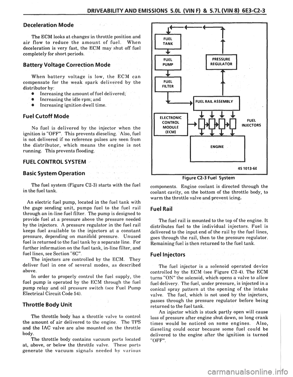
The fuel system (Figure C2-3) starts with the fuel
in the fuel tank.
An electric fuel pump, located in the fuel tank with
the gage sending unit, pumps
fuel to the fuel rail
through an in-line fuel filter. The pump is designed to
provide fuel at a pressure above the pressure needed
by the injectors. A pressure regulator in the fuel rail
keeps fuel available to the injectors at
a constant
pressure, depending on manifold pressure. Unused
fuel is returned to the fuel tank by a separate line. For
further information on the fuel tank, in-line filter, and
fuel lines, see Section
"6C".
The injectors are controlled by the ECM. They
deliver fuel in one of several modes, as described
above. In order to properly control the fuel supply, the
fuel pump is operated by the
ECM through the fuel
pump relay and oil pressure switch (see Fuel Pump
Electrical Circuit Code
54).
Throttle Body Unit
The throttle body has a throttle valve to control
the amount of air delivered to the engine. The TPS
and the IAC valve are also mounted on the throttle
body. The throttle body contains vacuum ports located
at, above, or below the
throttIe valve. 'I'hese ports
generate the vacuum signals
needed I,y v~irious
Figure C2-3 Fuel System
components. Engine coolant is directed through the
coolant cavity, on the bottom of the throttle body, to
warm the throttle valve and prevent icing.
Fuel Rail
The fuel rail is mounted to the top of the engine. It
distributes fuel to the individual injectors. Fuel is
delivered to the input end of the rail by the fuel lines,
goes through the rail, then to the pressure regulator.
Remaining fuel is then returned to the fuel tank.
Fuel Injectors
The fuel injector is a solenoid operated device
controlled by the ECM (see Figure
C2-4). The ECM
turns
"ON" the solenoid, which opens a valve to allow
fuel delivery.
The fuel, under pressure, is injected in a
conical spray pattern at the opening of the intake
valve. The fuel, which is not used by the injectors,
passes through the pressure regulator before being
returned to the fuel tank.
An injector which is stuck partly open will cause
loss of pressure after engine shut down, so long crank
times would be noticed on some engines. Also,
dieseling could occur because some fuel could be
delivered to the engine after the ignition is turned
"OFF".
Page 929 of 1825
6E3-C6-2 5.OL (VIN F) & 5.7L (VIN 8) DRIVEABILITY AND EMISSIONS
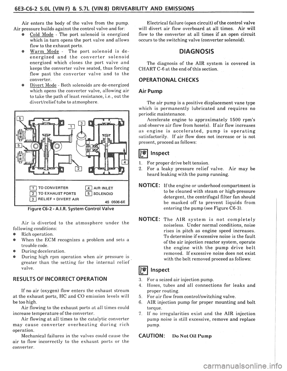
Air enters the body of the valve from the pump.
Air pressure builds against the control valve and for:
@ Cold Mode - The port solenoid is energized
which in turn opens the port valve and allows
flow to the exhaust ports.
Warm Mode
- The port solenoid is de-
energized and the converter solenoid
energized which closes the port valve and
keeps the converter valve seated, thus forcing
flow past the converter valve and to the
converter.
@ Divert Mode - Both solenoids are de-energized
which opens the converter valve, allowing air
to take the path of least resistance,
i.e., out the
divertlrelief tube to atmosphere. Electrical
failure (open circuit) of the control valve
will divert air flow overboard at all times. Air will
flow to the converter at all times if an open circuit
occurs to the switching valve (converter solenoid).
DIAGNOSIS
The diagnosis of the AIR system is covered in
CHART C-6 at the end of this section.
OPERATIONAL CHECKS
Air Pump
The air pump is a positive displacement vane type
which is permanently lubricated and requires no
periodic maintenance.
llccelerate engine to approximately 1500 rpm's
and observe air flow from hose(s). If air flow increases
as engine is accelerated, pump is operating
satisfactorily. If air flow does not increase or is not
present, proceed as follows:
Inspect
I. For proper drive belt tension.
2. For a leaky pressure relief valve. Air may be
heard leaking with the pump running.
TO CONVERTER AIR INLET
TO EXHAUST PORTS
1 SOLENOID
Figure C6-2 - A.I.R. System Control Valve
Air is diverted to the atmosphere under the
lowing conditions:
Rich operation.
When the
ECM recognizes a problem and sets a
trouble code.
@ During deceleration.
During high rprn operation when air pressure is
greater than the setting
for the internal relief
valve.
RESULTS OF INCORRECT OPERATION
If no air (oxygen) flow enters the exhaust stream
at the exhaust ports, I-IC and CO emission levels will
be too high.
Air flowing to the exhaust ports at all times could
increase temperature of the converter.
Air flowing at all times to the catalytic converter
may cause converter overheating during rich
a ion.
oper
t'
Mechanical failures in the valves could cause the
air to flow incorrectly to the exhaust ports or the
converter.
NOTICE : If the engine or underhood compartment is
to be cleaned with steam or high-pressure
detergent, the centrifugal filter fan should
be masked off to prevent liquids from
entering the pump (see Figure
C6-3).
NOTICE: The AIR system is not completely
noiseless. Under normal conditions, noise
rises in pitch as engine speed increases.
To determine if excessive noise is the fault
of the air injection reactor system, operate
the engine with the pump drive belt
removed. If excessive noise does not exist
with the belt removed proceed as follows:
a inspect
3. For a seized air injection pump.
4. Hoses, tubes and all connections for leaks and
proper routing.
5. For air flow from control/switching valve.
6. AIR injection pump for proper mounting and bolt
torque.
7. If no irregularities exist and the AIR injection
pump noise is still excessive, remove and replace
Pump.
CAUTION: 110 Not Oil Pump
Page 999 of 1825
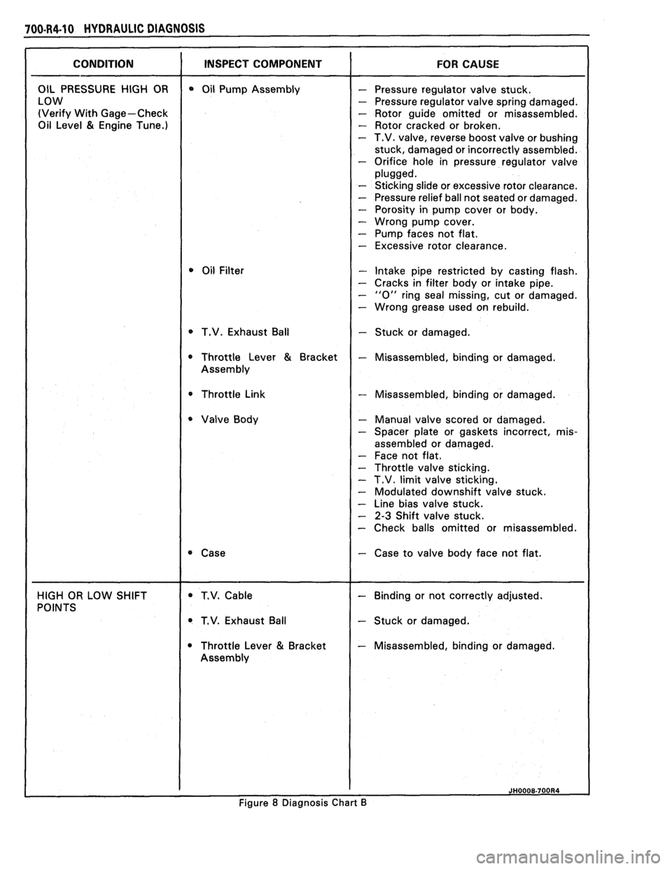
100.R4.10 HYDRAULIC DIAGNOSIS
(Verify With Gage-Check - Rotor guide omitted or misassembled.
Oil Level
81 Engine Tune.) - Rotor cracked or broken. - T.V. valve, reverse boost valve or bushing
stuck, damaged or incorrectly assembled.
- Orifice hole in pressure regulator valve
- Sticking slide or excessive rotor clearance.
- Pressure relief ball not seated or damaged.
- Porosity in pump cover or body.
- Wrong pump cover.
- Pump faces not flat.
- Excessive rotor clearance.
- Intake pipe restricted by casting flash.
- Cracks in filter body or intake pipe.
- "0" ring seal missing, cut or damaged.
- Wrong grease used on rebuild.
T.V. Exhaust Ball
- Stuck or damaged.
* Throttle Link - Misassembled, binding or damaged.
- Manual valve scored or damaged.
- Spacer plate or gaskets incorrect, mis-
assembled or damaged.
- Face not flat.
- Throttle valve sticking.
- T.V. limit valve sticking.
- Modulated downshift valve stuck.
- Line bias valve stuck.
- 2-3 Shift valve stuck.
- Check balls omitted or misassembled.
- Case to valve body face not flat.
T.V. Exhaust Ball
- Stuck or damaged.
Throttle Lever
81 Bracket - Misassembled, binding or damaged.
Figure
8 Diagnosis Chart B
Page 1007 of 1825
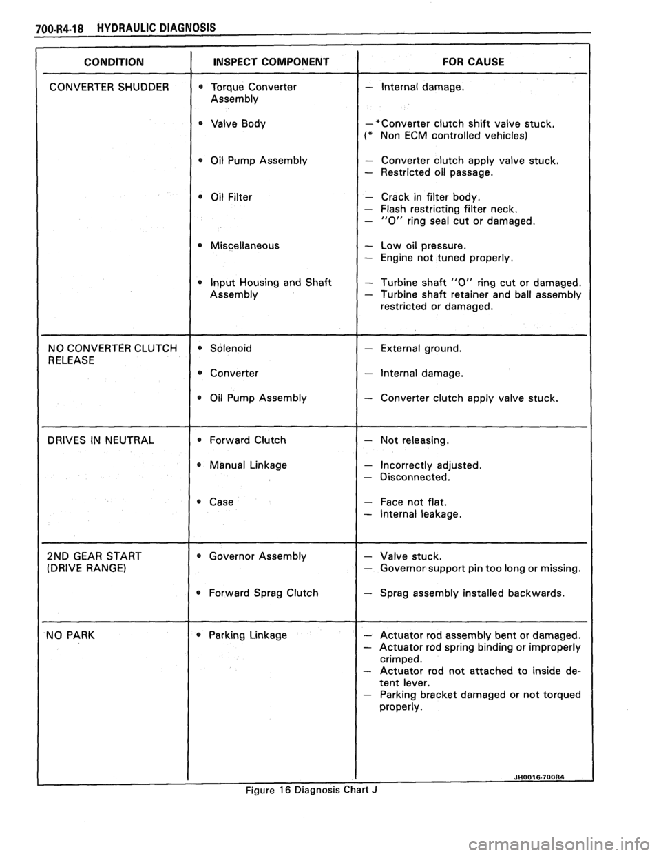
-*Converter clutch shift valve stuck.
(* Non ECM controlled vehicles)
0 Oil Pump Assembly - Converter clutch apply valve stuck.
- Restricted oil passage.
- Crack in filter body.
- Flash restricting filter neck. - "0" ring seal cut or damaged.
0 Miscellaneous - Low oil pressure.
- Engine not tuned properly.
0 Input Housing and Shaft - Turbine shaft "0" ring cut or damaged. - Turbine shaft retainer and ball assembly
restricted or damaged.
- lnternal damage.
Oil Pump Assembly
- Converter clutch apply valve stuck.
0 Manual Linkage - Incorrectly adjusted.
- Disconnected.
- Face not flat.
- lnternal leakage.
pport pin too long or missing.
0 Forward Sprag Clutch Sprag assembly installed backwards.
- Parking bracket damaged or not torqued
Figure
16 Diagnosis Chart J
Page 1054 of 1825
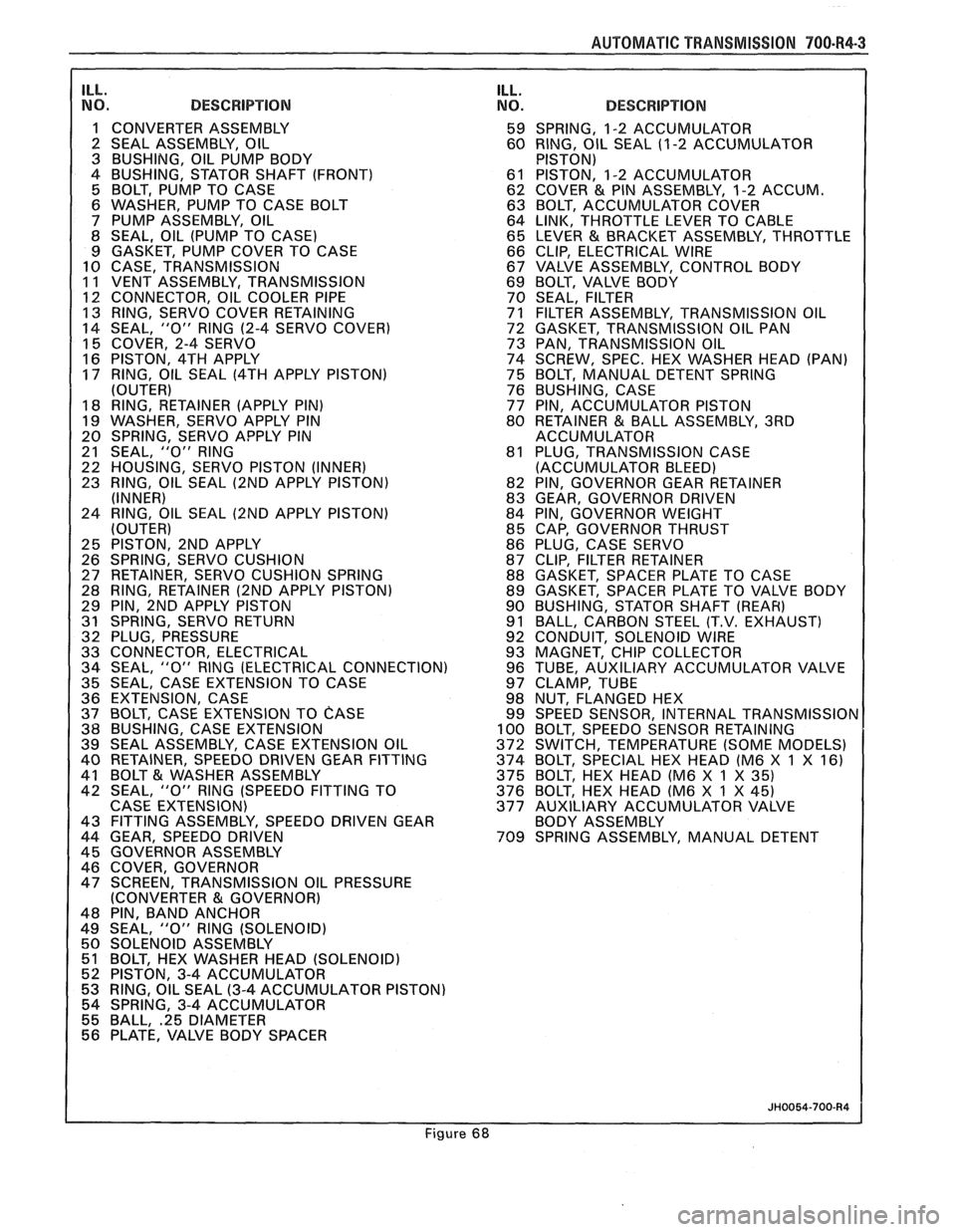
AUTOMAT lC TRANSMISSION 700-R4-3
ILL. NO. DESCRIPTION
1 CONVERTER ASSEMBLY
2 SEAL ASSEMBLY, OIL
3 BUSHING, OIL PUMP BODY
4 BUSHING, STATOR SHAFT (FRONT)
5 BOLT, PUMP TO CASE
6 WASHER, PUMP TO CASE BOLT
7 PUMP ASSEMBLY, OIL
8 SEAL, OIL (PUMP TO CASE)
9 GASKET, PUMP COVER TO CASE
10 CASE, TRANSMISSION
11 VENT ASSEMBLY, TRANSMISSION
1 12 CONNECTOR, OIL COOLER PIPE 13 RING, SERVO COVER RETAINING
14 SEAL, "0" RlNG
(2-4 SERVO COVER)
15 COVER, 2-4 SERVO
16 PISTON, 4TH APPLY
17 RING, OIL SEAL
(4TH APPLY PISTON)
(OUTER)
18 RING, RETAINER (APPLY PIN)
19 WASHER, SERVO APPLY PIN
20 SPRING, SERVO APPLY PIN
21 SEAL,
"0" RlNG
22 HOUSING, SERVO PISTON (INNER)
23 RING, OIL SEAL
(2ND APPLY PISTON)
(INNER)
24 RING, OIL SEAL
(2ND APPLY PISTON)
(OUTER)
25 PISTON, 2ND APPLY
26 SPRING, SERVO CUSHION
27 RETAINER, SERVO CUSHION SPRING
28 RING, RETAINER
(2ND APPLY PISTON)
29 PIN, 2ND APPLY PISTON
31 SPRING, SERVO RETURN
32 PLUG, PRESSURE
33 CONNECTOR, ELECTRICAL
34 SEAL,
"0" RlNG (ELECTRICAL CONNECTION)
35 SEAL, CASE EXTENSION TO CASE
36 EXTENSION, CASE
37 BOLT, CASE EXTENSION TO
CASE 38 BUSHING, CASE EXTENSION
39 SEAL ASSEMBLY, CASE EXTENSION OIL
40 RETAINER, SPEEDO DRIVEN GEAR FITTING
41 BOLT
& WASHER ASSEMBLY
42 SEAL, "0" RlNG (SPEEDO FITTING TO
CASE EXTENSION)
43 FITTING ASSEMBLY, SPEEDO DRIVEN GEAR
44 GEAR, SPEEDO DRIVEN
45 GOVERNOR ASSEMBLY
46 COVER, GOVERNOR
47 SCREEN, TRANSMISSION OIL PRESSURE
(CONVERTER
81 GOVERNOR)
48 PIN, BAND ANCHOR
49 SEAL,
"0" RlNG (SOLENOID)
50 SOLENOID ASSEMBLY
51 BOLT, HEX WASHER HEAD (SOLENOID)
52 PISTON, 3-4 ACCUMULATOR
53 RING, OIL SEAL
(3-4 ACCUMULATOR PISTON)
54 SPRING, 3-4 ACCUMULATOR
55 BALL,
.25 DIAMETER 56 PLATE, VALVE BODY SPACER
ILL. NO. DESCRIPTION
59 SPRING, 1-2 ACCUMULATOR
60 RING, OIL SEAL (1
-2 ACCUMULATOR
PISTON)
61 PISTON, 1-2 ACCUMULATOR
62 COVER
& PIN ASSEMBLY, 1-2 ACCUM.
63 BOLT, ACCUMULATOR COVER
64 LINK, THROTTLE LEVER TO CABLE
65 LEVER
& BRACKET ASSEMBLY, THROTTLE
66 CLIP, ELECTRICAL WIRE
67 VALVE ASSEMBLY, CONTROL BODY
69 BOLT, VALVE BODY
70 SEAL, FILTER
71 FILTER ASSEMBLY, TRANSMISSION OIL
72 GASKET, TRANSMISSION OIL PAN
73 PAN, TRANSMISSION OIL
74 SCREW, SPEC. HEX WASHER HEAD (PAN)
75 BOLT, MANUAL DETENT SPRING
76 BUSHING, CASE
77 PIN, ACCUMULATOR PISTON
80 RETAINER
& BALL ASSEMBLY, 3RD
ACCUMULATOR
81 PLUG, TRANSMISSION CASE
(ACCUMULATOR BLEED)
82 PIN, GOVERNOR GEAR RETAINER
83 GEAR, GOVERNOR DRIVEN
84 PIN, GOVERNOR WEIGHT
85 CAP, GOVERNOR THRUST
86 PLUG, CASE SERVO
87 CLIP, FILTER RETAINER
88 GASKET, SPACER PLATE TO CASE
89 GASKET, SPACER PLATE TO VALVE BODY
90 BUSHING, STATOR SHAFT
(REAR)
91 BALL, CARBON STEEL (T.V. EXHAUST)
92 CONDUIT, SOLENOID WIRE
93 MAGNET, CHIP COLLECTOR
96 TUBE, AUXILIARY ACCUMULATOR VALVE
97 CLAMP, TUBE
98 NUT, FLANGED HEX
99 SPEED SENSOR, INTERNAL
TRANSMISSIOr 100 BOLT, SPEEDO SENSOR RETAINING
372 SWITCH, TEMPERATURE (SOME MODELS)
374 BOLT, SPECIAL HEX HEAD (M6 X
1 X 16)
375 BOLT, HEX HEAD (M6 X 1 X
35) 376 BOLT, HEX HEAD (M6 X 1 X 45)
377 AUXILIARY ACCUMULATOR VALVE
BODY ASSEMBLY
709 SPRING ASSEMBLY, MANUAL DETENT
Figure 68
Page 1056 of 1825
AUTOMA"PI&: TRANSMISSION 780-R4-5
5. Case extension bolts (37)
and case extension (36)
6. Extension seal ring (35)
7. Output
shaft sleeve (690) and output shaft o-ring
seal (691)
- Not all models use an output shaft sleeve
and seal
a Remove or Disconnect (Figures 75)
Models with Mechanical Speedometer
1. Speedometer drive gear
(689) and clip (688)
- push tab of retaining clip and tap
speedometer gear off the output shaft.
- use care not to damage the speedo gear
Valve Body and Wiring Harness
Remove or Disconnect (Figures 76, 77)
1. Screws (74), oil
pan (73), and gasket (72).
2. Oil filter
(71) and filter seal (70).
- Filter seal may be stuck in the case
3. Outside
electrical connector (33) and o-ring seal
(34).
4. Electrical connections from switches.
- refer to wiring diagrams in the Hydraulic
Diagnosis Section for specific model
applications
5. Solenoid bolts
(51) and solenoid assembly (50)
with o-ring seal (49) and wiring harness.
6. Accumulator cover bolts (63) and 1-2
accumulator cover and pin assembly (62).
7. 1-2 accumulator piston (61) and seal (60).
8. Spring (59).
Remove or Disconnect (Figures 78,99,88 and 81)
1. Bolt (75) and manual detent spring assembly
(709).
2. Electrical wire clips (66) and tube clamps (97).
3. Auxiliary valve tube (96).
4. Wiring harness retaining washer (A) and the
filter retainer clips
(87).
5. Bolts (69) and T.V. lever and bracket assembly
(65)
6. T.V. link (64)
Remove or Disconnect (Figures 78,88,8'1 and 82)
1. Remaining valve body bolts (69)
2. Manual valve link (705)
3. Control valve assembly (67)
4. Bolts
(374-376), auxiliary valve body (377), and
check
ball (55)
5. Spacer plate (56) and spacer plate gaskets (88 and
89)
6. Check balls (55 and 91) spring (54), piston (52),
sea1 (53) and pin
- Three checkballs are located under the
valve body, one in the auxiliary valve body
and four are located in the case. The large
copper flash colored ball is
# 10 check ball
(9 1)
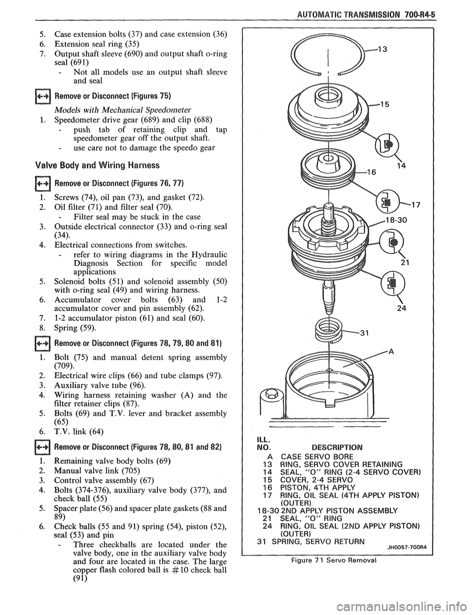
ILL.
NO.
A
13 14
15 16
17
DESCBPlPT!ON
CASE SERVO BORE
RING,
SERVO COVER RETAINING
SEAL, "0" RING (2-4 SERVO COVER)
COVER, 2-4 SERVO
PISTON, 4TH APPLY
RING,
OIL SEAL (4TH APPLY PISTON) (OUTER)
18-30 2ND AP'PLY PISTON ASSEMBLY 21 SEAL, "0" RlNG
24 RING, OIL SEAL (2ND APPLY
PISTON)
(OUTER) 31 SPRING, SERVO RETURN JH0057-700R4
Figure 7 1 Servo Removal