1988 PONTIAC FIERO air condition
[x] Cancel search: air conditionPage 1694 of 1825
GENERAL INFORMATION 5 F STYLE 1H-13
4. Prime entire area with 3M Polyolefin Adhesion
Promoter Part
kt05907 or equivalent before
filling with 3M Flexible Parts Repair Material
kt05900 or equivalent.
5. Shape repair material with curved body tooth file.
Then block sand with
#220 grit disc and final
featheredge with
#320 grit disc.
6. If low areas or pits remain, first reapply 3M
Polyolefin Adhesion Promoter or equivalent,
then mix and spread additional repair material.
Painting Flexible Parts - E/P or TPO
When painting flexible plastic exterior parts
identified as E/P or TPO, a polypropylene primer
must be used. Follow manufacturer's label
instructions.
METAL REPLACEMENWARTS
FINISHING
Metal service replacement parts (or assemblies)
are painted with a high-bake factory primer. For
proper adhesion of color coats in service, the following
refinish steps are necessary.
1. Clean part with a wax and grease-removing
solvent such as Prep-sol, Pre-Kleano,
Sher-Will-Clean, Acryli-Clean or equivalent.
2. Scuff-sand panel lightly with wet or dry no. 400
sandpaper and water. Avoid cut-throughs.
Reclean part. Apply sealer to entire part.
3. If factory primer coat was cut through, apply
metal conditioner to exposed bare metal. Follow
label directions.
4. Apply primer-surfacer to entire part; allow to dry
thoroughly before sanding. Follow label
directions for drying time.
5. Sand primer-surfacer using wet or dry no. 400
sandpaper and water. Do not sand sealer.
6. Reclean part.
7. Apply color coats to parts.
8. Follow label directions for drying time before
compounding.
9. Compound part by hand or with power
equipment.
10. Nonsealing polish may
be applied after rub-out if
desired. Waxes, however, should
not be applied
until the paint finish has aged at least two
months.
Prior to replacing exterior body parts or
assemblies, check condition of paint on all covered or
hidden interior surfaces.
If rust scale is found in these
areas, proceed as follows:
1. Remove rust with suitable wire brush, abrasive or
liquid rust removing agent. Follow label
directions.
2. If necessary, wash with detergent, rinse and dry.
3. Apply a heavy coating of anticorrosion
compound to all cleaned hidden surfaces before
installing exterior body parts. Also, apply
anticorrosion compound to all inner surfaces of
exterior body parts being installed.
INTERIOR PLASTBC TRIk7 PARTS
FINISHING
Paintable plastic interior trim components can be
divided into three general types:
Polypropylene Plastic
@ ABS Plastic
e Vinyl Plastic
It is important for a painter to be able to identify
each plastic in order to paint it satisfactorily. Painting
of complete soft seat cushion and
seatback trim cover
assemblies of vinyl construction is not approved by the
factory. Excluding the soft seat cushion and seat back
trim cover assemblies, the plastic used most widely on
the interior of bodies is polypropylene.
The purpose of the following tests is to determine
the identity of a given plastic so that proper paint
procedures and materials can be used.
Pest for Polypropylene and ABS Plastic
To determine if a service part to be painted is
polypropylene or
ABS plastic, perform the following
burn test:
1. From a hidden backside portion of the part,
remove a sliver of plastic with a sharp blade.
2. While holding the sliver of plastic with tweezers
or laying it on a clean noncombustible surface,
ignite the plastic.
3. Observe the burning plastic closely:
a. Polypropylene burns with no readily visible
smoke.
b. ABS plastic burns with a readily visible
black smoke residue which hangs
temporarily in the air.
Pest for Vinyl Plastic
To determine if a part to be painted is vinyl plastic
(polyvinyl chloride), a copper wire test should be
performed as follows:
1. Heat a copper wire in a suitable flame such as
provided by a propane or equivalent torch until
the wire glows (turns red).
2. Touch the heated wire to the backside or hidden
surface of the part being
testsd in a manner so as
to retain some of the plastic on
the wire.
3. Return the wire (and retained plastic) to the
flame and observe for a green, turquoise blue
flame. A flame in this color range indicates that
the plastic being tested is vinyl.
4. If black smoke residue, which hangs temporarily
in the air, is readily visible when wire (with
retained plastic residue) is returned to the flame,
the part is made of flexible (soft)
ABS plastic
material.
PAINTING POLYPROPYLENE PLASTIC PARTS
The system for painting polypropylene parts
involves the use of a special primer. Since
polypropylene plastic is hard, it can be
color coated
after prime with conventional interior acrylic lacquer.
Page 1703 of 1825
2H-6 STATIONARY GLASS - F STYLE
all traces of factory installed adhesive must be
removed prior to reinstallation.
5. Wipe sanded mirror support with clean paper
towel saturated with alcohol and allow to dry.
6. Follow directions on manufacturer's kit to
prepare
rearview mirror support prior to
installation on glass.
7. Properly position support to its premarked
location, with rounded end pointed upward; press
support against glass for 30 to 60 seconds,
exerting steady pressure against glass. After five
minutes, any excess adhesive may be removed
with an alcohol moistened paper towel or glass
cleaning solution.
8. Reinstall mirror
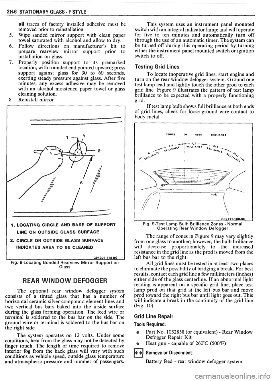
4. LOCATING CIRCLE AND BASE OF SUPPORT
LINE ON OUTSIDE GLASS SURFACE
2. CIRCLE ON OUTSIDE GLASS SURFACE
INDICATES AREA TO BE CLEANED
G94301-11 B.BG
Fig. 8-Locating Bonded earv view Mirror Support on
Glass
REAR WlMBOW DEFOGGER
The optional rear window defogger system
consists of a tinted glass that has a number of
horizontal ceramic silver compound element lines and
two vertical bus bars baked into the inside surface
during the glass forming operation. The feed wire or
terminal is soldered to the bus bar on the side. The
ground wire or terminal is soldered to the bus bar on
the right side.
The system operates on 12 volts. Under some
conditions, heat from the glass may not be detected by
finger touch. The length of time required to remove
interior fog from the back glass will vary with such
conditions as vehicle speed, outside glass temperature
and atmospheric pressure and number of passengers. This
system uses an instrument panel mounted
switch with an integral indicator lamp; and will operate
for five to ten minutes and automatically turn off
through the use of an automatic timer. The system can
be turned off during this operating period by turning
either the instrument panel mounted switch or ignition
switch to off.
Testing Grid Lines
To locate inoperative grid lines, start engine and
turn on the rear window defogger system. Ground one
test lamp lead and lightly touch the other prod to each
grid line. Figure
9 illustrates the pattern of test lamp
brilliance to be expected with a properly functioning
grid.
If test lamp bulb shows full brilliance at both ends
of grid lines, check for loose ground wire contact to
body metal.
Fig. 9-Test Lamp Bulb Brilliance Zones - Normal
Operating Rear Window Defogger
The range of zones in Figure 9 may vary slightly
from one glass to another; however, the bulb brilliance
will decrease proportionately to the increased
resistance in the grid line as the prod is moved from the
left bus bar to the right.
All grid lines must be tested in at least two places
to eliminate the possibility of bridging a break. For best
results, contact each grid line a few millimeters (inches)
either side of the glass centerline. If an abnormal light
reading is apparent on a specific grid line, place test
lamp prod on that grid at the left bus bar and move
prod toward the right bus bar until light goes out. This
will indicate a break in the continuity of the grid line
(Fig.
10).
Grid Line Repair
Tools Required:
o Part No. 1052858 (or equivalent) - Rear Window
Defogger Repair Kit
e Heat gun - capable of 260°C (500°F)
Remove or Disconnect
Battery 'feed - rear window defogger system
Page 1710 of 1825
FRONT END - F STYLE 41-1-1
SECTION 4H
FRONT END
NOTICE: The anti-theft label found on some major sheet metal, engines, and transmissions must be masked
prior to painting, rustproofing, undercoating, etc. The
mask must be removed following the above operations.
Failure to keep the label clean and readable may result in liability for violation of Federal Vehicle Theft Prevention
Standard, and subject the vehicle owner to possible suspicion that the part was stolen.
CONTENTS
.............................................................................................................. Body Ventilation 4H- 1
Shroud Side Trim Finishing Panel ................................................................................ 4H- 1
Pressure Relief Valve .................................................................................................. 4H- 1
Hood Latch Release Cable ............................................................................................ 4H- 1
The body ventilation system on styles without air
conditioning consists of a fresh air intake located at the
front plenum chamber. Air enters the front plenum
chamber through an air intake grille screen (Fig.
1).
Air passes through the plenum chamber to air outlet
doors. When ventilation controls are operated, air
enters past the doors and into the body from outlets in
the dash panel. The air then passes through the body,
around the rear seat, into the rear compartment to the
rear quarters and leaves the body passing through the
pressure relief valves on the rear body lock pillars (Fig.
4). For complete instructions on operation of the body
ventilation system, refer to the owner's manual.
Water entering the plenum chamber is drained
through openings provided for that purpose.
FRONT END SEALING
All potential waterleak locations are sealed in
production with high quality durable sealers. Should it
be necessary to reseal specific areas, a high quality
medium-bodied sealer which will remain flexible after
curing and can be painted should be used.
SHROUD SIDE TRIM FINISHING PANEL
Removal and Installation
1. Remove shroud side trim finishing panel screws
(Fig. 2).
2. Pull down and rearward on trim finishing panel
to release hood cable handle from slot on left side.
On right side, pull rearward to remove panel from
windshield lower side garnish (Figs.
2 and 3).
3. To install, reverse removal procedures.
PRESSURE RELIEF VALVE
The pressure relief valves are attached to rear
lock pillars (in door opening below belt) with screws.
Figure
4 shows pressure relief valve installations.
Removal and Installation
1. Remove louver-to-lock pillar screw located in the
door opening (Fig.
4).
2. Slide louver up to disengage hook-type attaching
clip to complete removal.
3. To install, reverse removal procedure.
HOOD LATCH RELEASE CABLE
The one-piece hood latch release cable includes
pull handle, control cable and housing. The control
cable is installed through the left shroud side trim
panel. A sealing grommet attached to the dash panel
completes the assembly (Figs. 2 and
5).
Removal and Installation
The shroud side finishing panels are designed
with an integral hinge pillar pinchweld finishing lace.
The left side has a cutout slot for the hood release cable
handle. There is no need to remove the cable assembly
2.
when removing the trim finishing panel. The trim 3.
finishing panel is secured to the side shroud with
self-tapping attaching screws.
4.
Raise hood and disengage cable from hood latch
assembly. Block latch to prevent hood locking
until cable has been reinstalled.
Remove left shroud side trim panel.
Disengage control assembly housing from cutout
of trim panel and remove
cable assembly from
panel.
To install, reverse the removal procedure.
Page 1817 of 1825
2 - CHASSIS INDEX
Backup Lamp Switch (Circuit) .......... 8A- 1 12. 7A 1-5
Backup Lights
..................................................... 8B-1
...................................................... Battery Section 6D 1
............................ Battery Specification Chart 6D 1-7
.................................... Body Identification ... .... OA- 1
Borg Warner Rear Axle .......................... Section 4B1
...................................................... Blower Motor 1A-14
Blower Switch
.................................................... 1 A- 13
Booster Assembly
............................................. 5D2-2
Brakes
- General ......................................... Section 5
Adjustment
.................................................... 5C3-4
Booster Assembly
. Tandem
Diaphragm
................... .... ..................... 5D2- 1
................................................ Components 5C3- 1
Diagnosis and Inspection
................................. 5-3
Disc Brake Caliper Assembly
.................................................... 3548 Series 5B6-1
Drum Brake Assembly ........................ Section 5C3
General Description
.......................................... 5-2
On-Car Service
.................................................... 5-7
Specifications & Special Tools ......................... .5 F. 1
...................................................... Unit Repair 5A3- 1
.......................................... Warning System 8A-4 1-0
............ Brake Pedal Mounting .. ......................... 5-1 7
Bulb Usage Chart
............................................ 8B-10
............................................ Bumpers Section 2B,3 D.6
Bumper Energy Absorbing Units
.................... 2B-2
Bench Testing
................................................ 2B-3
........................................ Damage/Leakage 2B-3
................................ Removal After Collision 2B-2
............................................. Fascia Rub Strips .2 B. 1
.................................................... Front Bumper 2B-2
Assembly
........................................................ 2B-4
Energy Absorber
........................................... 2B-4
............................................................. Fascia .2 B. 1
On-Vehicle Service
...................................... 2B-4
Rear Bumper
.................................... .... ............ 2B-2
........................................................ Assembly 2B-5
Energy Absorber
............................................ 2B-4
............. .................... Fascia Molding Strip .. 2B-5 ........................................... Service Procedures .2 B. 1
.................................................. Specifications 2B-5
C
Caliper Assembly . Disc Brake
.............................................. 3000/3 100 Series 5B 1-2
3548 Series
...................................................... 5B6-2
Caliper Overhaul
....................... 3000/3 100 Series .. ............... 5B 1-4
3548 Series
.................................................... 5B6-5
Caster and Camber Adjustment
........................ 3A- 1
............................................. Catalytic Converter 6F-2
Center High-Mounted Stoplight
....................... ... 8B- 1
Charging System
...................... 8A.30.7, Section 6D3
Chassis Electrical
.................................... Section 8B
Center High Mounted Stoplight
...................... 8B-1 ................................. Exterior Light Monitor .8 B. 1
................................................................ Chimes 8A-77
................................ Cigar Lighter (Circuit) 8A- 1
14-0
.............................. Circuit Breaker Details Section 8A
Power ACC Circuit Breaker .... 8A- 10.1.10.3.10.5.
11-3
.... Window Circuit Breaker 8A~10~1,10~3.10~5.1 1.4
Clutch
........................................................ Section 7C
......................................... General Description .7 C. 1 ........................................................... Diagnosis 7C-2 Bleeding
Hydraulic Clutch System
................. .7 C.2
Preliminary Checks ..................................... ... 7C-2
On-Vehicle Service
........................................... 7C-5
Clutch Hydraulic System
.................................. 7C-5
Clutch Pedal ...................................................... 7C-6
Pilot Bearing
..................................................... 7C-6
Pressure Plate and Disc
.................................... 7C-6
Special Tools
......................... ....... ................ 7C-8
Specifications
................................................... 7C-8
Coil Springs and Insulators .............................. 3D-1
Component Fluid Capacities
................................ OB-6
Component Location Views
........................ 8A-201-0
Composite Master Cylinder
................... Section 5A3
Compression Test
.................. .. ............................. 6-5
Condenser Mounting
....................................... 1B 1-24
Connectors
.................................................... 8A-202-0
Coolant Fan Temperature Switch
...................... 8A-3 1
Cooling and Radiator
................................ Section 6B
Cooling System Capacities
................................. OB-6
Cooling System Diagnosis
.................................... 6B-3
Cranking System
...................................... Section 6P*
Diagnosis ..................................................... 6~2
General Description ................................ 6D2- 1
Cranking System
........................................ 6D2- 1
Solenoid
................................................... 6D2- 1
Starter Motor ......................................... 6D2-1
On-Vehcile Service
...................................... 6D2-4
Specifications
............................................ 6D2- 1
Starter
........................................................ 6D2-4
Unit Repair
............................................ 6D2-6- 11
Service Procedures
...................................... 6D2-3
Cruise Control
.............................. 8A-34-0, Section 9B
Diagnosis
............................................................ 9B-4
Cruise Set Speed High or Low
.................... 9B-4
Cruise System Surges
.................................. 9B-4
Cruise Tap-Up and Tap-Down
...................... 9B-4
Excessive Cruise Speed Loss on
Hills
........................................................... 9B-4
General Description
........................................ 9B-1
Electrical and Vacuum Release
Switches
...................................................... 9B-4
Electrical Harness
.......................................... 9B-A
Electronic Controller (Module) .................... 9B .
Off/On/Resume/Accel Switch
Operation
.................................................. .91 B-
Servo Unit
.................................................... 9B-2
Set/Coast Button Switch .............................. 9B-1
................................................ Speed Sensors 9B-3
Vacuum Supply
............................................ 9B-4
On-Car Service
.................................................. 9B-6
................................ Cruise Release Switches 9B-6
.......................................... Servo Mounting 9B-10
Vacuum Harness and Cable Routing
VIN
E ................................. .. .................. 9B,7
.................................................... VIN F, 8 9B-9
....................................................... VIN S 9B-8
........................ Vacuum Tank - VIN S,F,E, 9B-10
.............................. Cruise Control (Circuit) 8A-34-0
D
......................................... Defogger (Circuit) $A-6 1-0
..................... ...... Defroster Duct Assembly ... .812 C-
Diagnosis
Air Conditioning
- General ........................... 1B-5
.................... Automatic Transmission - General 7A
Automatic Transmission
- ................ HD-700-R4-2
Page 1818 of 1825
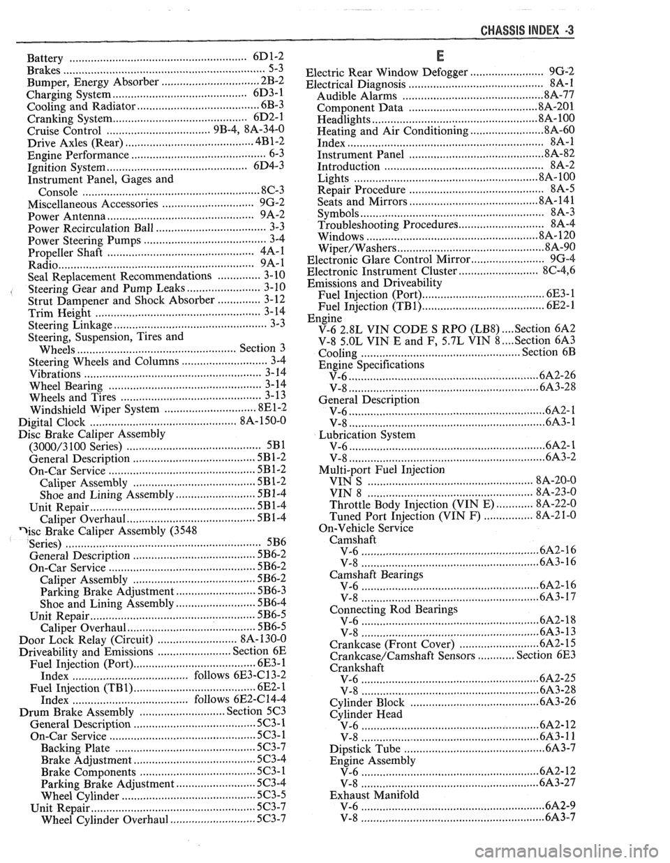
Battery .......................................................... 6D1-2
Brakes
.................................................................. 5-3
................................ Bumper. Energy Absorber 2B-2
........................................... Charging System 6D3- 1
........................................ Cooling and Radiator 6B-3
....................... ................ Cranking System .. 6D2- 1
Cruise Control
................................. 9B-4, 8A-34-0
......................................... Drive Axles (Rear) 4B1-2
Engine Performance
......................................... 6-3
.............................................. Ignition System 6D4-3
Instrument Panel, Gages and
.................................................... Console 8C-3
............................. Miscellaneous Accessories 9G-2
............................................... Power Antenna 9A-2
Power Recirculation Ball
.................................. 3-3
Power Steering Pumps
........................................ 3-4
.............................................. Propeller Shaft 4A- 1
................................................................ Radio 9A-1
.............. Seal Replacement Recommendations 3- 10
........................ . Steering Gear and Pump Leaks 3-10
.............. Strut Dampener and Shock Absorber 3- 12
.................................................... Trim
Height 3- 14
.................................................. Steering Linkage 3-3
Steering, Suspension, Tires and
Wheels
.............................. .. ................. Section 3
Steering Wheels and Columns
............................ 3-4 ......................................................... Vibrations 3- 14
................................................. Wheel Bearing 3-14 .............................................. Wheels and Tires 3- 13
........................... Windshield Wiper System 8El-2
............................................. Digital Cloclc 8A- 150-0
Disc Brake Caliper Assembly
.......................................... (3000/3 100 Series) 5B1
............... ................... General Description .. 5B 1-2 ............................................... On-Car Service 5B 1-2
...................................... Caliper Assembly 5B 1-2
.......................... Shoe and Lining Assembly 5B 1-4
...................................................... Unit Repair
5B 1-4
.......................................... Caliper Overhaul 5B 1-4
?isc Brake Caliper Assembly (3548
Series)
............................................................. 5B6
General Description
....................................... 5B6-2
On-Car Service
............................................... 5B6-2
....................................... Caliper Assembly 5B6-2
.......................... Parking Brake Adjustment 5B6-3
.......................... Shoe and Lining Assembly 5B6-4
Unit Repair
............................... ... .................... 5B6-5
Caliper Overhaul
.......................................... 5B6-5
.......................... Door Lock Relay (Circuit) 8A- 130-0
Driveability and Emissions
........................ Section 6E
Fuel Injection (Port)
..................................... 6E3-1
Index
................................... follows 6E3-(213-2
...................................... Fuel Injection (TB 1) .6E
2- 1
...................................... Index follows 6E2-C 14-4
Drum Brake Assembly
................... ......... Section 5C3
General Description
......................... ... ............ 5C3-1
........................................... On-Car Service 5C3- 1
Backing Plate
........................................ 5C3-7
....................................... Brake Adjustment .5C 3-4
..................................... Brake Components 5C3-1
Parking Brake Adjustment
.......................... 5C3-4
Wheel Cylinder ........................................... 5C3-5 ..................................................... Unit Repair 5C3-7
............................ Wheel Cylinder Overhaul 5C3-7
CHASSIS INDEX m3
E
........................ Electric Rear Window Defogger 9G-2 ............................................ Electrical Diagnosis 88-1
Audible Alarms .............................................. 81%-77
.......................................... Component Data 818-201
.................................................... Headlights 8A- 100
........................ Heating and Air Conditioning 8A-60 .............................................................. Index $A- 1
........................................... Instrument Panel .8 A-82
.................................................. Introduction 8A-2
........................................................... Lights .8 A- 100
............................................ Repair Procedure 88-5 ........................................ Seats and Mirrors 8A- 141
......................................................... Symbols 8A-3
Troubleshooting Procedures ............................ 8A-4
.................................................. ... Windows .. .8 A- 120
............................................... Wiper/Washers .8 A-90
Electronic Glare Control Mirror
........................ 9G-4
.......................... Electronic Instrument Cluster 86-4, 6
Emissions and Driveability
....................................... Fuel Injection (Port) 6E3- 1
....................................... Fuel Injection (TB1) 6E2-1
Engine
.... V-6 2.8L VIN CODE S RPO (LB8) Section 6A2
.... V-8 5.OL VIN E and F, 5.7L VIN 8 Section 6A3
................................................. Cooling Section 6B
Engine Specifications
............................................................ V-6 6A2-26
............................................................. V-8 683-28
General Description
.............................................................. V-6 61 ............................................................. V-8 6A3-1
Lubrication System ........................................................... V-6 ..6A 2- 1
................................................................ V-8 6A3-2
Multi-port Fuel Injection
..................................................... VIN S 8A-20-0
................................................. VIN 8 8A-23-0
............ Throttle Body Injection (VIN E) 8A-22-0
................ Tuned Port Injection (VIN F) 8A-2 1-0
On-Vehicle Service Camshaft
......................................................... V-6 6A2-16
................................ ..................... V-8 .. 6A3-16
Camshaft Bearings
......................................................... V-6 6A2-16
...................................................... V-8 ..6A 3-17
Connecting Rod Bearings
......................................................... V-6 .6A 2- 18
................................................... V-8 6A3-13
...................... Crankcase (Front Cover) .6A
2- 15
............ Crankcase/Camshaft Sensors Section 6E3
Crankshaft
....................................................... V-6 6A2-25
......................................................... V-8 .6A 3-28
......................................... Cylinder Block .6A 3-26
Cylinder Head
.......................................................... V-6 682-12
.......................................................... V-8 6A3-11
Dipstick Tube .............................................. 6A3-7
Engine Assembly
....................................................... V-6 6212
.......................................................... V-8 6A3-27
Exhaust Manifold
........................................................ V-6 .6A 2-9
V-8
....................................................... 6A3-7
Page 1821 of 1825
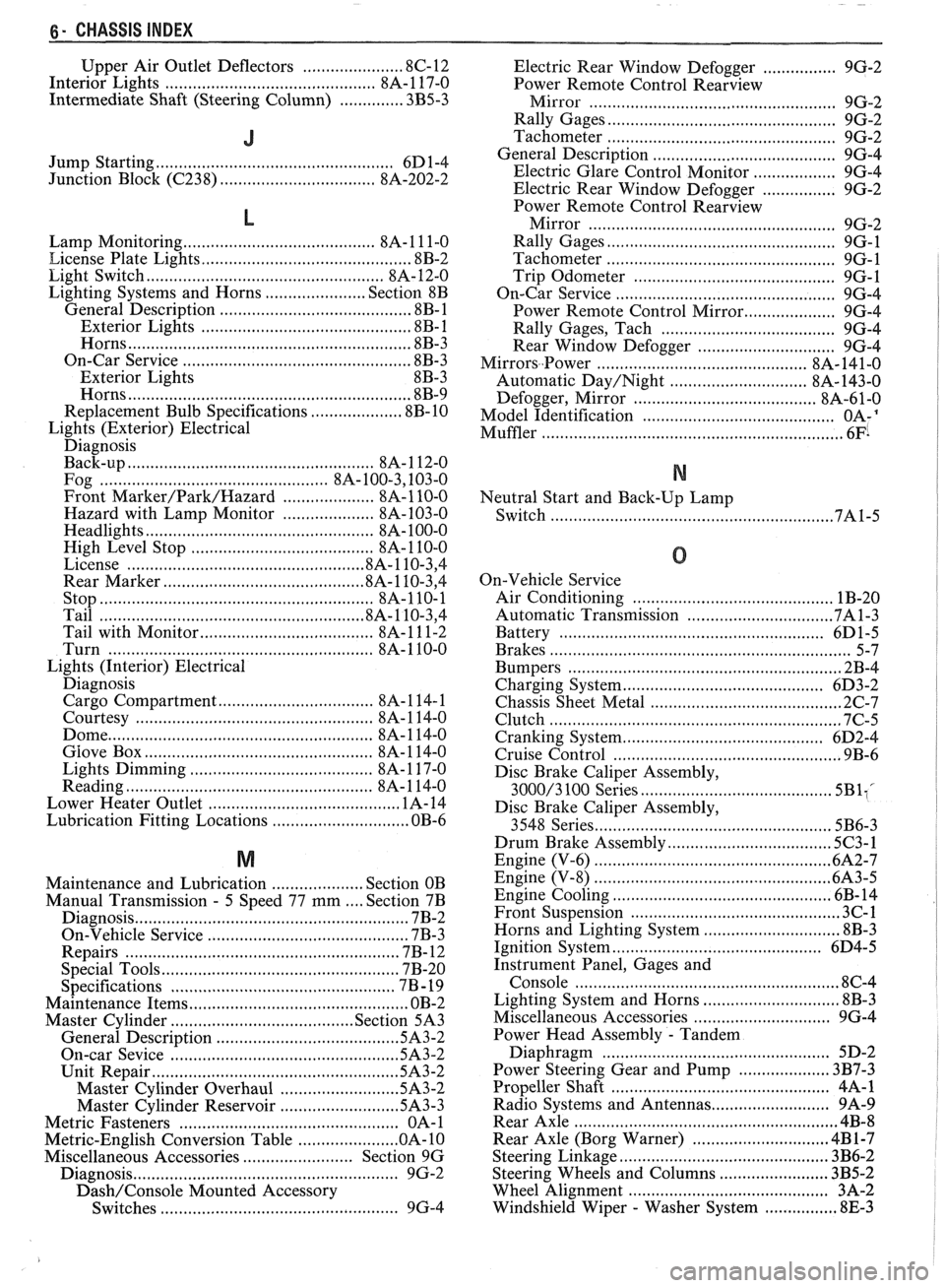
6- CHASSIS INDEX
Upper Air Outlet Deflectors ...................... 8C-12
Interior Lights ............................................. 8A- 1 17-0
Intermediate Shaft (Steering Column)
.............. 3B5-3
J
Jump Starting .................................................... 6D 1-4
Junction Block
((2238) ................................. 8A-202-2
L
Lamp Monitoring ......................................... 8A- 1 1 1-0
License Plate Lights .............................................. 8B-2
Light Switch
.................................................... 8A- 12-0
Lighting Systems and Horns
...................... Section 8B
General Description ......................................... .8 B- 1
Exterior Lights
............................................ 8B- 1
Horns ....................... .. ................................. 8B-3
On-Car Service
.................................................. 8B-3
Exterior Lights 8B-3
Horns
.............................................................. 8B-9
Replacement Bulb Specifications .................... 8B-10
Lights (Exterior) Electrical Diagnosis
Back-up
...................................................... 8A- 1 12-0
Fog ............................................... 8A- 100.3,10 3.0
Front
Marker/Park/Hazard .................... 8A-110-0
Hazard with Lamp Monitor .................... 8A-103-0
Headlights .................................................. 8A- 100-0
High Level Stop
..................................... 8A-110-0
License .................................................. .8A.110.3, 4
Rear Marker
........................................... .8 A. 1 10.3, 4
Stop ........................................................... 8A-110-1
Tail ......................................................... .8 A. 1 10.3, 4
Tail with Monitor
................ .... ........... 8A- 1 1 1-2
Turn
......................................................... 8A- 1 10-0
Lights (Interior) Electrical
Diagnosis Cargo Compartment
............................. 8A- 1 14- 1
Courtesy
................................................. 8A- 1 14-0
Dome
.................................. .. ...................... 8A- 1 14-0
Glove Box .................................................. 8A- 1 14-0
Lights Dimming
...................................... 8A- 1 17-0
Reading
...................................................... 8A- 1 14-0
Lower Heater Outlet
........................................ 1A-14
Lubrication Fitting Locations .............................. OB-6
M
Maintenance and Lubrication .................... Section OB
Manual Transmission
. 5 Speed 77 mm .... Section 7B
Diagnosis
........... .. ............................................ 7B-2
On-Vehicle Service
.......................................... 7B-3
Repairs
................................... .... .................... 7B- 12
Special Tools
................................................. 7B-20
. Specifications .............................................. 7B 19
Maintenance Items
................................................ OB-2
Master Cylinder
........................................ Section 5A3
General Description
...................................... ..5A 3.2
On-car Sevice
................................................ 5A3-2
Unit Repair ..................................................... .5A 3.2
Master Cylinder Overhaul
......................... .5A 3.2
Master Cylinder Reservoir
......................... .5A 3.3
Metric Fasteners
................................................ OA- 1
Metric-English Conversion Table ..................... .O A. 10
Miscellaneous Accessories
........................ Section 9G
Diagnosis
.......................................................... 9G-2
Dash/Console Mounted Accessory
Switches
.................................................... 9G-4 Electric
Rear Window Defogger
................ 9G-2
Power Remote Control
Rearview
......................... Mirror ...................... .. 9G-2
Rally Gages
................................................. 9G-2
Tachometer
.................................................. 9G-2
..................................... General Description 9G-4
Electric Glare Control Monitor
.................. 9G-4
Electric Rear Window Defogger
................ 9G-2
Power Remote Control
Rearview
Mirror ..................................................... 9G-2
Rally Gages
................................................. 9G-1
Tachometer
................................................. 9G-1
Trip Odometer
............................................ 9G-1
............................................. On-Car Service 9G-4
Power Remote Control Mirror
.................... 9G-4
Rally Gages. Tach
..................................... 9G-4
Rear Window Defogger
.............................. 9G-4
Mirrors..Power ............................................ 8A- 141-0
Automatic
Day/Night ............................. 8A- 143-0
..................................... Defogger. Mirror 8A-61-0
.......................................... Model Identification OA-'
Muffler ................................................................. 6Fi
N
Neutral Start and Back-Up Lamp
Switch
...................................... ..
0
On-Vehicle Service
Air Conditioning
.................................... ... . 1B-20
Automatic Transmission
............................... .7A 1.3
Battery
........................................................ 6D1-5
................................ ......................... Brakes ... 5-7
Bumpers
......................................................... 2B-4
Charging System
.............................. ... ........... 6D3-2
Chassis Sheet Metal
.......................................... 2C-7
Clutch
................................................................ 7C-5
Cranking System
............................................ 6D2-4
Cruise Control ............................................... 9B-6
Disc Brake Caliper Assembly,
3000/3 100 Series .......................................... 5BliC
Disc Brake Caliper Assembly,
3548 Series
................................................... 5B6-3
Drum Brake Assembly .................................... 5C3-1
Engine (V-6) .................................................... 6A2-7
Engine (V-8) ................................................ -6A3-5
Engine Cooling ....................................... .. .... 6B- 14
Front Suspension
........................................... 3C-1
Horns and Lighting System .............................. 8B-3
Ignition System
.............................................. 6D4-5
Instrument Panel, Gages and
Console
.......................................................... 8C-4
Lighting System and Horns
.......................... .... 8B-3
Miscellaneous Accessories
.......................... .... 9G-4
Power Head Assembly
. Tandem
Diaphragm
................................................. 5D-2
Power Steering Gear and Pump
.................... 3B7-3
Propeller Shaft
............................................. 4A-1
.......................... Radio Systems and Antennas 9A-9
Rear Axle
.......................................................... 4B-8
Rear Axle (Borg Warner)
........................... ... 4B 1-7
Steering Linkage ............................................. 3B6-2
........................ Steering Wheels and Columns 3B5-2
Wheel Alignment
......................................... 3A-2
Windshield Wiper
- Washer System ................ 8E-3
Page 1823 of 1825
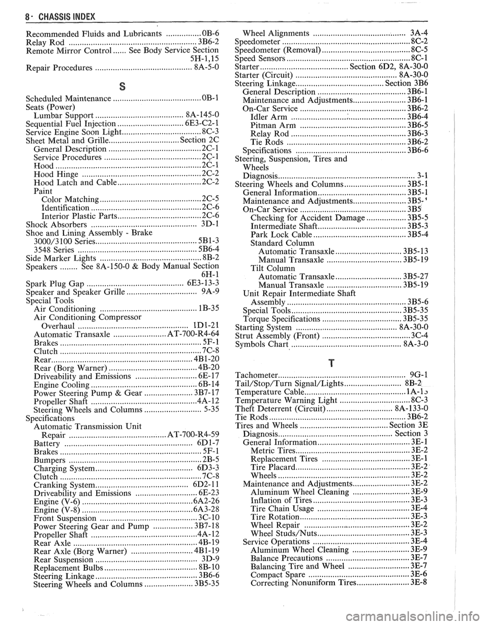
8- CHASSIS INDEX
Recommended Fluids and Lubricants ................ OB-6
Relay Rod
......................................................... 3B6-2
Remote Mirror Control
...... See Body Service Section
5H.1. 15
Repair Procedures
.......................................... 88-50
S
........................................ Scheduled Maintenance OB- 1
Seats (Power) ....................................... Lumbar Support 8A- 145-0
............................. Sequential Fuel Injection 6E3-C2- 1
Service Engine Soon Light
.................................... 8C-3
Sheet Metal and Grille
................................ Section 2C
......................................... General Description .2 C. 1
........................................... Service Procedures .2 C. 1
................................................................. Hood .2 C. 1
...................................................... Hood Hinge 2C-2
Hood Latch and Cable
...................................... 2C-2
Paint
.............................................. Color Matching 2C-5
................................................ Identification -32-6
Interior Plastic Parts ...................................... 2C-6
................................................ Shock Absorbers 3D-
1
Shoe and Lining Assembly
. Brake
............................................ 3000/3 100 Series 5B1-3
3548 Series ...................................................... 5B6-4
Side Marker Lights
.............................................. 8B-2
........ Speakers See 8A- 150-0 & Body
Manual Section
6H- 1
.................... Spark Plug Gap .. .................. 6E3-13-3
................................ Speaker and Speaker Grille 9A-9
Special Tools
............................................ Air Conditioning 1 B-3 5
Air Conditioning Compressor
................................................. Overhaul 1D1-21
........................ Automatic Transaxle AT-700-R4-64
................................................................ Brakes SF-1
Clutch ................................................................ 7C-8
................................................................ Rear 4B1-20
....................................... Rear (Borg Warner) 4B-20
........................... Driveability and Emissions .6 E. 17
................................................ Engine Cooling 6B- 14
Power Steering Pump
& Gear ...................... 3B7-17
............................................... Propeller Shaft .4 A. 12
Steering Wheels and Columns
.......................... 5-35
Specifications Automatic Transmission Unit
............................................ Repair AT-700-R4-59
..................................................... Battery 6D 1-7
................................................................ Brakes 5F-1
Bumpers
......................................................... 2B-5
Charging System
................ .. ................... 6D3-3
.............................................................. Clutch .7 (2.8
....................................... Cranking System 6D2- 1 1
Driveability and Emissions ............................ 6E-23
................................................ Engine (V-6) ..6A 2.26
Engine (V-8) .................................................. 683-28
........................................ Front Suspension 3C- 10
Power Steering Gear and Pump
.................. 3B7-18 ............................................. Propeller Shaft .4 A. 12 ........................................................ Rear Axle 4B-19 ............................ Rear Axle (Borg Warner) 4B 1- 19
Rear Suspension
.............................................. 3D-9
.......................................... Replacement Bulbs 8Br 10 .............................................. Steering Linkage 3B6-6
Steering Wheels and Columns
...................... 3B5-35
........................................ Wheel Alignments 3A-4
....................................................... Speedometer 8C-2
........................................ Speedometer (Removal) 8C-5
...................................................... Speed Sensors 8C-1
Starter ........................................ Section 6D2. 8A-30-0
............................................. Starter (Circuit) 8A-30-0
Steering Linkage ...................................... Section 3B6
....................................... General Description 3B6-1
........................ Maintenance and Adjustments 3B6-1
................................................ On-Car Service 3B6-2
..................................................... Idler Arm 3B6-4
................................................ Pitman Arm 3B6-5
.................................................... Relay Rod 3B6-3
Tie Rods
...................................................... 3B6-2
.................................................. Specifications 3B6-6
Steering, Suspension, Tires and
Wheels Diagnosis
............................................................. 3-1
Steering Wheels and Columns
............................ 3B5-1
..................................... General Information 3B5- 1
Maintenance and Adjustments
...................... 3B5-'
On-Car Service .............................. .. ........... 3B5
Checking for Accident Damage
.................. 3B5-5
Intermediate Shaft ............... .. .................... 3B5-3
Park Lock Cable .......................................... 3B5-4
Standard Column
............................. Automatic Transaxle 3B5-13
Manual Transaxle ................................. 3B5- 19
Tilt Column
.............................. Automatic Transaxle 3B5-27
.................................. Manual Transaxle 3B5-19
Unit Repair Intermediate Shaft
...................................................... Assembly 3B5-6
................................................. Special Tools 3B5-35
Torque Specifications
.................................... 3B5-35
............................................. Starting System 8A-30-0
........................................ Strut Assembly (Front) 3C-4
.................................... ..... Symbols Chart ... 8A-3-0
T
.......................................................... Tachometer 9G-1
Tail/Stop/Turn Signal/Lights .......................... 8B-2
Temperature Cable
.............................................. 112 A-
Temperature Warning Light ................................ 8C-3
Theft Deterrent (Circuit)
.............................. 8A-133-0
Tie Rods
.............................................................. 3B6-2
Tires and Wheels
........................................ Section 3E
Diagnosis
.................................................. Section 3
General Information
......................................... 3E-1
................................................... Metric Tires 3E-2
....................................... Replacement Tires .31 E-
.................................................... Tire Placard 3E-2
........................................................... Wheels 3E-2
Maintenance and Adjustments
.......................... 3E-2
.......................... Aluminum Wheel Cleaning 3E-9
............................. ......... Inflation of Tires .. 3E-3
........................................ Tire Chain Usage 3E-4
.................................................. Tire Rotation 3E-3
.............................................. Wheel Repair 3E-2
...................................... Wheel Studs/Nuts 3E-3
........................................... Service Operations 3E-4
........................ Aluminum Wheel Cleaning 3E-9
.................................... Balance Precautions 3E-7
............................ Balancing Tire and Wheel 3E-7
.............................................. Compact Spare 3E-6
........................ Correcting Nonuniform Tires 3E-8