1988 PONTIAC FIERO torque
[x] Cancel search: torquePage 102 of 1825
BUMPERS 28-1
SECTION 2B
BUMPERS
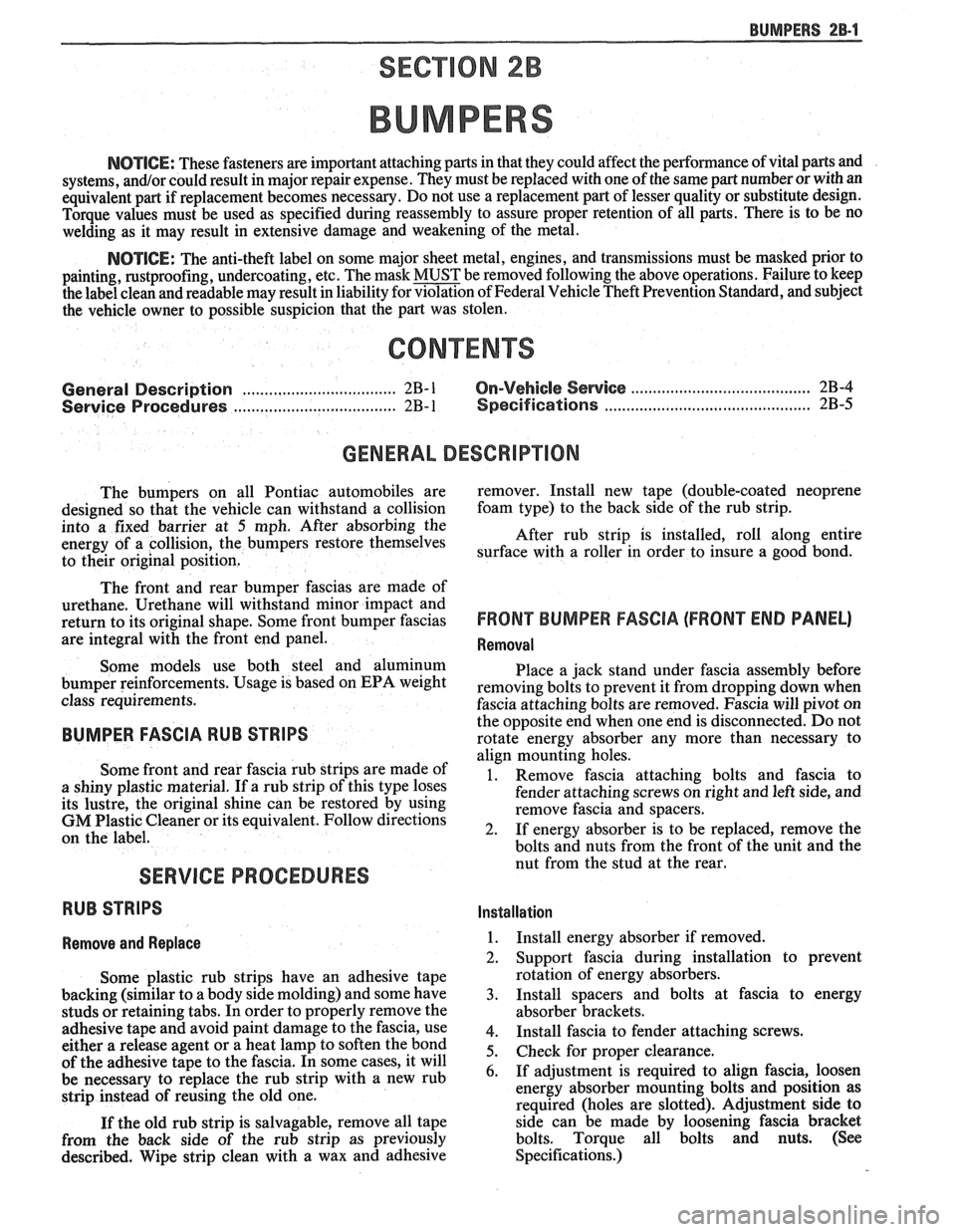
NOTICE: These fasteners are important attaching parts in that they could affect the performance of vital parts and
systems,
andlor could result in major repair expense. They must be replaced with one of the same part number or with an
equivalent
part if replacement becomes necessary. Do not use a replacement part of lesser quality or substitute design.
Torque values must be used as specified during reassembly to assure proper retention of all parts. There is to be no
welding as it may result in extensive damage and weakening of the metal.
NOTICE: The anti-theft label on some major sheet metal, engines, and transmissions must be masked prior to
painting, rustproofing, undercoating, etc. The mask MUST be removed following the above operations. Failure to keep
the label clean and readable may result in liability for violation of Federal Vehicle Theft Prevention Standard, and subject
the vehicle owner to possible suspicion that the part was stolen.
CONTENTS
General Description ................................ 2B-1 On-Vehicle Service ..................................... 2B-4
........................................... ..................... Service Procedures .. ........... 2B- 1 Specifications 2B-5
GENERAL DESCRIPWIBN
The bumpers on all Pontiac automobiles are remover.
Install new tape (double-coated neoprene
designed so that the vehicle can withstand a collision foam type)
to the back side of the rub strip.
into a fixed barrier at
5 mph. After absorbing the
energy of a collision, the bumpers restore themselves After
rub strip is installed, roll along entire
to their original position. surface with a roller
in order to insure a good bond.
The front and rear bumper fascias are made of
urethane. Urethane will withstand minor impact and
return to its original shape. Some front bumper fascias
are integral with the front end panel.
Some models use both steel and aluminum
bumper reinforcements. Usage is based on
EPA weight
class requirements.
BUMPER FASCIA RUB STRIPS
Some front and rear fascia rub strips are made of
a shiny plastic material. If a rub strip of this type loses
its lustre, the original shine can be restored by using
GM Plastic Cleaner or its equivalent. Follow directions
on the label.
SERVICE PROCEDURES
RUB STRIPS
Remove and Replace
Some plastic rub strips have an adhesive tape
backing (similar to a body side molding) and some have
studs or retaining tabs. In order to properly remove the
adhesive tape and avoid paint damage to the fascia, use
either a release agent or a heat lamp to soften the bond
of the adhesive tape to the fascia. In some cases, it will
be necessary to replace the rub strip with a new rub
strip instead of reusing the old one.
If the old rub strip is salvagable, remove all tape
from the back side of the rub strip as previously
described. Wipe strip clean with a wax and adhesive
FRONT BUMPER FASCIA (FRONT END PANEL)
Removal
Place a jack stand under fascia assembly before
removing bolts to prevent it from dropping down when
fascia attaching bolts are removed. Fascia will pivot on
the opposite end when one end is disconnected. Do not
rotate energy absorber any more than necessary to
align mounting holes.
1. Remove fascia attaching bolts and fascia to
fender attaching screws on right and left side, and
remove fascia and spacers.
2. If energy absorber is to be replaced, remove the
bolts and nuts from the front of the unit and the
nut from the stud at the rear.
Installation
1. Install energy absorber if removed.
2. Support fascia during installation to prevent
rotation of energy absorbers.
3. Install spacers and bolts at fascia to energy
absorber brackets.
4. Install fascia to fender attaching screws.
5. Check for proper clearance.
6. If adjustment is required to align fascia, loosen
energy absorber mounting bolts and position as
required (holes are slotted). Adjustment side to
side can be made by loosening fascia bracket
bolts. Torque all bolts and nuts. (See
Specifications.)
Page 103 of 1825
2B-2 BUMPERS
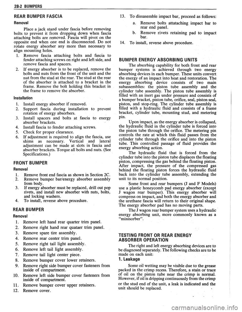
REAR BUMPER FASCIA
Removal
Place a jack stand under fascia before removing
bolts to prevent it from dropping down when fascia
attaching bolts are removed. Fascia will pivot on the
opposite end when one end is disconnected. Do not
rotate energy absorber any more than necessary to
align mounting holes.
1. Remove fascia attaching bolts and fascia to
fender attaching screws on right and left side, and
remove fascia and spacers.
2. If energy absorber is to be replaced, remove the
bolts and nuts from the front of the unit and the
nut from the stud at the rear. The stud at the rear
of the absorber is attached to a bracket in the
frame. Remove the bolt holding this bracket in
the frame to remove the absorber.
Installation
1. Install energy absorber if removed.
2. Support fascia during installation to prevent
rotation of energy absorbers.
3. Install spacers and bolts at fascia to energy
absorber brackets.
4. Install fascia to fender attaching screws.
5. Check for proper clearance.
6. If adjustment is required to align the fascia, use
shims as necessary. Vertical and lateral
adjustment can be made at slots in fascia and
absorber brackets. Torque all bolts and nuts. (See
Specifications.)
FRONT BUMPER
Removal
1. Remove
front end fascia as shown in Section 2C.
2. Remove bumper barlenergy absorber assembly
from body.
3. If energy absorber must be replaced, drill out pop
rivets, and install new absorber with nuts, bolts,
and locking washers.
4. To install, reverse above procedure.
REAR BUMPER
Removal
1. Remove left hand rear quarter trim panel.
2. Remove right hand rear quataer trim panel.
3. Remove spare tire assembly.
4. Remove rear center trim panel.
5. Remove right tail light assembly.
6. Remove left tail light assembly.
7. Remove tail light center piece.
8. Remove bumper cover lower retainers.
9. Remove right-side bumper cover fasteners from
inside of compartment.
10. Remove left side bumper cover fasteners from
inside of compartment.
11. Remove bumper cover upper retainers.
12. Remove cover.
13. To dissasemble impact bar, proceed as follows:
a. Remove bolts attataching impact bar to
rear end panel.
b. Remove rivets retaining pad to impact
bar.
14. To install, reverse above procedure.
BUMPER ENERGY ABSORBING UNITS
The absorbing capability for both front and rear
bumper systems is achieved through two energy
absorbing devices in each bumper. These units convert
the energy of an impact into heat and restoration. The
energy absorbing device consists of two main
subassemblies: the piston tube assembly and the
cylinder tube assembly. The piston tube assembly is
filled with an inert gas under pressure and consists of
a bumper bracket, piston tube, orifice, seal, piston seal,
piston, and stop-ring. The cylinder tube assembly is
filled with a hydraulic fluid and consists of a frame
bracket, cylinder tube, mounting stud, and metering
pin.
Upon impact, as the energy absorber is collapsed,
the hydraulic fluid in the cylinder tube is forced into
the piston tube through the orifice. The metering pin
controls the rate at which this fluid passes from the
cylinder tube through the orifice and into the piston
tube. This controlled passage of fluid provides the
energy absorbing action.
The hydraulic fluid that is forced from the
cylinder tube into the piston tube displaces the floating
piston, compressing the gas behind the floating piston.
After impact, the pressure of the compressed gas
behind the floating piston forces the hydraulic fluid
back into the cylinder tube assembly, extending the
unit to its normal position.
Some front and rear bumpers (J and
F Models)
use a plastic honeycomb pad energy absorber (except
J wagon rear bumper). This energy absorber will
compress on impact, and both the energy absorber and
the urethane fascia will return to their original shape.
The energy absorber pad has no moving parts.
The J wagon rear bumper system uses a hydraulic
energy absorbing unit, more commonly known as a
"minisorber".
TESTING FRONT OR REAR ENERGY
ABSORBER OPERATION
The right and left energy absorbing devices are to
be diagnosed separately. The following checks are to be
made on each unit:
1. Leakage
Some oil wetting may be visible due to the grease
packed in the crimp recess. Therefore, a stain or trace
of oil on the piston tube near the crimp is normal.
However, if oil is dripping continuously from the crimp
or the stud end of the unit, a leak is indicated and the
unit should be replaced.
Page 106 of 1825
BUMPERS 28.5
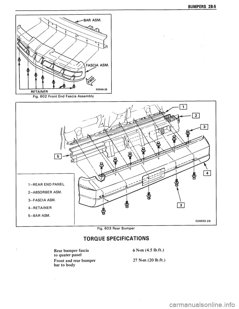
TORQUE SPECIFICATIONS
Rear bumper fascia
to quater
pailel
Front and rear bumper
bar to body
Page 108 of 1825
CHASSIS SHEET METAL 2C-1
SECTION %C
CHASS S SHEET METAL
NOTICE: These fasteners are important attaching parts in that they could affect the performance of vital
parts and systems,
andlor could result in major repair expense. They must be replaced with one of the same part
number or with an equivalent part if replacement becomes necessary. Do not use a replacement part of lesser
quality or substitute design. Torque values must be used as specified during reassembly to assure proper retention
of all parts. There is to be no welding as it may result in extensive damage and weakening of the metal.
For prevailing torque
nut(s) and bolt(s), refer to the "Reuse of Prevailing Torque Nut(s) and Bolt(s)" chart in
Section OA.
CONTENTS
............................... General Description 2C-1
.............................................. Fasteners 2C- I
.......................... Anti-Corrosion Materials 2C- 1
................................ Service Procedures 2C-1
..................................... Hood Assembly 2C-1
.......................................... Hood Hinge 2C-2
........................................... Hood Latch 2C-2
......................................... Fender Panel 2C-3
.............................. Molding Replacement 2C-3
Aluminum Panel Repair Procedures
............. 2C-3
PaintingIRepairing Non-Metal Parts ............. 2C-3
RepairingIRefinishing Urethane
Bumpers and Front End Panels
................. 2C-4
.............................. Paint Color Matching 2C-5
Proper Identification and Painting of
............................. Interior Plastic Trim.. 2C-6
....................................... Test Procedure 2C-6
Painting Interior Plastic Parts
..................... 2C-6
...................... Polypropylene Plastic Parts .2C-6
Rigid or Hard Plastic Parts ....................... 2C-7
Vinyl and Flexible ABS Parts
.................... 2C-7
On-Vehicle Sewice ................................ 2C-7
GENERAL DESCRIPTION
FASTENERS SERVICE PROCEDURES
Many aluminum components are used in the
current models. Aluminum in contact with steel may
corrode rapidly if not protected by means of special
finishes or isolators.
Many of the fasteners used in the front sheet
metal area have the new GM
6174M finish which will
provide adequate protection. In some places, how-
ever, special fasteners are used in conjunction with
aluminum components. These special fasteners are
argent silver in order to more easily identify them
from the standard metric fasteners which are a
medium blue in color.
When replacing fasteners in the front sheet
metal area, it is advisable to avoid substitution of
otherwise similar fasteners in locations which should
use GM
6174M type fasteners or special fasteners for
aluminum components.
NOTICE: Failure to follow this precaution may
result in premature corrosion of the sheet metal in
the areas mentioned above.
ANTI-CORROSION MATERIALS
Anti-corrosion materials have been applied to
the interior surfaces of some metal panels to provide
rust resistance. When servicing these panels, areas on
which these materials have been disturbed should be
properly
recoated with service-type anti-corrosion
material.
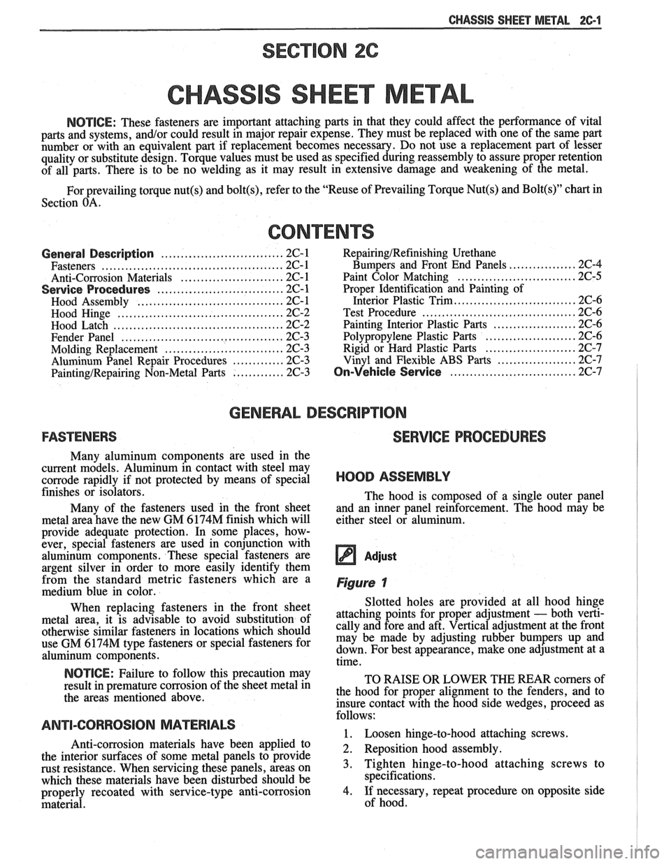
HOOD ASSEMBLY
The hood is composed of a single outer panel
and an inner panel reinforcement. The hood may be
either steel or aluminum.
Adjust
Figure 1
Slotted holes are provided at all hood hinge
attaching points for proper adjustment
- both verti-
cally and fore and aft. Vertical adjustment at the front
may be made by adjusting rubber bumpers up and
down. For best appearance, make one adjustment at a
time.
TO RAISE OR LOWER THE REAR comers of
the hood for proper alignment to the fenders, and to
insure contact with the hood side wedges, proceed as
follows:
1. Loosen hinge-to-hood attaching screws.
2. Reposition hood assembly.
3. Tighten hinge-to-hood attaching screws to
specifications.
4. If necessary, repeat procedure on opposite side
of hood.
Page 135 of 1825

3-10 STEERING, SUSPENSION, TIRES AND WHEELS DIAGNOSIS
Reminder Keeps Operating With Key In Lock
Cylinder, Driver's Door Open Or Closed; Ceases
When Key Is Removed
Inspect
s Door jamb switch on driver's side misadjusted or
inoperative.
e Wire from signal switch to door jamb switch
shorted.
A. This condition indicates the lock cylinder or
the reminder switch is at fault. To verify,
check for continuity at the
"E" and "F"
male column connector contacts, with the
key removed from the lock cylinder. If
continuity exists, the fault is in the column.
B. Insert the key into the lock, then turn the
lock toward the "Start" position. If the
reminder stops when the key is in the
"Run" position or when it is turned past
"Run" toward "Start," the problem is a
sticky lock cylinder actuator.
COLUMN-MOUNTED DIMMER SWITCH
No "Low" or "High" Beam
Inspect
e Loose connector at dimmer switch
e Improper adjustment
e Internally damaged or worn switch. Check the
continuity on the switch at the It. green and at the
tan switch terminals by pushing in the plunger all
the way.
A click should be heard. If there is no
continuity, replace the dimmer switch. If there is
continuity, refer
to'section 8A for electricaldiag-
nosis.
PIVOT AND SWITCH ASSEMBLY
Switch Inoperative: No "Low," "High" and/or
"Wash"
e Loose body-to-switch connector
a Broken or damaged switch
Internally damaged or worn switch. Connect a
new switch without removing the old one. If the
system functions, replace the switch. If the
system doesn't function, refer to Section
8A for
electrical diagnosis.
STEERING GEAR AND PUMP LEAKS
General Procedure
Inspect
s Overfilled reservoir
s Fluid aeration and overflow
e , Hose connections
Verify exact point of leakage Example:
Torsion bar, stub shaft and
adjuster seals are close together; the exact
spot where the system is leaking may not be
clear.
Example: The point from which the fluid is
dripping is not necessarily the point where
the system is leaking; fluid overflowing from
the reservoir, for instance.
e When service is required:
A. Clean leakage area upon disassembly.
B. Replace leaking seal.
C. Check component sealing surfaces for
damage.
D. Reset bolt torque to specifications, where
required.
Some complaints about the power steering system
may be reported as:
A. Fluid leakage on garage floor
B. Fluid leaks visible on steering gear or pump
C. Growling noise, especially when parking or
when engine is cold
D. Loss of power steering when parking
E. Heavy steering effort
When troubleshooting these kinds of complaints,
check for an external leak in the power steering system.
For further diagnosis of leaks, refer to External
Leakage Check in this section.
External Leakage Check
Fig. 12
The purpose of this procedure is to pinpoint the
location of the leak.
In some cases, the leak can easily be located. But,
seepage-type leaks may be more difficult to isolate. To
locate seepage leaks, use the following method.
1. With the engine off, wipe dry the complete power
steering system.
2. Check the fluid level in the pump's reservoir. Add
fluid if necessary.
3. Start the engine, then turn the steering wheel
from stop to stop several times. Do not hold it at
a stop for any length of time, as this can damage
the power steering pump. It is easier if someone
else operates the steering wheel while you search
for the seepage.
4. Find the exact area of the leak and repair leak.
SEAL REPLACEMENT
RECOMMENDATIONS
Lip seals, which seal rotating shafts, require
special treatment. This type of seal is used on the
steering gear and on the drive shaft of the pump. When
there is a leak in one of these areas, always replace the
seal(s), after inspecting and thoroughly cleaning the
sealing surfaces. Replace the shaft only if very severe
pitting is found. If the corrosion in the lip seal contact
zone is slight, clean the surface of the shaft with crocus
cloth. Replace the shaft only if the leakage cannot be
stopped by first smoothing with crocus cloth.
Page 136 of 1825
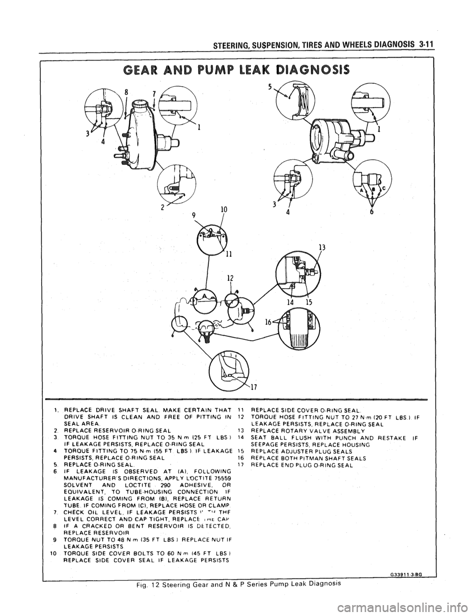
1. REPLACE DRIVE SHAFT SEAL MAKE CERTAIN THAT
DRIVE SHAFT IS CLEAN AND FREE OF PITTING IN
SEAL AREA
2 REPLACE RESERVOIR
0 RING SEAL 3 TORQUE HOSE FITTING NUT TO 35 N rn 125 FT LBS ) IF LEAKAGE PERSISTS, REPLACE O.RING SEAL 4 TORQUE FITTING TO 75 N rn 155 FT LBS 1 IF LEAKAGE
PERSISTS. REPLACE 0 RING SEAL 5 REPLACE O-RING SEAL 6 IF LEAKAGE IS OBSERVED AT (A). FOLLOWING
MANUFACTURER S DIRECTIONS. APPLY LOCTITE 75559
SOLVENT AND LOCTITE 290 ADHESIVE, OR
EQUIVALENT. TO TUBE HOUSING CONNECTION IF
LEAKAGE IS COMING FROM
101, REPLACE RETURN
TUBE IF COMING FROM IC), REPLACE HOSE OR CLAMP 7 CHECK OIL LEVEL, IF LEAKAGE PERSISTS i' ''4 THF
LEVEL CORRECT AND CAP TIGHT. REPLACE I nt CAP B IF A CRACKED OR BENT RESERVOIR IS DETECTED
REPLACE RESERVOIR
9 TORQUE NUT TO 48 N rn 135 FT LBS 1 REPLACE NUT IF
LEAKAGE PERSISTS
10 TORQUE SlDE COVER BOLTS TO 60 N m 145 FT LBS
REPLACE SlDE COVER SEAL IF LEAKAGE PERSISTS
11 REPLACE SlDE COVER O.RING SEAL
12 TORQUE HOSE FITTING NUT TO 27 N rn 120 FT LBS ) IF
LEAKAGE PERSISTS, REPLACE O.RING SEAL
13 REPLACE ROTARY VALVE ASSEMBLY
14 SEAT BALL FLUSH WITH PUNCH AND RESTAKE IF
SEEPAGE PERSISTS. REPLACE HOUSING
15 REPLACE ADJUSTER PLUG SEALS 16 REPLACE BOTH PITMAN SHAFT SEALS
17 REPLACE END PLUG O.RING SEAL
Page 138 of 1825
STEERING, SUSPENSION, TIRES AND WHEELS DIAGNOSIS 3.13
in doubt about the condition, compare with a
shock known to be good.
Noisy
For struts, follow Steps 1 through 3.
1. Check all mountings for proper torque. A loose
mounting will cause a noise.
2. If all mountings are intact, bounce the car as in
Step
4 (weak) to isolate the suspected unit.
3. If practical, ride with the owner to be sure you
understand the complaint, before proceeding to
next step.
4. If one of the rear shocks is noisy, the rear axle
should be supported at least enough to unload the
shock mounts. Disconnect the lower mounting of
the suspected shock. Quickly push the shock all
the way in, then all the way out.
A hissing noise
is normal.
5. Other objectionable noises may be detected by
stroking. Any sound other
than hissing is
abnormal; replace the shock.
Leaks
1. Fully extend the strut/shocks (wheels
unsupported) to expose the seal cover area for
inspection.
2. Look for
signs of leaks in the seal cover area.
3. A slight trace of fluid is NOT cause for
replacement; the seal permits some seepage to
lubricate the piston rod. There is a built in fluid
reserve to allow for seepage.
4. A leaking strut dampener/shock can easily be
found because there will be fluid around the seal
cover and an excessive amount of fluid on the
strut
dampener/shock. A leaking strut
dampener/shock must be replaced.
BENCH CHECKS
Strut Dampeners and Regular Shock Absorbers
(Standard and Firm Ride)
Regular strut dampenerdrear shocks use a
gas-filled cell in the fluid reservoir. Aeration or
foaming of the fluid is eliminated, as the gas and the
fluid cannot mix.
Proceed with the actual bench check as follows:
1. Clamp the strut dampener/shock UPSIDE
DOWN in the vise. Do not clamp on the reservoir
tube or the mounting threads. If a lag is noticed
when it is stroked, it means the gas-filled cell has
ruptured and replacement is necessary.
2. Pump strut dampener/shock by hand at various
rates of speed and note the resistance.
3. Rebound resistance normally is stronger than
compression resistance by about 2 to 1. However,
the resistance should be smooth and constant for
each stroking rate.
4. Compare with a strut dampener/ shock known to
be good.
5. It is normal to hear a hissing noise. The following
symptoms are abnormal and are reason for
replacement. A.
A skip or lag at reversal near mid-stroke.
B. A seize (except at either extreme end of
travel).
C. A noise (such as a grunt or squeal) after
completing one full stroke in both
directions.
D. A clicking noise at fast reversal.
E. Fluid leakage.
TIRE DIAGNOSIS
Irregular and Premature Wear
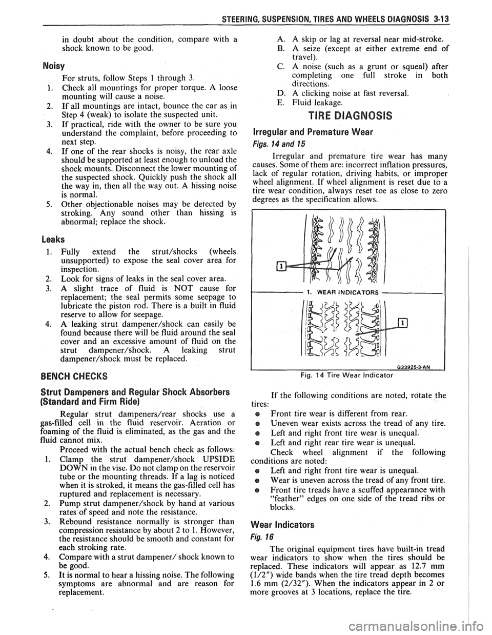
Figs. 14 and 15
Irregular and premature tire wear has many
causes. Some of them are: incorrect inflation pressures,
lack of regular rotation, driving habits, or improper
wheel alignment. If wheel alignment is reset due to a
tire wear condition, always reset toe as close to zero
degrees as the specification allows.
1. WEAR INDICATORS I
Fig. 14 Tire Wear Indicator
If the following conditions are noted, rotate the
tires:
@ Front tire wear is different from rear.
Uneven wear exists across the tread of any tire.
e Left and right front tire wear is unequal.
Left and right rear tire wear is unequal.
Check wheel alignment if the following
conditions are noted:
e Left and right front tire wear is unequal.
Wear is uneven across the tread of any front tire.
e Front tire treads have a scuffed appearance with
"feather" edges on one side of the tread ribs or
blocks.
Wear Indicators
Fig. 16
The original equipment tires have built-in tread
wear indicators to show when the tires should be
replaced. These indicators will appear as 12.7 mm
(1/2") wide bands when the tire tread depth becomes
1.6 mm (2/32"). When the indicators appear in 2 or
more grooves at
3 locations, replace the tire.
Page 148 of 1825
-
WHEEL. ALIGNMENT 3A-1
SECTION 3A
WHEEL AL GNMENT
NOTICE: These fasteners are important attaching Do not use a replacement part of lesser quality or
parts, in that they could affect the performance of substitute
design. Torque values must be used as
vital components and systems, and/or could result specified during reassembly to assure proper
in major repair expense. They must be replaced retention of these parts. For prevailing torque
with one of the same part number or with an
nut(s) and bolt(s), refer to the "Reuse of Prevailing
equivalent part if replacement becomes necessary. torque
Nut(s) and Bolt(s)" chart in Section 0.
General Description ...................... .. ...... 3A- 1 On-Car Service ........................ .. ........... 3A-2
Caster .................... .. ............................ 3A- 1 Caster and Camber Adjustment .................. 3A-2
..................................... Camber ................... .. .............................. 3A-I Toe-In Adjustment 3A-2
Toe.. ................................................. 3A- 1 Axle Housing Alignment ......................... .... 3A-4
Preliminary Checks Prior to Specifications ....................... ... ............... 3A-4
Adjusting Alignment ..................... ...... 3A- 1
GENERAL DESCRIPmIOMI
Wheel alignment refers to the angular they tend to roll parallel on the road when the car is
relationship between the wheels, the suspension moving.
attaching parts and the ground.
PRELIMINARY CHECKS PRIOR TO ADJUSTING
CASTER ALIGNMENT
Figure 1
Caster is the amount the top of the strut is tilted
forward or rearward from the vertical. When the strut
tilts rearward, the center is "positive"
(+). The
amount of tilt is measured in degrees from vertical.
CAMBER
Figure 1
Camber is the tilting of the wheels from the
vertical when viewed from the front of the car. When
the wheels tilt outward at the top, the camber is said
to be positive
(+). When the wheels tilt inward at the
top, the camber is said to be negative
(-). The amount
of tilt is measured in degrees from the vertical and this
measurement is called the camber angle.
TOE
Figure i
Toe is a measurement of how much the front of
the wheels are turned in or out from a straight-ahead
position. When the wheels are turned in, toe is
"positive"
(+). When the wheels are turned out, toe
is "negative"
(-). The actual amount of toe-in is
normally only a fraction of a degree. The purpose of a
toe specification is to ensure parallel rolling of the
wheels (excessive toe-in or toe-out may increase tire
wear). Toe also serves to offset the small deflections of
the wheel support system which occur when the car is
rolling forward. In other words, even when the wheels
are set to toe-in slightly when the car is standing still, Steering
and vibration complaints are not always
the result of improper alignment. Another possibility
is tire "lead" due to worn or improperly manufactured
tires. "Lead" is the deviation of the car from a straight
path on a level road without hand pressure on the
steering wheel. Section
3 of this manual contains a
procedure for determining the presence of a tire lead
problem.
Before making any adjustment affecting wheel
alignment, make the following checks to ensure correct
alignment readings and alignment adjustments:
1. Check all tires for proper inflation pressures and
approximately the same tread wear.
2. Hub and bearing assemblies for excessive wear;
correct if necessary.
3. Ball joints and tie rod ends; if they are excessively
lcose, correct them before adjusting.
4. Run-out of wheels and tires.
5. Car trim height; if out of limits and a correction
is to be made, do so before adjusting alignment.
Refer to Section
3 for trim height specifications.
6. Strut dampeners for proper operation.
7. Control arms for loose bushings.
8. Loose or missing stabilizer bar attachments.
Consideration must be given to excess loads, such
as tool boxes, sample cases, etc. If these items are
normally carried in the car, they should remain in the
car during alignment adjustments. Consideration
should also be given to the condition of the equipment
used to adjust alignment. Be sure to follow the
equipment manufacturer's instructions. Regardless
of