1988 PONTIAC FIERO service
[x] Cancel search: servicePage 58 of 1825
AIR GONDlTlONlNG 1B-15
involves opening the refrigeration system. Always
work in a well ventilated area and avoid breathing any
refrigerant fumes. If liquid refrigerant comes into con-
tact with the eyes, injury may result.
@ Before removing and replacing any of the air
conditioning refrigeration lines or components,
the system must be completely discharged of
Refrigerant- 12.
@ Always use service valve and pressure gauge
sets during evacuation and charging procedures.
@ Always discharge system at low-side service fit-
ting and perform the entire evacuate and charg-
ing procedure through the low-side service
fitting.
@ Do not connect high-pressure line or any line to
the high-side
service fitting during discharging
and charging procedures.
CAUTION: Never remove a gauge line
from its adapter when line is connected
to
AIC system. Always remove the line
adapter from the service
fining to dis-
connect a line. Do not remove charging
hose at gauge set while
anached to ser-
vice low-side
fining. This will result in
complete discharge of system due to
the depressed Schrader valve in
service
low-side fining and may cause personal
injury due to escaping Refrigerant-12.
Discharging the NG System
In replacing any of the air conditioning refriger-
ation components, the system must be completely dis-
charged of Refrigerant- 12.
ALWAYS DISCHARGE SYSTEM AT
LOW-SIDE SERVICE FITTING.
1. With ignition turned "OFF," remove protective
cap from LOW-SIDE service fitting (on most
models) on Accumulator and connect charging
station
J-23500-01 or equivalent gauge set. If
charging station J-23500-01 or equivalent is not
being used, discharge system by slowly con-
necting a gauge hose to low-side
sewice fitting
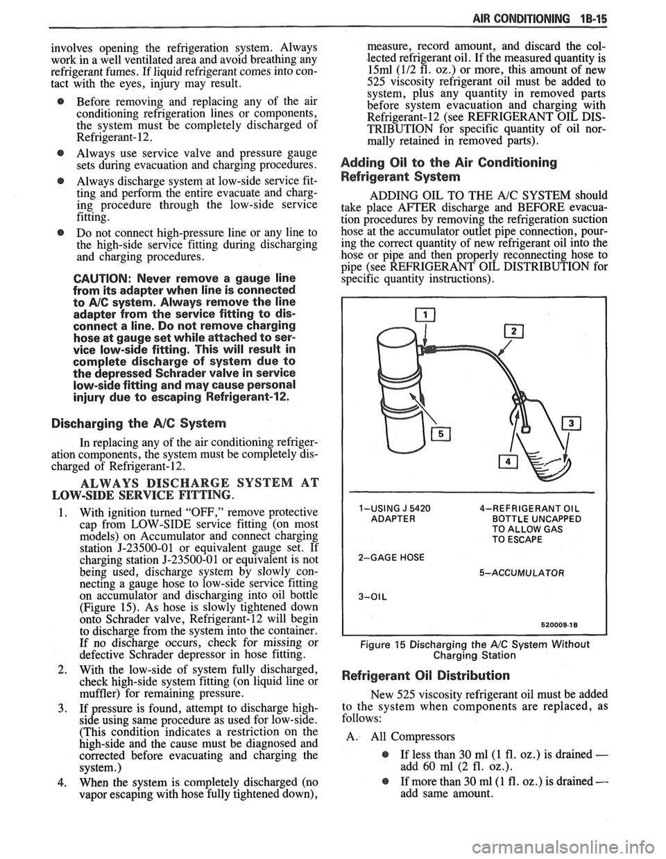
on accumulator and discharging into oil bottle
(Figure 15). As hose is slowly tightened down
onto Schrader valve, Refrigerant-12 will begin
to discharge from the system into the container.
If no discharge occurs, check for missing or
defective Schrader depressor in hose fitting.
2. With the low-side of system fully discharged,
check high-side system fitting (on liquid line or
muffler) for remaining pressure.
3. If pressure is found, attempt to discharge high-
side using same procedure as used for low-side.
(This condition indicates a restriction on the
high-side and the cause must be diagnosed and
corrected before evacuating and charging the
system.)
4. When the system is completely discharged (no
vapor escaping with hose fully tightened down), measure, record
amount, and discard the col-
lected refrigerant oil. If the measured quantity is
15ml (112 fl. 02.) or more, this amount of new
525 viscosity refrigerant oil must be added to system, plus any quantity in removed parts
before system evacuation and charging with
Refrigerant-12 (see REFRIGERANT OIL DIS-
TRIBUTION for specific quantity of oil nor-
mally retained in removed parts).
Adding Oil to the Air Conditioning
Refrigerant System
ADDING OIL TO THE A/C SYSTEM should
take place AFTER discharge and BEFORE evacua-
tion procedures by removing the refrigeration suction
hose at the accumulator outlet pipe connection, pour-
ing the correct quantity of new refrigerant oil into the
hose or pipe and then properly reconnecting hose to
pipe (see REFRIGERANT OIL DISTRIBUTION for
specific quantity instructions).
1-USING J 5420 4-REFRIGERANT OIL BOTTLE UNCAPPED
TO ALLOW GAS
TO ESCAPE
2-GAGE HOSE 5-ACCUMULATOR
Figure 15 Discharging the A/C System Without
Charging Station
Refrigerant Oil Distribution
New 525 viscosity refrigerant oil must be added
to the system when components are replaced, as
follows:
A. All Compressors
@ If less than 30 ml(1 fl. oz.) is drained -
add 60 ml (2 fl. oz.).
@ If more than 30 ml(1 fl. oz.) is drained --
add same amount.
Page 59 of 1825
"18-16 AIR CONDITIONING
B . Accumulator dehydrator
@ Add 105 ml (3.5 fl. 02.) to new
accumulator
C. Evaporator
@ Add 90 ml (3 fl. oz.) oil
D. Condenser
@ Add 30 ml (1 fl. 02.) oil
Refrigerant oil loss due to a large leak
If the refrigerant charge is aburptly lost due to a
large refrigerant leak, approximately 90
ml (3 fl. oz.)
of refrigerant oil will be
carried out of the system sus-
pended in the refrigerant. Any failure that caused an
abrupt refrigerant discharge will experience this oil
loss. Failures that allow the refrigerant to seep or
bleed off over time do not experience this oil loss.
Upon replacement of a component which
caused a large refrigerant leak, add 90 ml(3
fl. oz.) of
new 525 viscosity refrigerant oil plus the required
amount of oil for the particular component (as out-
lined above).
Add the oil directly to the replaced component if
possible. If the oil cannot easily be added to the
replaced part, add the oil to the accumulator.
Evacuating and Charging the A/C System
If the system has been opened for any repair, or
the Refrigerant-12 charge lost, the system must be
evacuated prior to charging.
Evacuating and charging is a combined proce-
dure, and all gauge lines must be purged with R-12
prior to charging.
There are three evacuate and charge procedures.
1.
J 23500-01 Charging Station Method
2. Disposable Can Method 3. Drum Method
NOTICE: Under no circumstances should alco-
hol be used in the system in an attempt to remove
moisture. Damage to the system components
could occur.
Gauge Calibration
Prior to evacuation, check the low-pressure
gauge for proper calibration and determine if vacuum
system is operating properly.
With the gauge disconnected from the refrigera-
tion system, be sure that the pointer indicates to the
center of
"0". Lightly tap gauge a few times to be sure
pointer is not sticking. If necessary, calibrate as
follows:
1. Remove cover from gauge.
2. Holding gauge pointer adjusting screw firmly
with one hand, carefully force pointer in the
proper direction to position pointer at the
"0"
position. Tap gauge a few times to be sure
pointer is not sticking. Replace gauge cover.
Vacuum System Check
Before connecting vacuum pump to the A/C
system, run pump connected to the low-pressure
gauge to determine the vacuum pump capability. If
the vacuum system is unable to reach
7 1 1.2-736.6mm
(28"-29") or more vacuum, the system should be
checked for leaks. If no leaks are found, the vacuum
pump may require repair.
5-23580-81 OR EQUIVALENT CHARGING
STATION METHOD.
Follow charging instructions provided with the
5-23500-01 Charging Station or equivalent in use with
the following exceptions:
1. Do
not connect the high-pressure line to the air
conditioning system.
2. Keep the high-pressure valve on the charging
station closed at all times.
3.
Perform the entire evacuate and charge proce-
dure through the accumulator low-side pressure service fitting.
4. Following these procedures will prevent acci-
dental high-side vehicle system pressure being
subjected to the charging station in the event an
error is made in valve sequence during compres-
sor operation to pull in the Refrigerant-12
charge.
DISPOSABLE CAN OR REFRIGERANT
DRUM METHOD.
If the Refrigerant-12 drum is used, place it on a
scale and note the total weight before charging. Watch
the scale during charging to determine the amount of
R-12 used.
If disposable
420ml (14 ounce) R-12 cans are
used, close the tapping valve and then attach
can(s)
following instructions included with the tapping valve
or tapping manifold adapter.
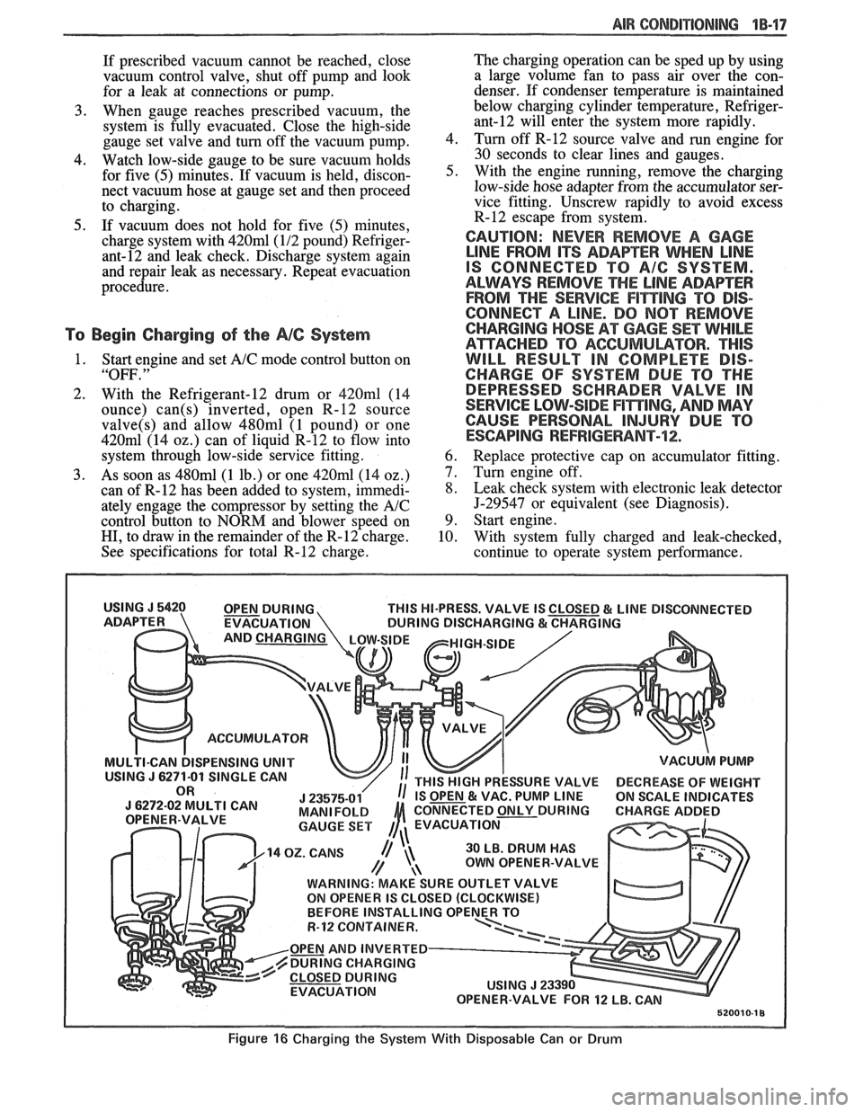
1. Connect manifold gauge set 5-23575-01 as fol-
lows. Also see Figure 16.
a. Eow-pressure gauge to accumulator fit-
ting.
b. Gauge set center hosk to Refrigerant-12
source.
c. High-pressure gauge to vacuum pump.
2. To begin evacuation of the
A/C system with
manifold gauge set and vacuum pump as illus-
trated in Figure 16, slowly open
high- and low-
side gauge valves and begin vacuum pump oper-
ation. Pump the system until the low-side gauge
reaches 7 1
1.2-736.6mm (28"-29") vacuum.
Note that in all evacuation procedures, the spec-
ification of 7 1
1.2-736.6mm (28"-29") vacuum is
used. This specification can only be reached at
or near sea level. For each
304.8m (1,000 feet)
above sea level, specification should be lowered
by one inch vacuum. At
1524m (5,000 feet)
elevation, only
584.2-609.6mm (23"-24") of
vacuum is required.
Page 60 of 1825
AIR CONDITIONING 1B-17
If prescribed vacuum cannot be reached, close
vacuum control valve, shut off pump and look
for a leak at connections or pump.
3. When gauge reaches prescribed vacuum, the
system is fully evacuated. Close the high-side
gauge set valve and turn off the vacuum pump.
4. Watch low-side gauge to be sure vacuum holds
for five (5) minutes. If vacuum is held, discon-
nect vacuum hose at gauge set and then proceed
to charging.
5. If vacuum does not hold for five (5) minutes,
charge system with
420ml(1/2 pound) Refriger-
ant-12 and leak check. Discharge system again
and repair leak as necessary. Repeat evacuation
procedure.
To Begin Charging of the NC System
1. Start engine and set A/C mode control button on
"OFF. "
2. With the Refrigerant-12 drum or 420ml (14
ounce)
can(s) inverted, open R-12 source
valve(s) and allow 480ml (1 pound) or one
420m1 (14 02.) can of liquid R-12 to flow into
system through low-side service fitting.
3. As soon as 480ml (1 lb.) or one 420ml (14 oz.)
can of R-12 has been added to system, immedi-
ately engage the compressor by setting the
A/C
control button to NORM and blower speed on
HI, to draw in the remainder of the R-12 charge.
See specifications for total R-12 charge. The
charging operation can be sped up by using
a large volume fan to pass air over the con-
denser. If condenser temperature is maintained
below charging cylinder temperature,
Refriger-
ant-12 will enter the system more rapidly.
4. Turn off
R-12 source valve and run engine for
30 seconds to clear lines and gauges.
5. With the engine running, remove the charging
low-side hose adapter from the accumulator ser-
vice fitting. Unscrew rapidly to avoid excess
R-12 escape from system.
CAUTION: NEVER REMOVE A GAGE
LINE FROM ITS ADAPEER WHEN LINE
IS CONNECTED TO A/G SYSTEM.
ALWAYS REMOVE
THE LINE ADAPTER
FROM THE
SERVICE F1miNG TO DIS-
CONNECT A LINE. DO
NOT REMOVE
CHARGING
HOSE AT GAGE SET WHILE
ATTACHED TO ACGUMULBTOR. "THIS
WILL RESULT IN COMPLETE DIS-
CHARGE OF SYSTEM DUE TO THE
DEPRESSED SCHRADER VALVE IN
SERVICE LOW-SIDE
F17$TING, AND MAY
CAUSE PERSONAL
INJURY DUE TO
ESCAPING REFRIGERANT-72;.
6. Replace protective cap on accumulator fitting.
7. Turn engine off.
8. Leak check system with electronic leak detector
5-29547 or equivalent (see Diagnosis).
9. Start engine.
10. With system fully charged and leak-checked,
continue to operate system performance.
THIS HI-PRESS. VALVE IS
EVACUATION
ACCUMULATOR
ISPENSING UNIT
30 LB. DRUM HAS
OWN OPENER-VALVE
WARNING: MAKE SURE OUTLET VALVE
ON OPENER IS CLOSED (CLOCKWISE)
R-12 CQNTAINER.
OPEN AND INVERTED
DURING CHARGING
EVACUATION
Figure 16 Charging the System With Disposable Can or Drum
Page 62 of 1825
AIR CONDITIONING 18-19
3. Push the tube into the fitting, bottoming it out.
Tighten
@ Torque nut to 15 Nam (11 lbs. ft.).
4. Dissasemble the joint.
5. Lubricate the
"0" ring with clean 525 viscosity
refrigerant oil.
6. Install the
"0" ring
on the tube. (See figure 17b)
7. Reassemble joint.
Tighten
@ Torque nut to 15 Nem (11 lbs. ft.).
8. Evacuate, charge, and leak test the system.
EXPANSlON "%BE (ORIFICE) SERVlCE
Remove or Disconnect
1. Discharge system.
2. Loosen fitting
at liquid line to evaporator inlet
pipe and remove tube carefully with needle
nosed pliers or Tool
5-26549-C or equivalent.
Install or Connect
1. Install
new orifice tube with shorter screen end
in first.
2. Install
liquid line and torque to proper
specification.
3. Evacuate and charge system.
In the event that difficulty is encountered during
the removal of a restricted or plugged expansion tube
(orifice tube), the following procedure is recom-
mended:
1. Remove
as much of any impacted residue as
possible.
2. Carefully apply heat with heat gun (hair drier,
epoxy drier or equivalent) approximately
114
inch from dimples on inlet pipe. Do not over-
heat pipe.
NOTICE: If the system has a pressure switch
near the orifice tube location, it should be
removed prior to heating the pipe to avoid dam-
age to switch.
3. While applying heat, use orifice removal tool
5-26549-C to grip the orifice tube. Use a turning
motion along with a push-pull motion to loosen
to the impacted orifice tube and remove it.
4. Swab inside of evaporator inlet pipe with R-11.
5, Add
1 oz. of 525 viscosity refrigerant oil to
system.
6. Lubricate new orifice tube and O-ring with 525'
viscosity refrigerant oil and insert into inlet
pipe. Install in proper direction (smaller screen
first).
ACCUMULATOR ASSEMBLY SERVICE
The accumulator assembly for the refrigerant
system has a service replacement which includes two
(2) O-rings (for the inlet and outlet connections). The
desiccant within the shell is NOT serviced separately
- it is part of the sealed accumulator assembly. See
REFRIGERANT OIL DISTRIBUTION for condi-
tions when the accumulator must be removed from the
vehicle to measure the amount of oil present inside the
accumulator.
The accumulator assembly should ONLY be
replaced when:
1. A physical perforation to the accumulator is
found, resulting in a leak.
2. If the system is open to air for an extended
period of time (due to a front-end collision,
removed parts, ect.). The desiccant bag will be
saturated with moisture.
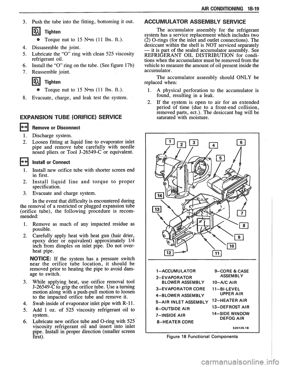
1 -ACCUMULATOR 9-CORE & CASE
2-EVAPORATOR BLOWER ASSEMBLY
10-A/C AIR
3-EVAPORATOR CORE 11-BI-LEVEL
4-BLOWER ASSEMBLY 5-AIR INLET ASSEMBLY
'IR
6-OUTSIDE AIR 13-DEFROST
AIR
7-INSIDE
AIR 14-SIDE WINDOW
DEFOG AIR
8-HEATER CORE
Figure 18 Functional Components
Page 63 of 1825
18-28 AIR CONDITIONING
DO NOT REPLACE the accumulator assembly
when:
1. Merely a dent is found in the outer shell of the
accumulator.
2. A
vehicle is involved in a collision and no phys-
ical perforation to the accumulator is found.
OM-VEHICLE SERVICE
R-"1 CHARGING CAPACITIES
The 420ml (14 fl. oz.) disposable can of R-12
refrigerant is equivalent to .399 kg (. 88 lb.).
BLOWER MOTOR
a Remove or Disconnect
1. Disconnect negative battery cable.
2. Remove motor cooling tube.
3. Disconnect electrical connections.
4. Remove blower motor attaching screws, remove
motor and case assembly.
5. Loosen retaining nut and remove blower cage
from motor shaft.
6. Inspect blower cage for broken vanes, etc.
Replace if necessary.
Install or Connect
1. Reverse removal procedure to reinstall. Replace
seals or sealant as required.
HI-BLOWER RELAY
Relay is a plug-in type with connector mounted
on top of the evaporator case.
BLOWER RESISTOR
Remove or Disconnect
1. Disconnect negative battery cable.
2. Disconnect electrical connections.
3. Remove two (2) screws, remove resistor.
Install or Connect
1. Reverse removal procedure to reinstall.
CONTROLLER, BLOWER SWITCH OR
WCUUM VALVE
Remove or Disconnect
1. Disconnect negative battery cable.
2. Remove NC control-radio console trim plate.
3. Remove three (3) NC control retaining screws.
4. Pull A/C control out and disconnect electrical
and vacuum connections and remove tempera-
ture cable.
5. Remove A/C control and replace vacuum valve
or blower switch as required.
Install or Connect
1. Reverse removal procedure to reinstall. Install
lower right screw in controller first to align con-
troller in console.
TEMPERATURE CONTROL CABLE,
VACUUM HARNESS
Remove or Disconnect
1. Remove the following hush panel(s):
a. Vacuum Harness - R.H. and L.H. hush
panel.
b. Temperature Cable
- R.H. hush panels.
Remove
controller/radio console trim plate.
Remove three (3) controller screws and pull
controller partially out of console.
Disconnect controller
end(s) of temperature
cable
andlor vacuum harness.
Disconnect component
end(s) of temperature
cable
andlor vacuum harness.
Install or Conned
1. Reverse removal procedure to reinstall. When
installing controller, install lower right screw
first to align controller location. Replace any
retaining straps, etc. removed.
2. Perform functional check of controller.
CONTROL WlRlNG HARNESS
a Remove or Disconnect
1. Disconnect negative battery cable.
2. Remove
control/radio console trim plate and
hush panels (see Section
8C).
3. Remove three (3) screws holding control in con-
sole and pull control out far enough to discon-
nect electrical and vacuum connector. Remove
controller.
4. Remove instrument panel carrier (see Section
8C).
5. Remove heater case covers (core and mode door
sides).
6. Remove two (2) interior screws and one (1)
exterior nut holding case to cowl. Pull left side
of case back to gain access to harness at cowl.
Case will still be retained by one (I) screw
behind the evaporator core
- do not attempt
complete removal of case. -
7. Loosen cowl grommet and disconnect purple
vacuum line.
Page 80 of 1825
W-4 AIR CONDITIONING COMPRESSOR OVERHAUL 1 Dl-l
SECTION 1 Dl
R COND NG COMPRESSOR
OVERHAUL
For Compressor REMOVAL AND INSTALLATION, see Air Conditioning Section 1B. For
DISCHARGING, ADDING OIL, EVACUATING AND CHARGING PROCEDURES FOR
A/C
SYSTEMS, see Air Conditioning Section 1B.
CONTENTS
General Description ............................... 1D1-1
Service Procedures .................................. 1D1-4
Minor Repair Procedures ....................... 1D1-4
Clutch Plate and Hub Assembly ............... 1D1-4
Clutch Rotor and Bearing: Four-Pole
Clutch
..................................................... 1D1-5
Clutch Rotor and Bearing: Six-Pole
Clutch
.......................... ... ....................... 1 D 1-7
Clutch Coil and Pulley Rim ...................... 1 D 1 - 10
Major Repair Procedures ....................... 1D1-12
Shaft Seal .................................................. 1Dl-12
Seal Leak Detection ........................... .... 1D1-12
Replacement (On Car) ........................... 1 D 1- 12
Replacement (Off Car)
........................... 1 D 1 - 13
Pressure Relief Valve
................................. 1 D 1 - 13
Nigh Pressure Cut-Off Switch
................... 1 D 1 - 13
Front Head and 0-Ring
............................ 1 D 1 - 14
Thrust and Belleville Washers
................... 1 D 1 - 16
Main Bearing
.............................................. 1 D 1- 16
Shell and 0-Ring
....................................... 1D 1- 17
Discharge Valve Plate and Retainer
......... 1 D 1 - 18
Cylinder and Shaft Assembly
.................... 1 D 1 - 19
Leak Testing (External and Internal)
........ 1D1- 19
Special Tools ..................................... ... .. 1D1-21
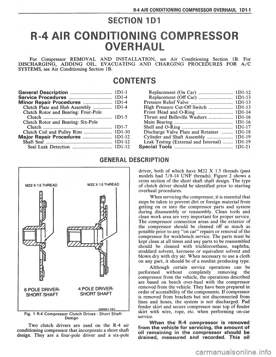
GENERAL DESCRIPTION
M22 X 1.5 THREAD M22 X 1.5 THREAD
6 POLE DRIVER- 4 POLE DRIVER-
SHORT SHAFT SHORT SHAFT
J20001.1 Dl
Fig. 1 R-4 Compressor Clutch Drives - Short Shaft
Desian
driver, both of which have M22 X 1.5 threads (past
models had 7/8-14
UNF threads). Figure 2 shows a
cross section of the short shaft shaft design. The type
of clutch driver should be identified prior to starting
overhaul procedures.
When servicing the compressor, it is essential that
steps be taken to prevent dirt or foreign material from
getting on or into the compressor parts and system
during disassembly or reassembly. Clean tools and
clean work area are very important for proper service.
The compressor connection areas and the exterior of
the compressor should be cleaned off as much as
possible prior to any "on car" repairs or removal of the
compressor for workbench service. The parts must be
kept clean at all times and any parts to be reassembled
should be cleaned with trichloroethane, naphtha,
stoddard solvent, kerosene or equivalent solvent and
blown dry with dry air. When necessary to use a cloth
on any part, it should be of a nonlint producing type.
Although certain service operations can be
performed without completely removing the
compressor from the vehicle, the operations described
are based on bench over-haul with the compressor
removed from the vehicle. They have been prepared in
order of accessibility of the components. If compressor
is removed from brackets but not disconnected from
lines and hoses, the system is not discharged. Pad
fender skirt and secure compressor near top of fender
skirt with wire, rope,
etc, when performing on-car
service.
., When the R-4 compressor is removed Two 'lutch drivers are wed On the R-4 air from the vehicle for servicing, the amount of conditioning compressor that incorporate a short shaft oil remaining in the should be design. They are a four-pole driver and a six-pole drained, measured and recorded. This oil
Page 83 of 1825
181-4 R-4 ABR CONDITIONING COMPRESSOR OVERHAUL
SERVICE PROCEDURES
MINOR REPAIR PROCEDURES
THE FOLLOWING OPERATIONS TO THE
R-4 COMPRESSOR CLUTCH PLATE AND 1 -SUCTION
HUB, ROTOR AND BEARING, AND COIL &
PULLEY RIM ARE COVERED AS 'WINOR" 3-DISCHARGE
BECAUSE THEY MAY BE PERFORMED
WITHOUT FIRST DISCHARGING THE
SYSTEM OR REMOVING THE
COMPRESSOR FROM THE VEHICLE. 5-~-25008-~
The two types of drive systems used on the R-4
Compressor (\I-groove type and poly-groove type)
affect only minor repair procedures and are so noted
where required. Major repair procedures are not
Fig. 6 Compressor In Holding Fixture affected by the type of drive system.
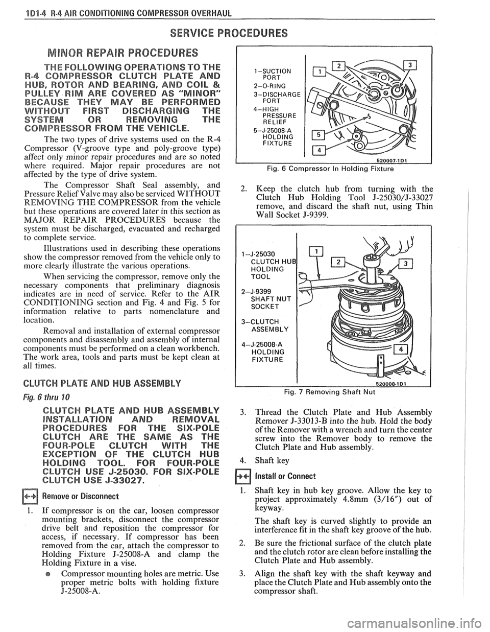
The Shaft and 2. Keep the clutch hub from turning with the
Pressure Relief Valve may also be serviced WITHOUT
REMOVING THE COMPRESSOR from the vehicle Clutch
Hub Holding Tool 5-25030/J-33027
remove, and discard the shaft nut, using Thin
but these operations are covered later in this section as
MAJOR REPAIR PROCEDURES because the Wall Socket
5-9399.
system must be discharged, evacuated and recharged
to complete service.
Illustrations used in describing these operations
show the compressor removed from the vehicle only to
more clearly illustrate the various operations.
CLUTCH HUB
When servicing the compressor, remove only the
necessary components that preliminary diagnosis
indicates are in need of service. Refer to the AIR
CONDITIONING section and Fig.
4 and Fig. 5 for
information relative to parts nomenclature and
location.
Removal and installation of external compressor
components and disassembly and assembly of internal
components must be performed on a clean workbench.
The work area, tools and parts must be kept clean at
all times.
CLUTCH PLATE AND HUB ASSEMBLY Fig. 7 Removing Shaft Nut Fig. 6 thru 10
CLUTCH PLATE AND HUB ASSEMBLY 3. Thread the Clutch Plate and Hub Assembly INSTALLATION AND REMOVAL Remover 5-33013-I3 into the hub. Hold the body
PROCEDURES FOR THE SIX-POLE of the Remover with a wrench and turn the center
CLUTCH ARE THE SAME AS THE screw into the Remover body to remove the
FOUR-POLE CLUTCH WITH THE Clutch Plate and Hub assembly.
EXCEPTION OF THE CLUTCH HUB
HOLDING TOOL. FOR FOUR-POLE 4. Shaft key
CLUTCH USE J-25030. FOR SIX-POLE
CLUTCH USE J-33027. Install or Connect
a Remove or Disconnect 1. Shaft key in hub key groove. Allow the key to
project approximately
4.8mm (3/16") out of
1. If compressor is on the car, loosen compressor keyway.
mounting brackets, disconnect the compressor
The shaft key is curved slightly to provide an
drive belt and reposition the compressor for
interference fit in the shaft key groove of the hub.
access, if necessary. If compressor has been
removed from the car, attach the compressor to 2. Be Sure the frictional surface of the clutch plate
Holding Fixture
J-'25008-8 and clamp the and
the clutch rotor are clean before installing the
Holding Fixture
in a vise. Clutch
Plate and Hub assembly.
Compressor mounting holes are metric. Use 3.
Align the shaft key with the shaft keyway and
proper metric bolts with holding fixture place the Clutch Plate and Hub assembly onto the
J-25008-A. compressor shaft.
Page 91 of 1825
4 Dl-I 2 R-4 AIR CONDITIONING COMPRESSOR OVERHAUL
MAJOR REPAIR PROCEDURES
Service repair procedures to the
Compressor Shaft Seal,
Pressure Relief Valve
or disassembly
of the Internal Compressor
Cylinder and Shaft Assembly are considered
"MAJOR" SINCE THE REFRIGERATION
SYSTEM MUST BE DISCHARGED,
EVACUATED AND RECHARGED to complete
service and/or because major internal
operating and sealing components of the
compressor are being disassembled and
serviced.
When replacing the shaft seal assembly or
pressure relief valve, even if the compressor remains on
the vehicle during the operation, it will be necessary to
discharge the system of refrigerant (see Section
1B).
Other than clutch repair procedures, the same holds
true for any disassembly of the compressor.
If the compressor shell, front head or cylinder
and shaft assembly are to be serviced or replaced, the
oil in the compressor must be drained, measured and
replaced (see Section
1B) to determine addition of
proper oil quantity to new assembly.
A clean workbench, preferably covered with a
sheet of clean paper, orderliness in the work area and
a place for all parts being removed and replaced is of
great importance, as is the use of the proper, clean
service tools.
NOTICE: Any attempt to use make-shift or
inadequate equipment may result in damage
and/or improper compressor operation.
All parts required for servicing the internal
compressor are protected by a preservation process and
packaged in a manner which will eliminate the
necessity of cleaning, washing or flushing of the parts.
The parts can be used in the internal assembly just as
they are removed from the service package.
Seals and
protective packaging should be left in tact un
ti1 just
prior to installation.
SI-IAFT SEAL
Fig. 35 thru 40
Shaft Seal Design
The shaft seal is a one piece design.
Seal Leak Detection
A shaft seal should not be changed because of an
oil-line on the hood insulator. The Seal is designed to
seep some oil for lubrication purposes. Only change a
Shaft Seal when a leak is detected by evidence of oil
sprayed in large amounts and then only after actual
refrigerant leakage is found by using an approved leak
Detector such as J-29547 or equivalent.
Should an R-4 compressor shaft seal ever have to
be replaced, the accumulator in this R-4 system must
also be removed from the vehicle. The oil in the
accumulator then must be drained, measured and
replaced according to the directions in Section
1B to
determine oil loss.
On-Car
Remove
or Disconnect
1. Discharge A/C system
2. Loosen and reposition compressor in mounting
brackets
3. Clutch Plate and Hub assembly
4. Shaft seal seat retainer ring, using Snap Ring
Pliers J-5403-A
5. Thoroughly clean inside of compressor neck area
and O-ring groove surrounding the shaft, the
exposed portion of the seal seat and the shaft
itself. Any dirt or foreign material getting into
compressor may cause damage.
6. Remove Lip Seal:
e Fully engage the knurled tangs of Seal
Remover-Installer J-23 128-A into the
recessed portion of the Seal by turning the
handle clockwise. Remove the Seal from the
compressor with a rotary-pulling motion.
Discard the Seal. The handle must be
hand-tightened securely. Do not use a
wrench or pliers.
7. Discard the seal seat O-ring from the compressor
neck using 0-Ring Remover J-9553-01.
8. Recheck the shaft and inside of the compressor
neck and O-ring groove for dirt or foreign
material and be sure these areas are perfectly
clean before installing new parts.
Inspection
Seals should not be reused. Always use a new
specification service seal kit on rebuild. Care should be
taken to prevent damage to the lip of the one piece seal.
Make sure that the Seal Seat and Seal Lip are free of
lint and dirt that could damage the seal surface or
prevent sealing.
On-Car
Install
or Connect
1. Dip
the new seal O-ring in clean 525 viscosity
refrigerant oil and assemble onto 0-Ring
Installer J-33011.
2. Insert
the 0-Ring Installer
5-3301 1 completely
down into the compressor neck until the Installer
"bottoms." Lower the moveable slide of the
0-Ring Installer to release the 0-Ring into the
seal seat O-ring lower groove. (The compressor
neck top groove is for the shaft seal retainer ring.)
Rotate the Installer to seat the O-ring and remove
the Installer.
3. Prepare Lip Seal:
Assemble seal to Seal Installer J-23128-A,
by turning handle clockwise, and then push
Seal Protector J-34614, into seal lip. The
stamped steel case side of the lip seal must
be engaged with knurled tangs of installer so
that flared-out side of lip seal is facing and
installed towards the compressor.
4. Install Lip Seal: