1988 PONTIAC FIERO seat adjustment
[x] Cancel search: seat adjustmentPage 370 of 1825
2.8 LITER V-6 6A2-19
4. Measure the crankpin for out-of-round or taper
with a micrometer. If not within specifications,
replace or recondition the crankshaft. If within
specifications and a new bearing is to be installed,
measure the maximum diameter of the crankpin,
to determine new bearing size required.
5. If within specifications, measure new or used
bearing clearance with Plastigage or its
equivalent.
NOTICE: If a bearing is being fitted to an
out-of-round crankpin, be sure to fit to the
maximum diameter of the crankpin. If the bearing
is fitted to the minimum diameter and the
crankpin is out-of-round .025mm interference
between the bearing and
crankpin will result in a
rapid bearing failure.
a.
Place a piece of gaging plastic the full width
of the
crankpin as contacted by the bearing
(parallel to the crankshaft).
b. Install
the bearing in the connecting rod and
cap.
c. Install
the rod cap and evenly torque nuts
to specifications. Do not turn the crankshaft
with gaging plastic installed.
d. Remove
the rod cap and using the scale on
the gaging plastic envelope, measure the
gaging plastic width at the widest point.
6. If
the clearance exceeds specifications, select a
new, correct size, bearing and remeasure the
clearance.
If clearance cannot be brought to within
specifications, the
crankpin will have to be
ground undersize. If the
crankpin is already
at maximum undersize, replace crankshaft.
7. Coat the
bearing surface with oil, install the rod
cap and torque nuts to 50
N-m (37 lb. ft.).
8. When all connecting rod bearings have been
installed tap each rod lightly (parallel to the
crankpin) to make sure they have clearance.
9. Measure all connecting rod side clearances (see
specifications) between the rod cap and
crankshaft throw (Figure 6A2-23).
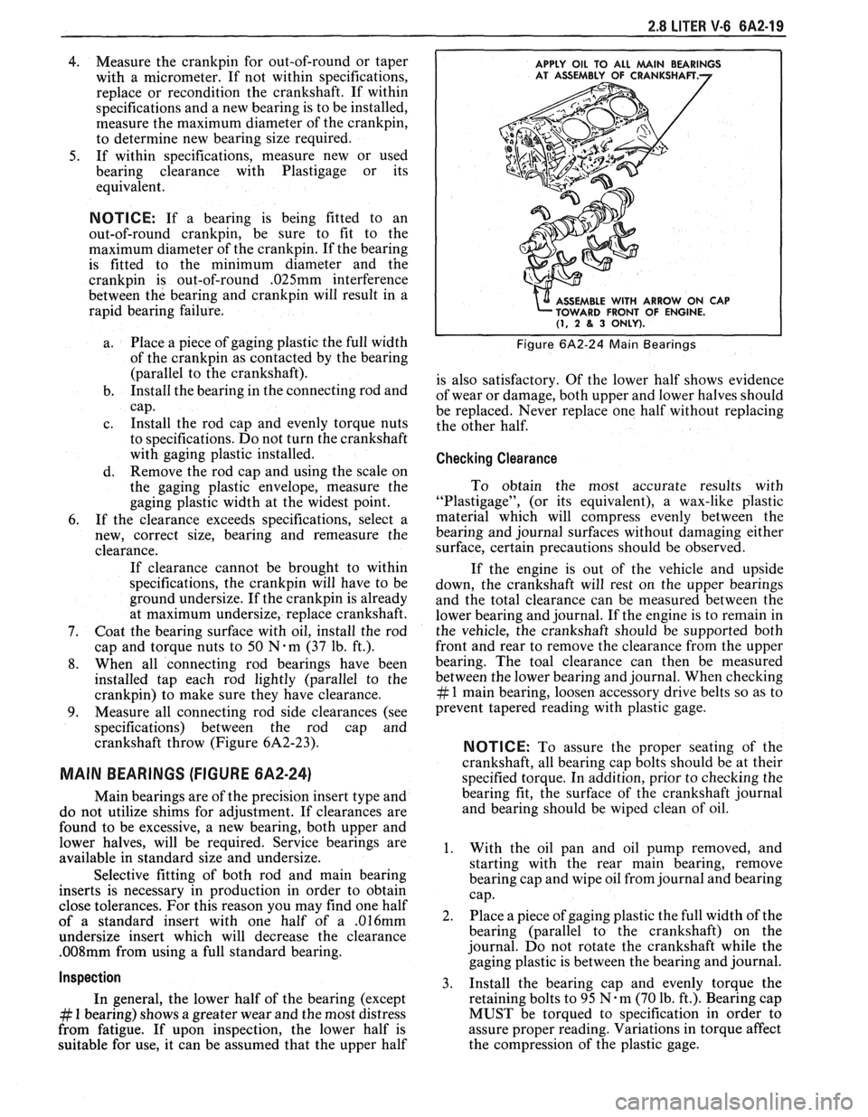
MAIN BEARINGS (FIGURE 6A2-24)
Main bearings are of the precision insert type and
do not utilize shims for adjustment. If clearances are
found to be excessive, a new bearing, both upper and
lower halves, will be required. Service bearings are
available in standard size and undersize.
Selective fitting of both rod and main bearing
inserts is necessary in production in order to obtain
close tolerances. For this reason you may find one half
of a standard insert with one half of a
.016mm
undersize insert which will decrease the clearance
.008mm from using a full standard bearing.
Inspection
In general, the lower half of the bearing (except
# 1 bearing) shows a greater wear and the most distress
from fatigue. If upon inspection, the lower half is
suitable for use, it can be assumed that the upper half
APPLY OIL TO ALL MAlN BEARINGS
E WITH ARROW ON CAP
FRONT OF ENGINE.
(1, 2 8, 3 ONLY).
Figure 6A2-24 Main Bearings
is also satisfactory. Of the lower half shows evidence
of wear or damage, both upper and lower halves should
be replaced. Never replace one half without replacing
the other half.
Checking Clearance
To obtain the most accurate results with
"Plastigage", (or its equivalent), a wax-like plastic
material which will compress evenly between the
bearing and journal surfaces without damaging either
surface, certain precautions should be observed.
If the engine is out of the vehicle and upside
down, the crankshaft will rest on the upper bearings
and the total clearance can be measured between the
lower bearing and journal. If the engine is to remain in
the vehicle, the crankshaft should be supported both
front and rear to remove the clearance from the upper
bearing. The toal clearance can then be measured
between the lower bearing and journal. When checking
# 1 main bearing, loosen accessory drive belts so as to
prevent tapered reading with plastic gage.
NOTICE: To assure the proper seating of the
crankshaft, all bearing cap bolts should be at their
specified torque. In addition, prior to checking the
bearing fit, the surface of the crankshaft journal
and bearing should be wiped clean of oil.
1. With the oil pan and oil pump removed, and
starting with the rear main bearing, remove
bearing cap and wipe oil from journal and bearing
cap.
2. Place a piece of gaging plastic the full width of the
bearing (parallel to the crankshaft) on the
journal. Do not rotate the crankshaft while the
gaging plastic is between the bearing and journal.
3. Install
the bearing cap and evenly torque the
retaining bolts to 95
N.m (70 lb. ft.). Bearing cap
MUST be torqued to specification in order to
assure proper reading. Variations in torque affect
the compression of the plastic gage.
Page 388 of 1825
V-8 ENGINE 6A3-9
surfaces of rocker arms and rocker arm balls
with "Molykote" or its equivalent.
1. Install push rods.
Be sure push rods seat in lifter
socket.
2. Install
rocker arms, rocker arm balls and rocker
arm nuts. Tighten rocker arm nuts until all lash
is eliminated.
3. Adjust
valves when lifter is on base circle of
camshaft lobe as follows:
a. Crank engine until mark on torsional
damper lines up with center or
"0" mark on
the timing tab fastened to the crankcase
front cover and the engine is in the
#l
firing position. This may be determined by
placing fingers on the
# 1 valve as the mark
on the damper comes near the
"0" mark on
the crankcase front cover. If the valves are
not moving, the engine is in the
# 1 firing
position. If the valves move as the mark
comes up to the timing tab, the engine is in
#6 firing position and should be turned
over one more time to reach the
#1
position.
b. With
the engine in the
# 1 firing position as
just determined, the following valves may be
adjusted:
e Exhaust--1, 3, 4, 8
e Intake--1, 2, 5, 7
, ,
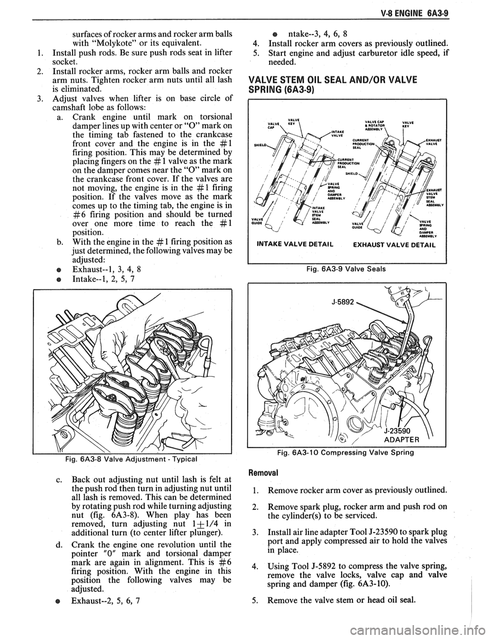
Fig. 6A3-8 Valve Adjustment - Typical
c. Back out adjusting nut until lash is felt at
the push rod then turn in adjusting nut until
all lash is removed. This can be determined
by rotating push rod while turning adjusting
nut (fig.
6A3-8). When play has been
removed, turn adjusting nut
1 + 1/4 in
additional turn (to center lifter plunger).
d. Crank
the engine one revolution until the
pointer
"0" mark and torsional damper
mark are again in alignment. This is
#6
firing position. With the engine in this
position the following valves may be
adjusted.
e Exhaust--2, 5, 6, 7
o ntake--3, 4, 6, 8
4. Install rocker arm covers as previously outlined.
5. Start engine and adjust carburetor idle speed, if
needed.
VALVE STEM OIL SEAL AND/OR VAL\/E
SPRING (6A3-9)
INTAKE VALVE DETAIL
EXHAUST VALVE DETAIL
Fig. 6A3-9 Valve Seals
Fig.
6A3-10 Compressing Valve Spring
Removal
1. Remove rocker arm cover as previously outlined.
2. Remove
spark plug, rocker arm and push rod on
the
cylinder(s) to be serviced.
3. Install air line adapter Tool J-23590 to spark plug
port and apply compressed air to hold the valves
in place.
4. Using Tool J-5892 to compress the valve spring,
remove the valve locks, valve cap and valve
spring and damper (fig.
6A3-10).
5. Remove
the valve stem or head oil seal.
Page 389 of 1825
QA3-10 V-8 ENGINE
lnstallation
1. Install valve stem seal over valve stem and seat
against head.
2. Set
the valve spring and damper, oil shedder and
valve cap in place. Compress the spring with Tool
J-5892 and install oil seal in the lower groove of
the stem, making sure the seal is flat and not
twisted. A light coat of oil on the seal will help
prevent twisting.
3. Install
the valve locks and release the compressor
tool making sure the locks seat properly in the
upper groove of the valve stem. Grease may be
used to hold the locks in place while releasing the
compressor tool.
4. Using tool J-23994, apply vacuum to the valve
cap to make sure no air leaks past the seal.
5. Install spark plug and torque to 22 lb. ft.
(30N.m).
6. Install and adjust valve mechanism as previously
outlined.
VALVE LIFTERS
Hydraulic valve lifters very seldom require
attention. The lifters are extremely simple in design,
readjustments are not necessary, and servicing of the
lifters requires only that care and cleanliness be
exercised in the handling of parts.
Valve Lifter Diagnosis
1.
Momentarily Noisy When Car is Started:
This condition is normal. Oil drains from the
lifters which are holding the valves open when the
engine is not running. It will take a few seconds
for the lifter to fill after the engine is started.
2. Intermittently Noisy On Idle Only. Disappearing
When Engine Speed is Increased:
Intermittent clicking may be an indication of a
pitted check valve ball, or it may be caused by
dirt.
Correction: Clean the lifter and inspect. If check
valve ball is defective, replace lifter.
3. Noisy At Slow Idle Or With Hot Oil, Quiet With
Cold Oil Or As Engine Speed Is Increased:
High leak down rate. Replace suspect lifter.
4. Noisy At High Car Speeds And Quiet At Low
Speeds:
a. High oil level
- Oil level above the "Full"
mark allows crankshaft counterweights to
churn the oil into foam. When foam is
pumped into the lifters, they will become
noisy since a solid column of oil is required
for proper operation. Correction: Drain oil
inti1 proper level is obtained.
b. Low oil level - Oil level below the "Add"
mark allows the pump to pump air at high
speeds which results in noisy lifters.
Correction: Fill until proper oil level is
obtained.
c. Oil pan bent on bottom or pump screen
cocked or loose, replace or repair as
necessary. 5.
Noisy At Idle Becoming Louder As Engine Speed
Is Increased To 1500 rpm:
This noise is not connected with lifter
malfunction. It becomes most noticeable in the
car at 10 to 15 mph "1" (Low) range, or 30 to
35
mph "DM (Drive) range and is best described as
a
hashy sound. At slow idle, it may be entirely
gone or appear as a light ticking noise in one or
more valves. It is caused by one or more of the
following:
a. Badly worn or scuffed valve tip and rocker
arm pad.
b. Excessive valve stem to guide clearance.
c. Excessive valve seat
runout.
d. Off square valve spring.
e. Excessive valve face
runout.
f. Valve spring damper clicking on rotator.
Removal
1.
Remove intake manifold as previously outlined.
2. Remove valve mechanism as previously outlined.
3. Remove valve lifter retainer.
4. Remvoe valve lifter restrictor.
5. Remove valve lifters (Fig.
6A3-7). Place valve
lifters in a rack so that they may be reinstalled in
the same location.
Installation
1.
Coat roller of valve lifters with "Molykote" or its
equivalent and install valve lifters.
2. Install valve lifter restrictor.
3. Install valve lifter retainer.
4. Install intake manifold as previously outlined.
5. Install and adjust valve mechanism as outlined.
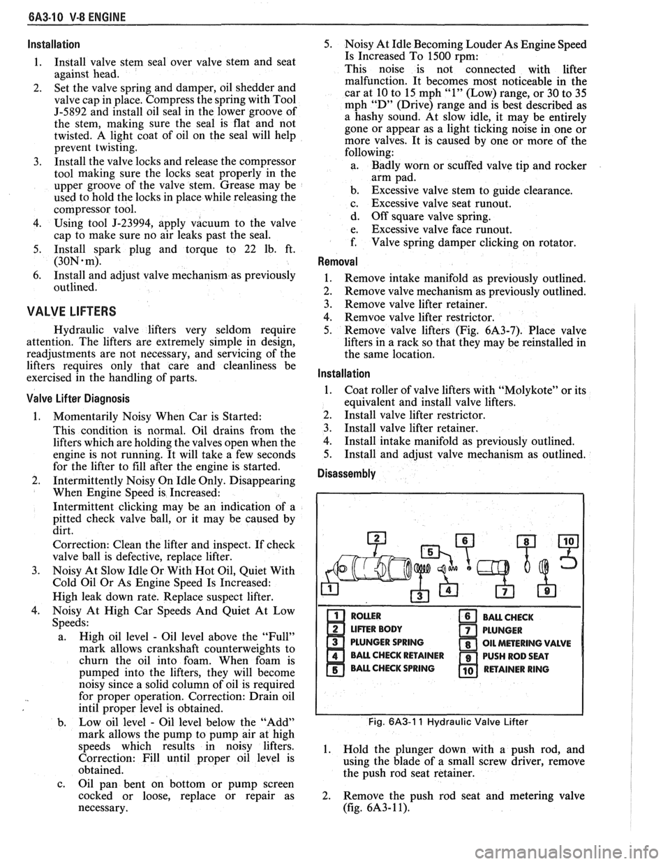
Disassembly
PLUNGER SPRING
Fig. 6A3-1 1 Hydraulic Valve Lifter
1. Hold the plunger down with a push rod, and
using the blade of a small screw driver, remove
the push rod seat retainer.
2. Remove the push rod seat and metering valve
(fig.
6A3- 1 1).
Page 437 of 1825
86-8 ENGINE FUEL
Fuel Tank Leak Test Procedure
Plug all outlets. Before removing a fuel tank for
a suspected fuel leak, make sure that it is not one of the
fuel hoses that is leaking onto the tank.
On-Car Test
If fuel is leaking from tank, replace tank.
Off-Car Pest
Apply a small amount of air pressure to tank
through vent tube (approximately
7 to 10 kPa or 1 to
1-1/2 lbs. of pressure).
NOTICE: More than 1-1/2 pounds of pressure
will damage tank permanently.
Test repaired area for leaks with soap solution, or
by submersion. If leak is noted, replace tank.
ACCELERATOR CONTROLS
The accelerator control system is cable type.
There are no linkage adjustments.
As there are no adjustments, the specific cable for
each application must be used. Only the specific
replacement part will work.
When work has been performed on accelerator
controls, always check to ensure that all components
are installed as removed and that all linkage and cables
are not rubbing or binding in any manner.
Accelerator Control Cable
Refer to On-Car Service for removal and
installation of accelerator control cable.
When performing service on the accelerator
control cable, observe the following:
s Retainer must be installed with tangs secured
over head of stud.
s Conduit fitting at both ends of cable must have
locking tangs expanded and locked in attaching
holes.
s The braided portion of the accelerator cable
assembly must not come in contact with the front
of dash sealer during assembly, repair or
replacement of the assembly.
e Flexible components (hoses, wires, conduits, etc.)
must be routed within
50.0mm (2.0 in.) of moving
parts of accelerator linkage, outboard of support,
unless routing is positively controlled.
Whenever disconnecting or replacing parts, lube
pivot points with Accelerator Linkage Lubricant
1052541, or equivalent.
Accelerator Pedal
When performing service on the accelerator
pedal, observe the following:
s The mounting surface between support and dash
panel must be free of insulation. The carpet and
padding in pedal and tunnel area must be
positioned to lay flat and be free of wrinkles and
bunches.
s Slip accelerator control cable through slot in rod
and then install retainer in rod, being sure it is seated.
Care must be utilized in pressing the
retainer into hole in rod, to assure the cable is not
kinked or damaged in any way.
s After securing all components of the accelerator
linkage, linkage must operate freely, without
binding, between full closed throttle and full wide
open throttle.
e Wire, hoses, cables or other obstructions must
not be placed within 13mm
(33/64 in.) of cable
or rod at any point in their travel.
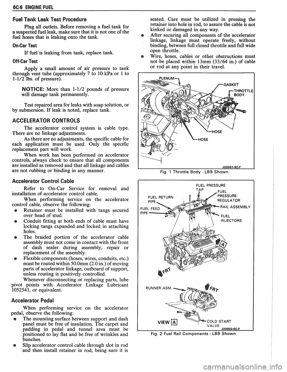
Fig. 1 Throttle Body - LB9 Shown
I FUEL PRESSURE I
FUEL RETURN
F
RAIL ASSEMBL
P
INJECTORS
VIEW COLD START
VALVE
J20002-6C-F
Fig. 2 Fuel Rail Components - LB9 Shown
Page 586 of 1825
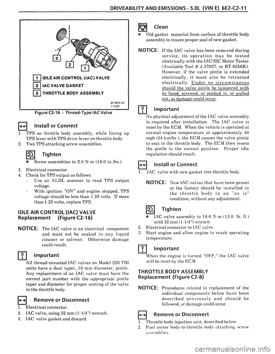
DRIVEABILITY AND EMISSIONS - 5.0L (VIN E) 6EZ-CZ-11
IDLE AIR CONTROL (IAC) VALVE
IAC VALVE GASKET
THROTTLE BODY ASSEMBLY
Figure C2-16 - Thread-Type IAC Valve
Install or Connect
1. TPS on throttle body assembly, while lining up
TPS lever with TPS drive lever on throttle body.
2. Two
TPS attaching screw assemblies.
Tighten
@ Screw assemblies to 2.0 N-m (18.0 in.lbs.).
3. Electrical connector.
4. Check for TPS output as follows: - Use an ALDL scanner to read TPS output
voltage.
- With ignition "ON" and engine stopped, TPS
voltage should be less than 1.25 volts. If more
than 1.25 volts, replace TPS.
IDLE AIR CONTROL (IAC) VALVE
Replacement (Figure CZ-16)
NOTICE:
The IAC valve is an electrical
component
and must not be soaked in any liquid
cleaner or solvent. Otherwise
damage
could result.
Important
All thread-mounted IAC valves on Model 220 TBI
units have a dual taper, 10 mm diameter, pintle.
Any replacement of an IAC valve must have the
correct part number with the appropriate pintle
taper and diameter for proper seating of the valve
in the throttle body.
Remove or Disconnect
1. Electrical connector.
2. IAC valve, using 32 mm (1-114") wrench.
3. IAC
valve gasket and discard.
Clean
@ Old gasket material from surface of throttle body
assembly to insure proper seal of new gasket.
NOTICE: If the IAC valve has been removed during
service, its operation may be tested
electrically with the
IACIISC Motor Tester
(Available Tool
# 5-37027, or BT-8256K).
However, if the valve pintle is extended
electrically, it must also be retracted
electrically. Under no circumstances
should the valve pintle be tampered with
by hand, screwed, or pushed in, or pulled
out, as damage could occur.
Important
No physical adjustment of the IAC valve assembly
is required after installation. The IAC valve is
reset by the ECM. When the vehicle is operated at
normal engine temperature at approximately 40
mph (64
kmlhr.), the ECM causes the valve pintle
to seat in the throttle body. The ECM then resets
the pintle to the correct position. Proper idle
regulation should result.
Install or Connect
1. IAC valve with new gasket into throttle body
NOTICE: New IAC valves that have been preset
at the factory should be installed in
the throttle
body in an "as is"
condition, without any adjustment.
Tighten
@ IAC valve assembly to 18.0 N.m (13.0 lb. ft.)
with 32 mm
(1-114") wrench.
2. Electrical connector to IAC valve.
3. Start engine and allow engine to reach operating
temperature.
Important
When the engine is turned "OFF," the IAC valve
will be reset by the ECM.
THROTTLE BODY ASSEMBLY
Replacement (Figure CZ-8)
NOTICE:
Procedures related to replacement of the
individual components below have been
described previously and should be
followed, or damage could occur.
Remove or Disconnect
1. Throttle body injection unit, described below
2. Fuel
meter body-to-throttle hodv attaching ~CI'PW
.i~~rmhlie
Page 587 of 1825
6E2-C2-12 DRIVEABILITY AND EMISSIONS - 5.0b (VIN E)
3. Fuel meter body assembly.
4. Throttle body-to-fuel meter body gasket. Discard
gasket.
a Disassemble
@ TPS from old throttle body, according to previous
instructions, for reuse on new throttle body. (New
IAC valve comes with new throttle body.)
Assemble
@ TPS onto replacement throttle body assembly,
according to previous instructions.
Install or Connect
1. New throttle body-to-fuel meter body gasket.
2. Fuel meter body assembly on throttle body
assembly.
3. Fuel meter body-throttle
body attaching screw
assemblies that have been coated with locking
compound.
Tighten
@ Attaching screw assemblies to 4.0 N.m
(35.0 Ib. in.).
4. TBI
unit onto engine, as described below.
MllMiMhlM IDLE SPEED CHECK
The idle stop screw, used in mechanically setting
minimum engine idle speed has been set at the factory
and should not require further adjustment. However,
to check that the setting is correct, proceed as follows:
I. Plug any vacuum ports, as required.
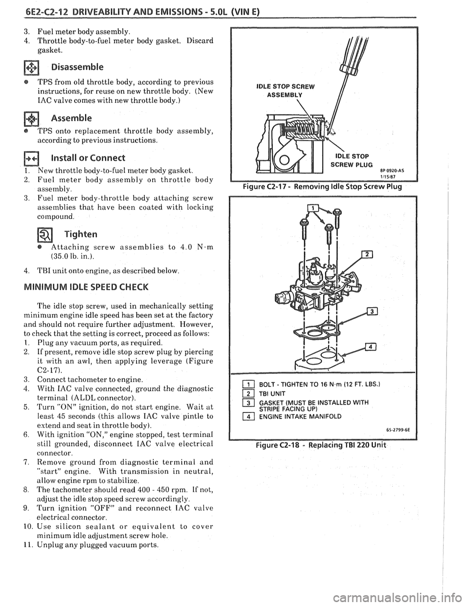
2. If present, remove idle stop screw plug by piercing
it with an awl, then applying leverage (Figure
C2-17).
3. Connect tachometer to engine.
4. With IAC valve connected, ground the diagnostic
terminal
(ALDL connector).
5.
Turn "ON" ignition, do not start engine. Wait at
least 45 seconds (this allows IAC valve pintle to
extend and seat in throttle body).
6. With ignition "ON," engine stopped, test terminal
still grounded, disconnect
IAC valve electrical
connector.
7, Remove ground from diagnostic terminal and
"startJ' engine. With transmission in neutral,
allow engine rpm to stabilize.
8. The tachometer should read 400 - 450 rpm. If not,
adjust the idle stop speed screw accordingly.
9. Turn ignition "OFF" and reconnect IAC valve
electrical connector.
10. Use silicon sealant or equivalent to cover
minimum idle adjustment screw hole.
11. Unplug any plugged vacuum ports.
1 BOLT - TIGHTEN TO 16 N,rn (12 FT. LBS.)
TBI UNIT
1 GASKET (MUST BE INSTALLED WITH STRIPE FACING UP) ENGINE INTAKE MANIFOLD
Figure C2-18 - Replacing TBI 220 Unit
Page 1125 of 1825
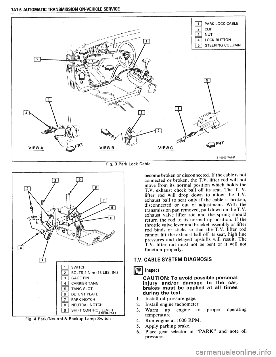
Fig. 3 Park Lock Cable
SWITCH
( BOLTS 2 N.m (18 LBS. IN.)
1 GAGE PIN
1 CARRIER TANG
1 TANG SLOT
1 DETENT PLATE
( PARK NOTCH
1 NEUTRAL NOTCH
1 SHIFT CONTROJLE$5t,-F
Fig. 4 Park/Neutral & Backup Lamp Switch
become broken or disconnected. If the cable is not
connected or broken, the
T.V. lifter rod will not
move from its normal position which holds the
T.V. exhaust check ball off its seat. The T. V.
lifter rod will drop down to allow the T.V.
exhaust ball to seat only if the cable is broken,
disconnected or out of adjustment. With the
transmission pan removed, pull down on the
T.V.
exhaust valve lifter rod and the spring should
return the rod to its normal up position. If the
throttle valve lever and bracket assembly or lifter
rod binds or sticks so that the
T.V. lifter rod
cannot lift the exhaust ball off its seat, high line
pressures and delayed upshifts will result. The
T.V. lifter rod must not be bent or it will not
function properly.
T.V. CABLE SYSTEM DIAGNOSIS
Inspect
CAUTION: To avoid possible personal
injury and/or damage to the car,
brakes must be applied at all times
during the test.
1. Install oil pressure gage.
2. Install engine tachometer.
3. Warm up engine to proper operating
temperature.
4. Run engine at 1000 RPM.
5. Apply parking brake.
6. Place gear selector in "PARK" and note oil
pressure.
Page 1609 of 1825
Adjust 2 . Filler panel 3 . Electrical connector
1 . Increase Current - Turn adjusting screw 4 . ~~l~/~~~~~
clockwise 5 . Horn
2 . Decrease Current . Turn adjusting screw
counterclockwise
Install or Connect
3 . Current adjustments should be made 1/4 turn
(90") at a time
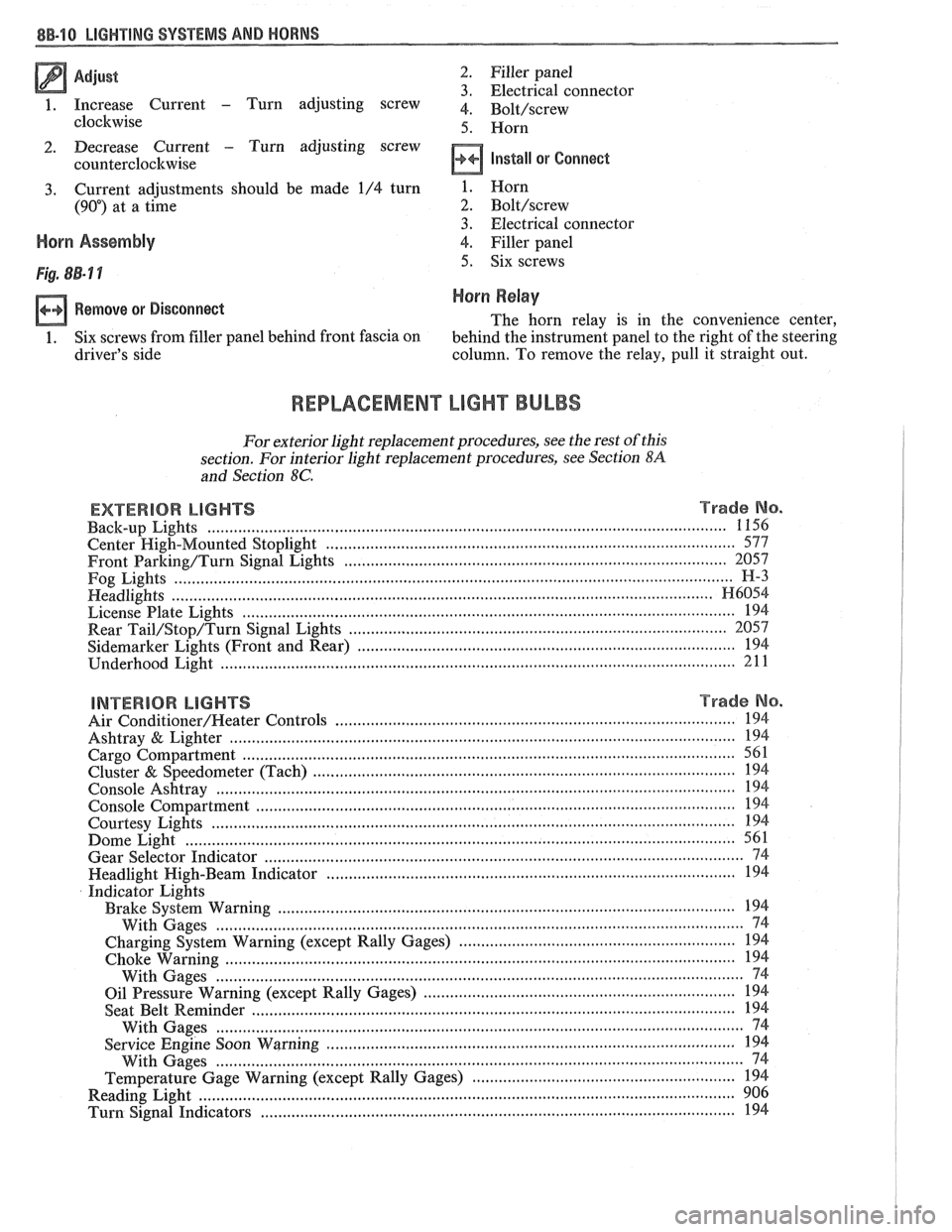
Horn Assembly
Remove or Disconnect
1 . Six screws from filler panel behind front fascia on
driver's side 1
. Horn
2 . Bolt/screw
3 . Electrical connector
4
. Filler panel
5 . Six screws
Horn Relay
The horn relay is in the convenience center.
behind the instrument panel to the right of the steering
column
. To remove the relay. pull it straight out .
REPLACEMENT LIGHT BULBS
For exterior light replacement procedures. see the rest of this
section
. For interior light replacement procedures. see Section $A
and Section 8C .
EXTERIOR LIGHTS Trade No . ...................................................................................................................... Back-up Lights 1 156
Center
High-Mounted Stoplight ............................................................................................. 577
Front Barking/Turn Signal Eights ..................................................................................... 2057
Fog Lights
............................................................................................................................... H-3
Headlights ....................................................................................................................... H6054 ................................................................................................................ License Plate Lights 194
.................................................................................... Rear Tail/Stop/Turn Signal Lights 2057
Sidemarker Lights (Front and Rear) ...................................................................................... 194 ..................................................................................................................... Underhood Light 211
BNTERBOR LIGHTS Trade No .
......................................................................................... Air Conditioner/Heater Controls 194 .................................................................................................................. Ashtray & Lighter 194 .............................................................................................................. Cargo Compartment 561
................................................................................................ Cluster & Speedometer (Tach) 194 ..................................................................................................................... Console Ashtray 194 ............................................................................................................. Console Compartment 194
Courtesy Lights
..................................................................................................................... 194 ......................................................................................................................... Dome Light 561
Gear Selector Indicator
............................................................................................................ 74 .......................................................................................... Headlight High-Beam Indicator 194
Indicator Lights
..................................................................................................... Brake System Warning 194
With Gages
........................................................................................................................ 74
............................................................... Charging System Warning (except Rally Gages) 194 .................................................................................................................... Choke Warning
194
With Gages
........................................................................................................................ 74
...................................................................... Oil Pressure Warning (except Rally Gages) 194 ............................................................................................................ Seat Belt
Reminder 194
With Gages
.................................... ... ................................................................................. 74 ............................................................................................. Service Engine Soon Warning 194
With Gages
..................................................................................................................... 74 ............................................................ Temperature Gage Warning (except Rally Gages) 194
........................................................................................................................ Reading
Light 906 ............................................................................................................ Turn Signal Indicators 194