1988 PONTIAC FIERO relay
[x] Cancel search: relayPage 439 of 1825
6C-8 ENGINE FUEL
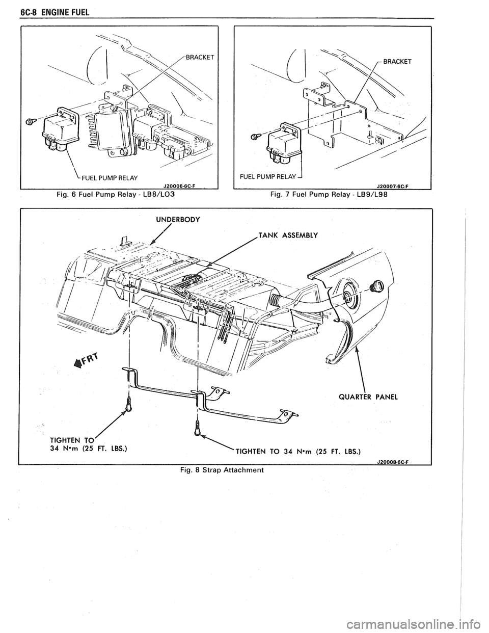
Fig. 6 Fuel Pump Relay - LB8/L03 Fig. 7 Fuel Pump Relay - LB9/L98
I UNDERBODY I
TANK ASSEMBLY
34
N*m (25 FT. LBS.)
TIGHTEN TO 34 N*m (25 FT. LBS.)
Fig. 8 Strap Attachment
Page 480 of 1825
ENGINE WIRING 605.3
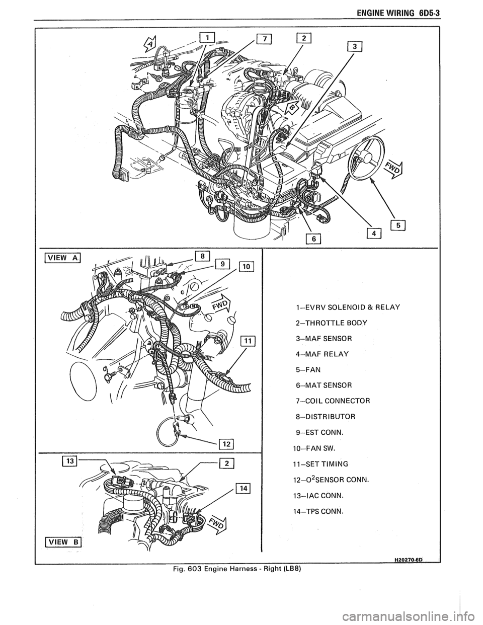
1-EVRV SOLENOID & RELAY
2-THROTTLE BODY
3-MAF SENSOR
4-MAF RELAY
6-MAT SENSOR
7-COIL CONNECTOR
8-DISTRIBUTOR 9-EST CONN.
10-FAN SW.
11-SET
TIMING
I~-O~SENSOR CONN.
13-IAC CONN.
14-TPS CONN.
Fig. 603 Engine Harness
- Right (LB8)
Page 481 of 1825
6D5-4 ENGINE WIRING
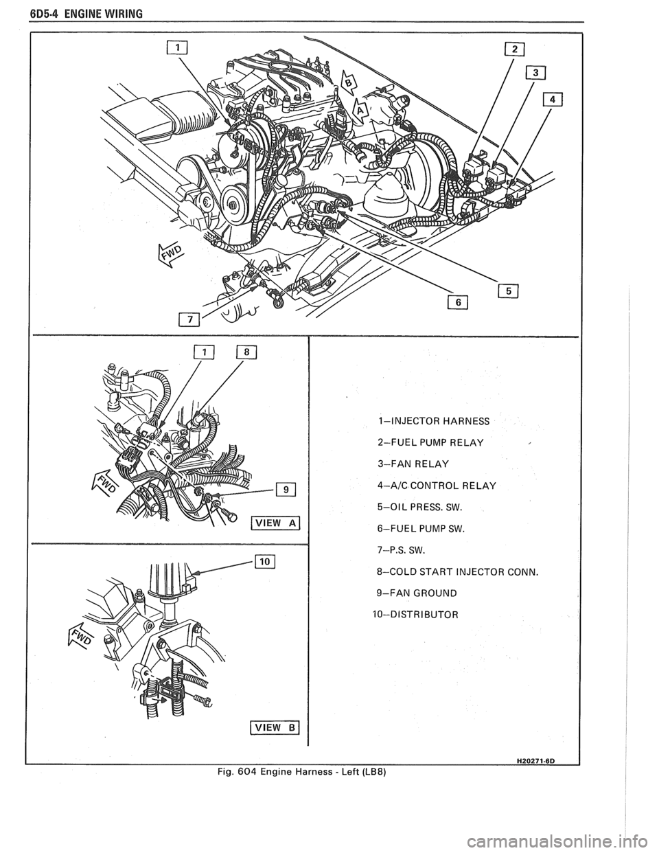
1-INJECTOR HARNESS
2-FUEL PUMP RELAY
3-FAN RELAY
4-AIC CONTROL RELAY
5-01 L PRESS. SW.
6-FUEL PUMP SW.
7-P.S. SW.
8-COLD START INJECTOR CONN.
9-FAN GROUND
Fig.
604 Engine Harness - Left (LB8)
Page 488 of 1825
DRIVEABILITY AND EMISSIONS 5.OL (VIN E) 6E2-3
........ FUEL METER COVER ASSEMBLY C2-7
FUEL INJECTOR ASSEMBLIES .......... C2-8
FUEL METER BODY ASSEMBLY ......... C2-9
..... THROTTLE POSITION SENSOR (TPS) C2-10
IDLE AIR CONTROL (IAC) VALVE ........ 62-1 1
THROTTLE BODY ASSEMBLY
.......... C2-11
MINIMUM IDLE SPEED CHECK .......... C2-12
... THROTTLE BODY INJECTION (TBI) UNIT C2-13
FUEL
HOSEIPIPE ASSEMBLIES .......... C2-13
Materials ...................... C2-13
Fuel Line Repair .................. C2-13
FUEL PUMP RELAY .................. C2-13
............... OILPRESSURESWITCH C2-13
PARTS INFORMATION ................. C2-14
Idle Air Control (IAC) Valve Check
Chart C-2C
..................... C2-16
SECTION C3
EVAPORATIVE EMISSION CONTROL SYSTEM
GENERAL DESCRIPTION
............... C3-1
........................ PURPOSE C3-1
VAPOR CANISTER
................... C3-1
EVAPORATIVE EMISSION SYSTEM
....... C3-1
IN-TANK PRESSURE CONTROL VALVE
. . C3-2
.... RESULTS OF INCORRECT OPERATION C3-2
........................ DIAGNOSIS C3-2
VISUAL CHECK OF CANISTER
.......... C3-2
CANISTER PURGE SOLENOID
.......... C3-2
ON-CAR SERVICE ................. C3-2
FUEL VAPOR CANISTER
R/R ............ C3-2
CANISTER HOSES
.................... C3-2
PARTS INFORMATION ................ C3-2
Canister Purge Valve Check
Chart C-3
...................... C3-4
SECTION
C4
IGNITION SYSTEM I EST
GENERAL DESCRIPTION
............... C4-1
PURPOSE ........................ C4-1
OPERATION ...................... C4-1
.. DIAGNOSIS ................... ... C4-1
RESULTS OF INCORRECT EST OPER ...... C4-1
HOW CODE 42 IS DETERMINED ....... C4-2
CODE12 ........................ C4-2
CHECKING EST PERFORMANCE ........ C4-2
ON-CAR SERVICE .................... C4-2
SETTINGTIMING .................. C4-2
PARTS INFORMATION ................ C4-2
Ignition System Check
Chart C-4
................... .. . C4-4
SECTION C5
ELECTRONIC SPARK CONTROL (ESC) SYSTEM
GENERAL DESCRIPTION
................ C5-1
PURPOSE ..*...................... C5-1
OPERATION
....................... C5-1
DIAGNOSIS
......................... C5-1
RESULTS OF INCORRECT ESC OPERATION
. C5-1
ON-CAR SERVICE
..................... C5-1 ESC
KNOCK SENSOR
................ C5-1
ESCMODULE
...................... C5-1
PARTS INFORMATION ................. C5-2
Electronic Spark Control (ESC) System Check
Chart C-5
...................... C5-4
SECTION C6
AIR INJECTION REACTION (A.I.R.) SYSTEM
GENERAL DESCRIPTION
............... C6-1
PURPOSE
.*....................... C6-1
OPERATION
...................... C6-1
AIR CONTROL PEDES VALVE .......... C6-1
RESULTS OF INCORRECT OPERATION
.... C6-2
DIAGNOSIS
........................ C6-2
OPERATIONAL CHECKS
.....*........ C6-2
AirPump ...................... C6-2
Hoses and Pipes
................. C6-3
Check Valve
.................... C6-3
ON-CAR SERVICE
.................... C6-3
DRIVEBELT ...................... C6-3
AIR INJECTION PUMP
............... C6-3
AIR INJECTION CONTROL
(PEDES) VALVE
.................. C6-3
AIR INJECTION CHECK VALVE ......... C6-4
PARTS INFORMATION
................ C6-4
AIR Management Check
. Pedes Valve
Chart C-6
..................... C6-6
SECTION C7
EXHAUST GAS RECIRCULATION (EGR) SYSTEM
GENERAL DESCRIPTION
............... C7-1
PURPOSE
........................ C7-1
OPERATION
...................... C7-1
EGRCONTROL
..................... C7-1
NEGATIVE BACKPRESSURE VALVE
...... C7-1
EGR VALVE IDENTIFICATION
.......... C7-2
RESULTS OF INCORRECT OPERATION
.... C7-2
DIAGNOSIS
......................... C7-2
ON-CAR SERVICE
..................... C7-2
EGRVALVE
....................... C7-2
EGR Manifold Passage
............. C7-2
EGR CONTROL SOLENOID
............. C7-3
PARTS INFORMATION
................. C7-3
Exhaust Gas Recirculation (EGR) Check
Chart C-7
...................... C7-4
SECTION
C8
TRANSMISSION CONVERTER CLUTCH
GENERAL DESCRIPTION
............... C8-1
PURPOSE
........................ C8-1
OPERATION
...................... C8-1
CIRCUIT DESCRIPTION
............... C8-1
RESULTS OF INCORRECT TCC
OPERATION
..................... C8-2
DIAGNOSIS
......................... C8-2
ON-CAR SERVICE .................... C8-2
PARTS INFORMATION ................. C8-2
Page 493 of 1825
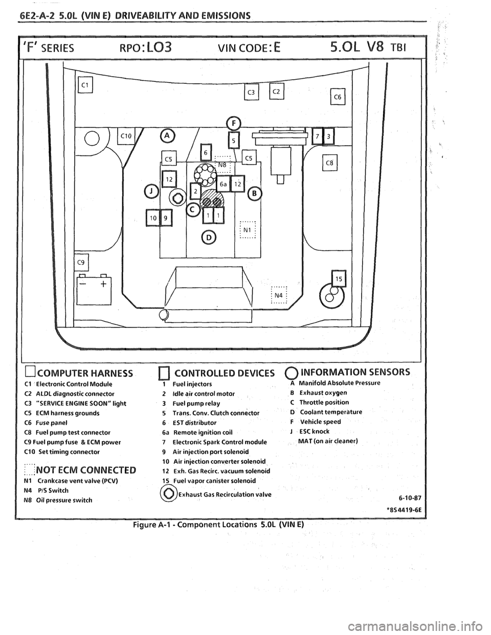
6E2-A-2 5.OL (VIN E) DRIVEABILIW AND EMISSIONS
IFf SERIES VIN CODE: E
OCOMPUTER HARNESS
C1 Electronic Control Module
C2 ALDL diagnostic connector
C3 "SERVICE ENGINE SOON" light
C5 ECM harness grounds
C6 Fuse panel
C8 Fuel pump test connector
C9 Fuel pump fuse & ECM power
C10 Set timing connector
....,
: . ... 'NOT ECM CONNECTED
N1 Crankcase vent valve (PCV)
N4 PIS Switch
N8 Oil pressure switch
[7 CONTROLLED DEVICES 0 INFORMATION SENSORS
1 Fuel injectors A Manifold Absolute Pressure
2 Idle air control motor B Exhaust oxygen
3 Fuel pump relay
C Throttle position
5 Trans. Conv. Clutch connector
D Coolant temperature
6 EST distributor
F Vehicle speed
6a Remote ignition coil
J ESCknock
7 Electronic Spark Control module MAT (on air cleaner)
9 Air injection port solenoid
10 Air injection converter solenoid
12 Exh. Gas Recirc. vacuum solenoid
15 Fuel vapor canister solenoid
Exhaust Gas Recirculation valve
6-1
0-87
Figure A-I - Component Locations 5.OL (VIN E)
Page 501 of 1825

6EZ-A-10 5.0L (VIN E) DRIVEABILITY AND EMISSIONS
TO OIL PRESS. SW.
&FUEL PUMP RELAY
BATTERY
12 V
. . . . . . . . FUSIBLE LINK 15 WAY
439 PNWBLK
419
BRNNVHT
SERIAL DATA
451
WHTIBLK
450 BLWHT
ALDL CONNECTOR
NO "SERVICE ENGINE SOON" "LIGHT
5.OL (VIN E) "F'" SERIES (TBI)
Circuit Description:
There should always be a steady "Service Engine Soon" light, when the ignition is "ON" and engine stopped.
Battery is supplied directly to the light bulb.
The electronic control module (ECM) will control the light and
turn it "ON" by providing a ground path through CKT 419 to the ECM.
Test Description: Numbers below refer to circled
numbers on the diagnostic chart.
1. Battery feed CKT 340 is protected by a
20amp in-
line fuse. If this fuse was blown, refer to wiring
diagram on the facing page of Code 54.
2. Using a test light connected to 12 volts, probe each
of the system ground circuits to be sure
a good
ground is present. See ECM terminal end view in
front of this section for ECM pin locations of
ground circuits.
Diagnostic Aids:
Engine runs ok, check:
@ Faulty light bulb
@ CKT419open
@ Gage fuse blown. This will result in no oil, or
generator lights, seat belt reminder, etc.
Engine cranks, but will not run.
@ Continuous battery - fuse or fusible link open.
@ ECM ignition fuse open.
@ Battery CKT 340 to ECM open.
o Ignition CKT 439 to ECM open.
@ Poor connection to ECM.
Page 503 of 1825

6E2-A-12 5.OL (VIN E) DRIVEABILITY AND EMISSIONS
TO OIL PRESS. SW. ECM
&FUEL PUMP RELAY
FUSE
& HOLDER BATTERY 12 V . . . . . . . .
FUSIBLE LINK
439
PNWBLK
419 BRNNVHT
- -
451 WHTIBLK
450
BLWHT
ALDL CONNECTOR
8-4-87
55 1235-6E
CHART A-2
NO ALDL DAM OR WON"T FLASH CODE 12
'SERVICE ENGINE SOON" LLlGHT "ON" "STEADY
5.OL (VIN E) "F" "SERIES (TBI)
Circuit Description:
There should always be a steady "Service Engine Soon" light, when the ignition is "ON" and engine stopped.
Battery is supplied directly to the light bulb. The electronic control module
(ECM) will turn the light "ON" by
grounding CKT 419 at the ECM.
With the diagnostic terminal grounded, the light should flash
a Code 12, followed by any trouble code(s)
stored in memory.
A steady light suggests a short to ground in the light control CKT 419, or an open in diagnostic CKT 451.
Test Description: Numbers below refer to circled
numbers on the diagnostic chart.
1. If there is a problem with the ECM that causes
a
"Scan" tool to not read serial data, then the ECM
should not flash a Code
12. If Code 12 does flash,
be sure that the "Scan" tool is working properly on
another vehicle. If the "Scan" is functioning
properly and CKT 461 is OK, the PROM or ECM
may
be at fault for the NO ALDL symptom.
2. If the light goes "OFF" when the ECM connector is
disconnected, then CKT 419 is not shorted to
ground.
3. This step will check for an open diagnostic CKT
45 1.
4. At this point, the "Service Engine Soon" light
wiring is OK. The problem is a faulty ECM or
PROM. If Code 12 does not flash, the ECM should
be replaced using the original PROM. Replace the
PROM only after trying an ECM, as a defective
PROM is an unlikely cause of the problem.
Page 509 of 1825
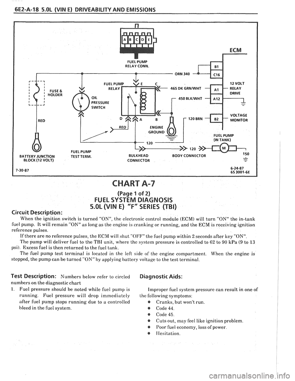
6EZ-Pa-18 5.OL (VIN E) DRIVEABILITY AND EMISSIONS
FUEL PUMP
RELAY CONN.
465 DK GRNMIHT
450 BLWHT
FUEL PUMP
BATTERY JUNCTION TEST TERM. BULKHEAD BODY CONNECTOR
BLOCK
(1 2 VOLT) CONNECTOR
CHART A-7
(Page 1 of 2)
FUEL SYSTEM DlAGNOSlS
5.0L (VIN E) "F"" SERIES (TBI)
Circuit Description:
When the ignition switch is turned "ON", the electronic control module (ECM) will turn "ON" the in-tank
fuel pump. It will remain "ON"
as long as the engine is cranking or running, and the ECM is receiving ignition
reference pulses.
If there are no reference pulses, the ECM will shut
"OI'F" the fuel pump within 2 seconds after key "ON".
The pump will deliver fuel to the THI unit, where the system pressure is controlled to 62 to 90 kPa (9 to 13
psi). Excess fuel is then returned to the fuel tank.
The fuel pump test terminal is located in the left side of the engine compartment. When the engine is
stopped, the pump can be turned "ON" by applying battery voltage to the test terminal.
lest Description: Numbers below refer to circled Diagnostic Aids:
numbers on the diagnostic chart
1. Fuel pressure should be noted while fuel pump is Improper fuel system pressure can result in one of
running. Fuel pressure will drop immediately the following symptoms:
after fuel pump stops running due to a controlled
e Cranks, but won't run.
bleed in the fuel system.
@ Code 44.
@ Code 45.
@ Cuts out, may feel like ignition problem.
@ Poor fuel economy, loss of power.
FIesitation.