1988 PONTIAC FIERO relay
[x] Cancel search: relayPage 1639 of 1825
8E -12 WINDSHIELD WIPER SYSTEMS. F CAWLINE
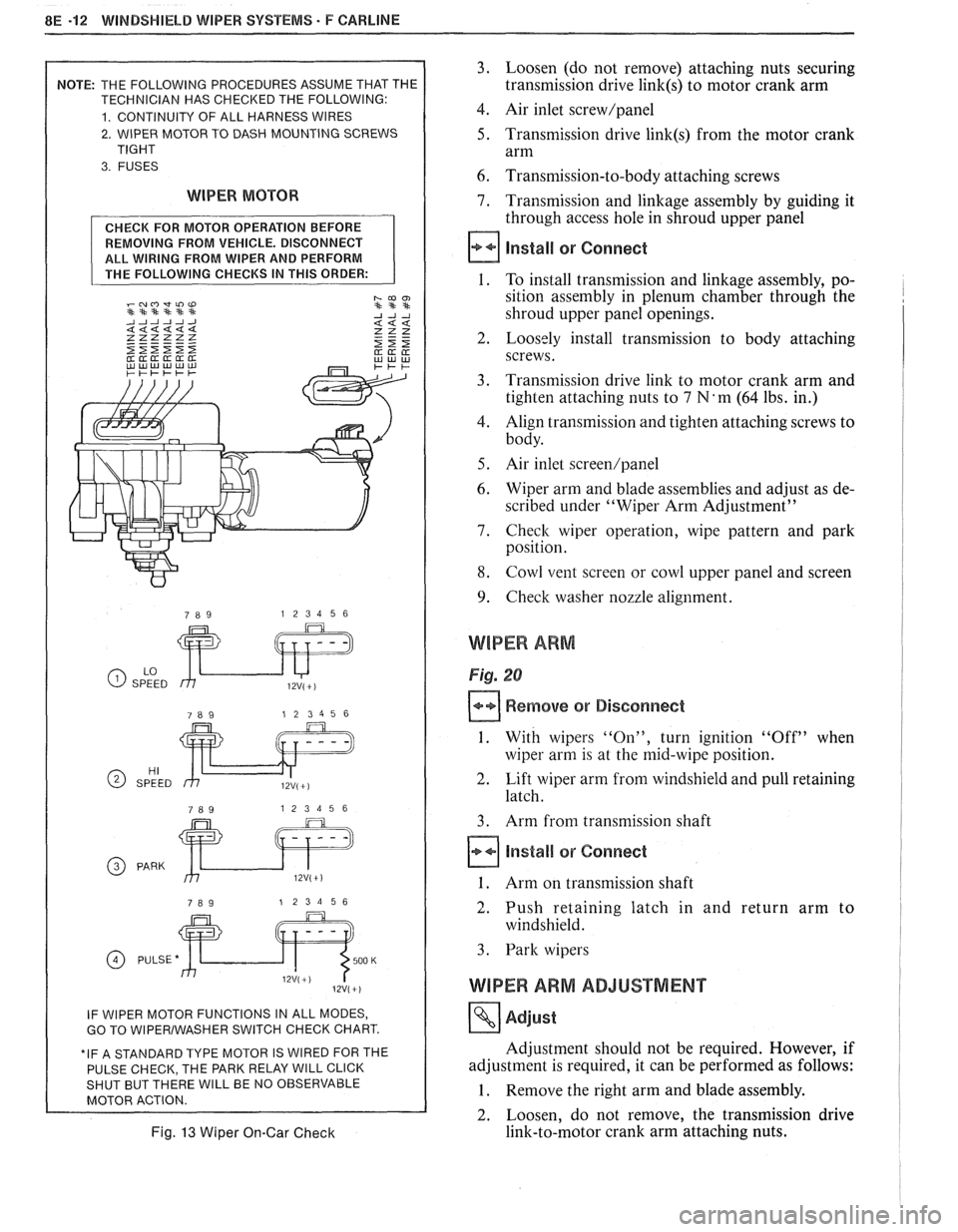
2. WIPER MOTOR TO DASH MOUNTING SCREWS
WIPER MOTOR
REMOVING FROM VEHICLE. DISCONNECT
ALL WIRING FROM WIPER AND PERFORM
GO TO WlPERlWASHER SWITCH CHECK CHART.
E PARK RELAY
WlLL CLICK WlLL BE NO OBSERVABLE
Fig. 13 Wiper On-Gar Check
3. Loosen (do not remove) attaching nuts securing
transmission drive
link(s) to motor crank arm
4. Air inlet screw/panel
5. Transmission drive link(s) from the motor crank
arm
6. Transmission-to-body attaching screws
7. Transmission and linkage assembly by guiding it
through access hole in shroud upper panel
install or Connect
1. To install transmission and linkage assembly, po-
sition assembly in plenum chamber through the
shroud upper panel openings.
2. Loosely install transmission to body attaching
screws.
3. Transmission drive link to motor crank arm and
tighten attaching nuts to
7 N'm (64 lbs. in.)
4. Align transmission and tighten attaching screws to
body.
5. Air inlet screen/panel
6. Wiper arm and blade assemblies and adjust as de-
scribed under "Wiper Arm Adjustment"
7. Check wiper operation, wipe pattern and park
position.
8. Cowl vent screen or cowl upper panel and screen
9. Check washer nozzle alignment.
WIPER ARM
Fig. 20
Remove or Disconnect
1. With wipers "On", turn ignition "Off" when
wiper arm is at the mid-wipe position.
2. Lift wiper arm from windshield and pull retaining
latch.
3. Arm from transmission shaft
Install or Connect
1. Arm on transmission shaft
2. Push retaining latch in and return arm to
windshield.
3. Park wipers
WIPER ARM ADJUSTMENT
Adjust
Adjustment should not be required. However, if
adjustment is required, it can be performed as follows:
1. Remove the right arm and blade assembly.
2. Loosen, do not remove, the transmission drive
link-to-motor crank arm attaching nuts.
Page 1645 of 1825
8E -18 WINDSHIELD WIPER SYSTEMS. F CAWLINE
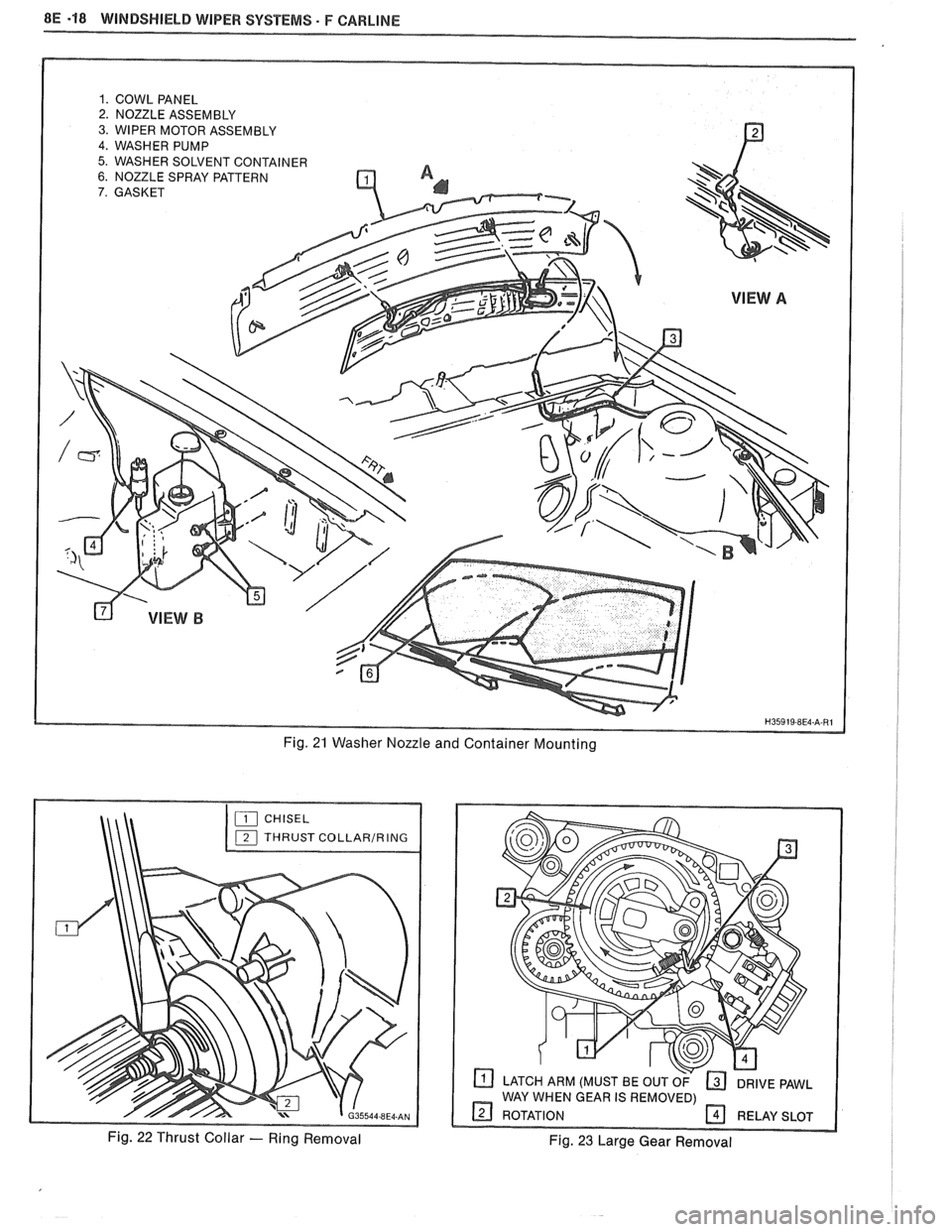
1. COWL PANEL 2. NOZZLE ASSEMBLY
3. WIPER MOTOR ASSEMBLY
4. WASHER PUMP
5. WASHER SOLVENT CONTAINER 6. NOZZLE SPRAY PATTERN
7. GASKET
Fig. 21 Washer Nozzle and Container Mounting
CHISEL
THRUST
COLLARIRING
Fig. 22 Thrust Collar - Ring Removal
LATCH ARM (MUST BE OUT OF DRIVE PAWL
WAY WHEN GEAR IS REMOVED)
9 ROTATION RELAY SLOT
Fig. 23 Large Gear Removal
Page 1659 of 1825
9A-10 RADIO SYSTEMS AND ANTENNAS
ANTENNA
Figure 609
Diagnosis is covered in the general description at
the front of this section.
Remove or Disconnect
1. Negative battery cable.
2. Right side lower instrument close out panel.
3. Antenna connection at radio.
4. Power antenna: Disconnect instrument panel
harness from radio and, using tool
J 28742 or
equivalent, remove power antenna wire from connector. Remove right
lower instrument close
out panel and disconnect power antenna relay.
5. Raise car and remove fender wheelhouse panel ,
(see Section 2C).
6. Mast escution.
7. Mast or motor assembly bracket screws.
8. Grommet from kick-panel bulkhead and
carefully pull harness from car interior.
9. Lower antenna assembly from fender well.
Install or Connect
Reverse removal procedure to install.
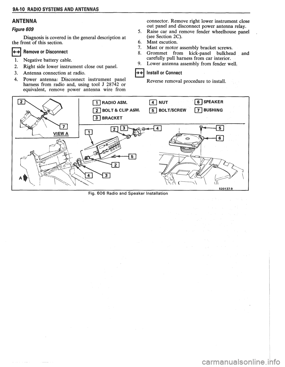
Fig. 606 Radio and Speaker Installation
Page 1660 of 1825
RADIO SYSTEMS AND ANTENNAS 9A.11
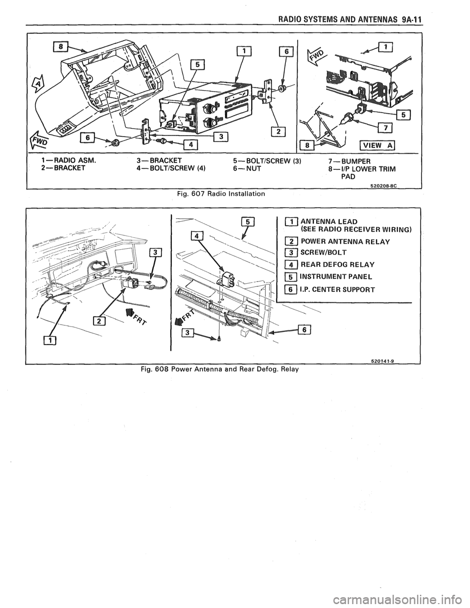
1 --RADIO ASM. 3- BRACKET 5- BOLTISCREW (3) 7-BUMPER
2 - BRACKET 4- BOLTISCREW (4) 6-NUT 8- IIP LOWER TRIM
PAD
Fig.
607 Radio Installation
ANTENNA LEAD
(SEE RADIO RECEIVER WIRING)
REAR DEFOG RELAY
INSTRUMENT PANEL
Fig.
608 Power Antenna and Rear Defog. Relay
Page 1678 of 1825
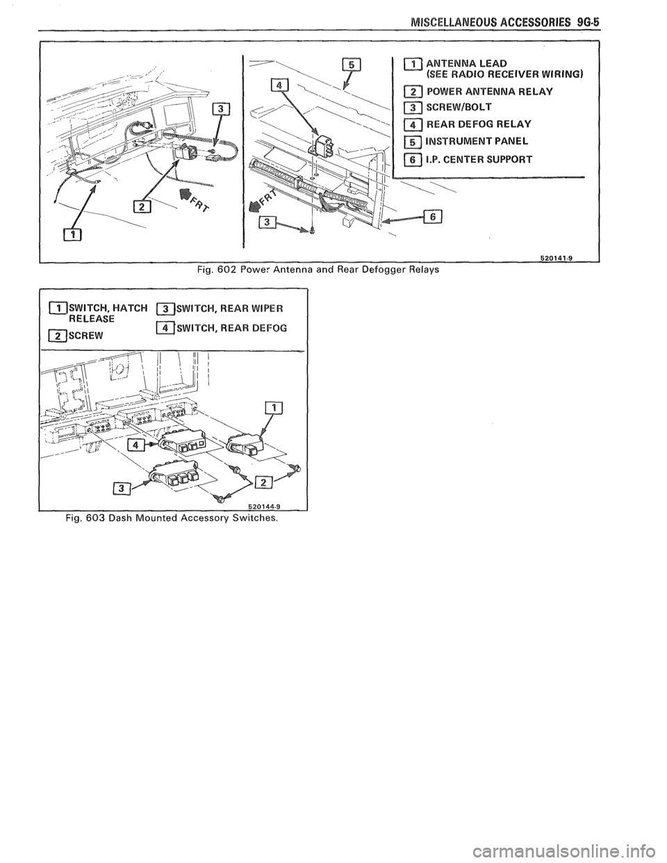
MISCELLANEOUS ACCESSORIES 9G-5
ANTENNA LEAD
(SEE RADIO RECEIVER WIRING)
POWER ANTENNA RELAY
SCREWIBOLT
REARD DEFOG RELAY
INSTRUMENT PANEL
11 I.P. CENTER SUPPORT XJ I
Fig. 602 Powe: Antenna and Rear Defogger Relays
SWITCH, HATCH SWITCH, REAR WIPER 1 RELEASE - I ~SWITCW, REAR BEFOG
I
1 520144-9
Fig. 603 Dash Mounted Accessory Switches.
Page 1794 of 1825
SEATS - F STYLE 9N-11
Removal
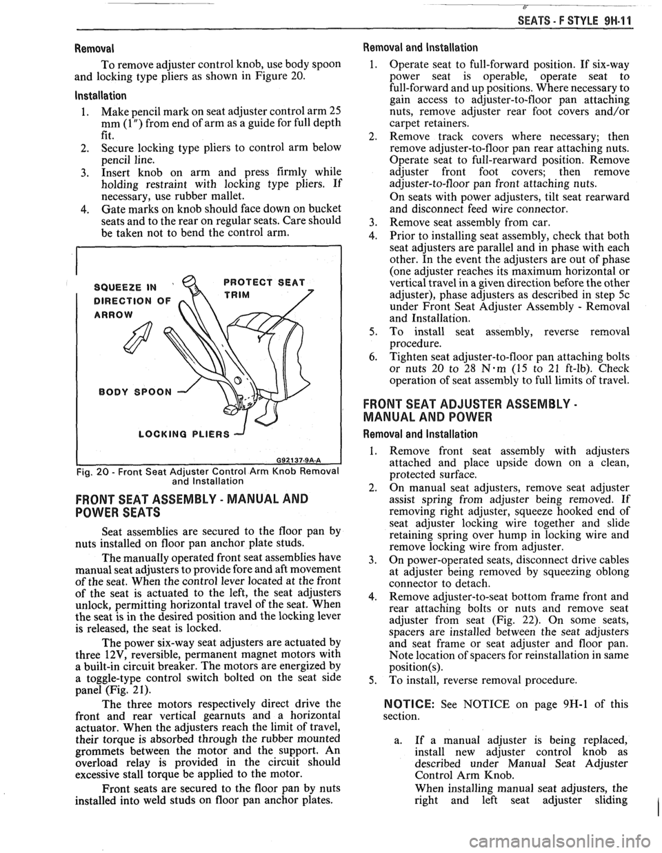
To remove adjuster control knob, use body spoon
and locking type pliers as shown in Figure 20.
lnstallation
1. Make
pencil mark on seat adjuster control arm 25
mm
(1 ") from end of arm as a guide for full depth
fit.
2. Secure locking type pliers
to control arm below
pencil line.
3. Insert knob on arm and press firmly while
holding restraint with locking type pliers. If
necessary, use rubber mallet.
4. Gate marks on knob should face down on bucket
seats and to the rear on regular seats. Care should
be taken not to bend the control arm.
SQUEEZE IN '
DIRECTION OF
ARROW PROTECT
SEAT
TRIM
BODY
SPOON \\.,
I
LOCKING PLIERS -J
I
Fig. 20 - Front Seat Adjuster Control Arm Knob Removal
and lnstallation
FRONT SEAT ASSEMBLY - MANUAL AND
POWER SEATS
Seat assemblies are secured to the floor pan by
nuts installed on floor pan anchor plate studs.
The manually operated front seat assemblies have
manual seat adjusters to provide fore and aft movement
of the seat. When the control lever located at the front
of the seat is actuated to the left, the seat adjusters
unlock, permitting horizontal travel of the seat. When
the seat is in the desired position and the locking lever
is released, the seat is locked.
The power six-way seat adjusters are actuated by
three
12V, reversible, permanent magnet motors with
a built-in circuit breaker. The motors are energized by
a toggle-type control switch bolted on the seat side
panel (Fig. 2
1).
The three motors respectively direct drive the
front and rear vertical
gearnuts and a horizontal
actuator. When the adjusters reach the limit of travel,
their torque is absorbed through the rubber mounted
grommets between the motor and the support. An
overload relay is provided in the circuit should
excessive stall torque be applied to the motor.
Front seats are secured to the floor pan by nuts
installed into weld studs on floor pan anchor plates.
Removal and lnstallation
1. Operate seat to full-forward position. If six-way
power seat
is operable, operate seat to
full-forward and up positions. Where necessary to
gain access to adjuster-to-floor pan attaching
nuts, remove adjuster rear foot covers and/or
carpet retainers.
2. Remove track covers where necessary; then
remove adjuster-to-floor pan rear attaching nuts.
Operate seat to full-rearward position. Remove
adjuster front foot covers; then remove
adjuster-to-floor pan front attaching nuts.
On seats with power adjusters, tilt seat rearward
and disconnect feed wire connector.
3. Remove seat assembly from car.
4. Prior to installing seat assembly, check that both
seat adjusters are parallel and in phase with each
other. In the event the adjusters are out of phase
(one adjuster reaches its maximum horizontal or
vertical travel in a given direction before the other
adjuster), phase adjusters as described in step
5c
under Front Seat Adjuster Assembly - Removal
and Installation.
5. To install seat assembly, reverse removal
procedure.
6. Tighten seat adjuster-to-floor pan attaching bolts
or nuts 20 to 28
N.m (15 to 21 ft-lb). Check
operation of seat assembly to full limits of travel.
FRONT SEAT ADJUSTER ASSEMBLY -
MANUAL AND POWER
Removal and lnstallation
1. Remove front seat assembly with adjusters
attached and place upside down on a clean,
protected surface.
2. On manual seat adjusters, remove seat adjuster
assist spring from adjuster being removed. If
removing right adjuster, squeeze
hooked end of
seat adjuster locking wire together and slide
retaining spring over hump in locking wire and
remove locking wire from adjuster.
3. On power-operated seats, disconnect drive cables
at adjuster being removed by squeezing oblong
connector to detach.
4. Remove adjuster-to-seat bottom frame front and
rear attaching bolts or nuts and remove seat
adjuster from seat (Fig. 22). On some seats,
spacers are installed between the seat adjusters
and seat frame or seat adjuster and floor pan.
Note location of spacers for reinstallation in same
position(s).
5. To install, reverse removal procedure.
NOTICE: See NOTICE on page 9H-1 of this
section.
a. If a manual adjuster is being replaced,
install new adjuster control knob as
described under Manual Seat Adjuster
Control Arm Knob.
When installing manual seat adjusters, the
right and left seat adjuster sliding
I
Page 1801 of 1825
9H-18 SEATS - F STYLE
Adjuster assembly (23, Fig. 28).
Disconnect hoses from solenoid valve
(1, Fig. 29).
Head restraint (ref. Head Restraint procedures).
Boot (12, Fig. 28)
Screws from underside of
seatback outer panel
(13) and lift off panel
Inner panel (15)
Seatback trim cover (26)
Seatback pad (27)
Lateral bladders and hose assembly (19).
Lumbar panel
(22), lumbar bladder and hose
assembly (2 1)
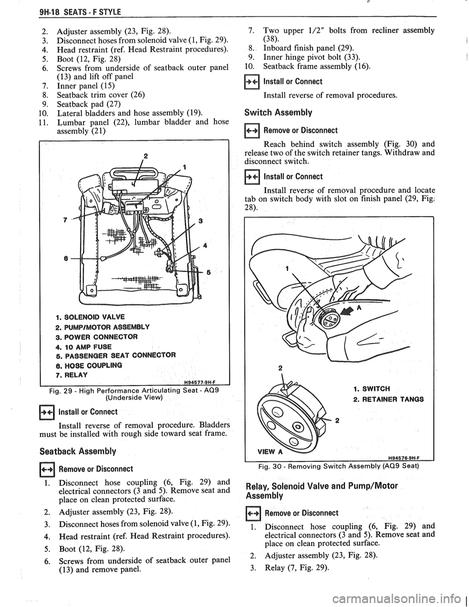
1. SOLENOID VALVE
2.
PUMPIMOTOR ASSEMBLY
3. BOWER CONNECTOR
4. 10 AMP FUSE
6. PASSENGER SEAT CONNECTOR
8. HO9E COUPLING
7. RELAY H94577-9H-F
Fig. 29 - High Performance Articulating Seat - AQ9 (Underside View)
Install or Connect
Install reverse of removal procedure. Bladders
must be installed with rough side toward seat frame.
Seatback Assembly
Remove or Disconnect
1. Disconnect hose coupling (6, Fig. 29) and
electrical connectors (3 and 5). Remove seat and
place on clean protected surface.
2. Adjuster assembly (23, Fig. 28).
3. Disconnect hoses from solenoid valve (1, Fig. 29).
4. Head restraint (ref. Head Restraint procedures).
5. Boot (12, Fig. 28).
6. Screws from underside of seatback outer panel
(1 3) and remove panel. 7.
Two upper
1/2" bolts
from recliner assembly
(38). I
8. Inboard finish panel (29).
9. Inner hinge pivot bolt (33).
I
10. Seatback frame assembly (16).
Install or Connect
Install reverse of removal procedures.
Switch Assembly
Remove or Disconnect
Reach behind switch assembly (Fig. 30) and
release two of the switch retainer tangs. Withdraw and
disconnect switch.
Install or Connect
Install reverse of removal procedure and locate
tab on switch body with slot on finish panel (29, Fig!
28).
1. SWITCH
2. RETAINER TANGS
2
Fig. 30 - Removing Switch Assembly (AQ9 Seat)
Relay, Solenoid Valve and Pump/Motor
Assembly
Remove or Disconnect
1. Disconnect hose coupling (6, Fig. 29) and
electrical connectors (3 and 5). Remove seat and
place on clean protected surface.
2. Adjuster assembly (23,
Fig. 28).
3. Relay (7, Fig. 29).
Page 1818 of 1825
Battery .......................................................... 6D1-2
Brakes
.................................................................. 5-3
................................ Bumper. Energy Absorber 2B-2
........................................... Charging System 6D3- 1
........................................ Cooling and Radiator 6B-3
....................... ................ Cranking System .. 6D2- 1
Cruise Control
................................. 9B-4, 8A-34-0
......................................... Drive Axles (Rear) 4B1-2
Engine Performance
......................................... 6-3
.............................................. Ignition System 6D4-3
Instrument Panel, Gages and
.................................................... Console 8C-3
............................. Miscellaneous Accessories 9G-2
............................................... Power Antenna 9A-2
Power Recirculation Ball
.................................. 3-3
Power Steering Pumps
........................................ 3-4
.............................................. Propeller Shaft 4A- 1
................................................................ Radio 9A-1
.............. Seal Replacement Recommendations 3- 10
........................ . Steering Gear and Pump Leaks 3-10
.............. Strut Dampener and Shock Absorber 3- 12
.................................................... Trim
Height 3- 14
.................................................. Steering Linkage 3-3
Steering, Suspension, Tires and
Wheels
.............................. .. ................. Section 3
Steering Wheels and Columns
............................ 3-4 ......................................................... Vibrations 3- 14
................................................. Wheel Bearing 3-14 .............................................. Wheels and Tires 3- 13
........................... Windshield Wiper System 8El-2
............................................. Digital Cloclc 8A- 150-0
Disc Brake Caliper Assembly
.......................................... (3000/3 100 Series) 5B1
............... ................... General Description .. 5B 1-2 ............................................... On-Car Service 5B 1-2
...................................... Caliper Assembly 5B 1-2
.......................... Shoe and Lining Assembly 5B 1-4
...................................................... Unit Repair
5B 1-4
.......................................... Caliper Overhaul 5B 1-4
?isc Brake Caliper Assembly (3548
Series)
............................................................. 5B6
General Description
....................................... 5B6-2
On-Car Service
............................................... 5B6-2
....................................... Caliper Assembly 5B6-2
.......................... Parking Brake Adjustment 5B6-3
.......................... Shoe and Lining Assembly 5B6-4
Unit Repair
............................... ... .................... 5B6-5
Caliper Overhaul
.......................................... 5B6-5
.......................... Door Lock Relay (Circuit) 8A- 130-0
Driveability and Emissions
........................ Section 6E
Fuel Injection (Port)
..................................... 6E3-1
Index
................................... follows 6E3-(213-2
...................................... Fuel Injection (TB 1) .6E
2- 1
...................................... Index follows 6E2-C 14-4
Drum Brake Assembly
................... ......... Section 5C3
General Description
......................... ... ............ 5C3-1
........................................... On-Car Service 5C3- 1
Backing Plate
........................................ 5C3-7
....................................... Brake Adjustment .5C 3-4
..................................... Brake Components 5C3-1
Parking Brake Adjustment
.......................... 5C3-4
Wheel Cylinder ........................................... 5C3-5 ..................................................... Unit Repair 5C3-7
............................ Wheel Cylinder Overhaul 5C3-7
CHASSIS INDEX m3
E
........................ Electric Rear Window Defogger 9G-2 ............................................ Electrical Diagnosis 88-1
Audible Alarms .............................................. 81%-77
.......................................... Component Data 818-201
.................................................... Headlights 8A- 100
........................ Heating and Air Conditioning 8A-60 .............................................................. Index $A- 1
........................................... Instrument Panel .8 A-82
.................................................. Introduction 8A-2
........................................................... Lights .8 A- 100
............................................ Repair Procedure 88-5 ........................................ Seats and Mirrors 8A- 141
......................................................... Symbols 8A-3
Troubleshooting Procedures ............................ 8A-4
.................................................. ... Windows .. .8 A- 120
............................................... Wiper/Washers .8 A-90
Electronic Glare Control Mirror
........................ 9G-4
.......................... Electronic Instrument Cluster 86-4, 6
Emissions and Driveability
....................................... Fuel Injection (Port) 6E3- 1
....................................... Fuel Injection (TB1) 6E2-1
Engine
.... V-6 2.8L VIN CODE S RPO (LB8) Section 6A2
.... V-8 5.OL VIN E and F, 5.7L VIN 8 Section 6A3
................................................. Cooling Section 6B
Engine Specifications
............................................................ V-6 6A2-26
............................................................. V-8 683-28
General Description
.............................................................. V-6 61 ............................................................. V-8 6A3-1
Lubrication System ........................................................... V-6 ..6A 2- 1
................................................................ V-8 6A3-2
Multi-port Fuel Injection
..................................................... VIN S 8A-20-0
................................................. VIN 8 8A-23-0
............ Throttle Body Injection (VIN E) 8A-22-0
................ Tuned Port Injection (VIN F) 8A-2 1-0
On-Vehicle Service Camshaft
......................................................... V-6 6A2-16
................................ ..................... V-8 .. 6A3-16
Camshaft Bearings
......................................................... V-6 6A2-16
...................................................... V-8 ..6A 3-17
Connecting Rod Bearings
......................................................... V-6 .6A 2- 18
................................................... V-8 6A3-13
...................... Crankcase (Front Cover) .6A
2- 15
............ Crankcase/Camshaft Sensors Section 6E3
Crankshaft
....................................................... V-6 6A2-25
......................................................... V-8 .6A 3-28
......................................... Cylinder Block .6A 3-26
Cylinder Head
.......................................................... V-6 682-12
.......................................................... V-8 6A3-11
Dipstick Tube .............................................. 6A3-7
Engine Assembly
....................................................... V-6 6212
.......................................................... V-8 6A3-27
Exhaust Manifold
........................................................ V-6 .6A 2-9
V-8
....................................................... 6A3-7