1988 PONTIAC FIERO power steering fluid
[x] Cancel search: power steering fluidPage 195 of 1825
387-2 POWER STEERING
The effect of improperly adjusted worm thrust
bearings or an improperly adjusted over-center preload
could cause a handling stability complaint.
To properly adjust the power steering gear, the
assembly MUST be removed from the vehicle and
adjustments performed as outlined.
For removal of the power steering gear assembly
see "Power Steering Gear".
DRIVE BELT TENSION
All drive belt tension specifications can be found
in the Engine Cooling Section 6B.
When adjusting a power steering pump belt,
never pry against the pump reservoir or pull against the
filler neck. Two systems are used for belt adjustment.
On some
models, the pump is loosened from the
bracket and moved outward to increase the tension. On
other models, a half-inch square drive hole is located
in the bracket, and this hole is used to rotate the
pump-and-bracket assembly outward to increase belt
tension.
Place belt tension gage, J-23600 or equivalent
midway between the pulleys on drive belt being
checked.
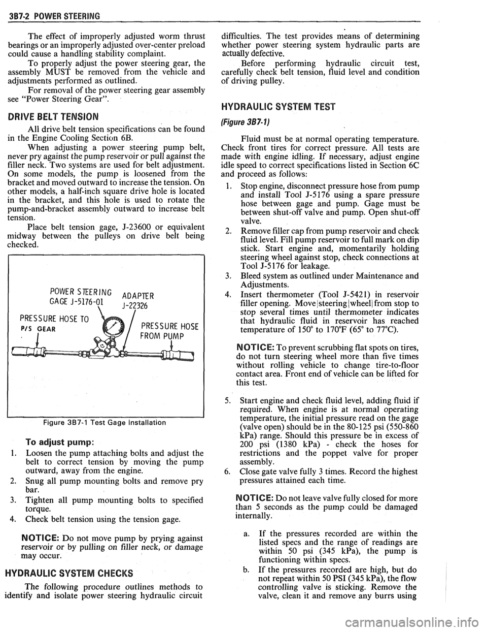
POWER SKERING ADAPER GAGE J-5176-01 J-22326
PRESSURE HOSE TO
P/S GEAR PRESSURE HOSE
Figure 387-1 Test Gage Installation
To adjust pump:
1.
Loosen the pump attaching bolts and adjust the
belt to correct tension by moving the pump
outward, away from the engine.
2. Snug all pump mounting bolts and remove pry
bar.
3. Tighten all pump mounting bolts to specified
torque.
4. Check belt tension using the tension gage.
NOTICE: Do not move pump by prying against
reservoir or by pulling on filler neck, or damage
may occur.
HYDRAULIC SYSTEM CHECKS
The following procedure outlines methods to
identify and isolate power steering hydraulic circuit difficulties.
The test provides means of determining
whether power steering system hydraulic parts are
actually
defective.
Before performing hydraulic circuit test,
carefully check belt tension, fluid level and condition
of driving pulley.
HYDRAULIC SYSTEM TEST
(Figure 387- lj
Fluid must be at normal operating temperature.
Check front tires for correct pressure. All tests are
made with engine idling. If necessary, adjust engine
idle speed to correct specifications listed in Section 6C
and proceed as follows:
1. Stop engine, disconnect pressure hose from pump
and install Tool
5-5176 using a spare pressure
hose between gage and pump. Gage must be
between shut-off valve and pump. Open shut-off
valve.
2. Remove filler cap from pump reservoir and check
fluid level. Fill pump reservoir to full mark on dip
stick. Start engine and, momentarily holding
steering wheel against stop, check connections at
Tool J-5 176 for leakage.
3. Bleed system as outlined under Maintenance and
Adjustments.
4. Insert thermometer (Tool J-5421) in reservoir
filler opening. Move
/steering (wheel/ from stop to
stop several times until thermometer indicates
that hydraulic fluid in reservoir has reached
temperature of
150" to 170°F (65" to 77°C).
N OTI G E: To prevent scrubbing flat spots on tires,
do not turn steering wheel more than five times
without rolling vehicle to change tire-to-floor
contact area. Front end of vehicle can be lifted for
this test.
5. Start engine and check fluid level, adding fluid if
required. When engine is at normal operating
temperature, the initial pressure read on the gage
(valve open) should be in the 80-125 psi (550-860
kPa) range. Should this pressure be in excess of
200 psi (1380
kPa) - check the hoses for
restrictions and the poppet valve for proper
assembly.
6. Close gate valve fully
3 times. Record the highest
pressures attained each time.
N OTI C E: Do not leave valve fully closed for more
than
5 seconds as the pump could be damaged
internally.
a. If
the pressures recorded are within the
listed specs and the range of readings are
within 50 psi (345
kPa), the pump is
functioning within specs.
b. If the pressures recorded are high, but do
not repeat within 50 PSI (345
kPa), the flow
controlling valve is sticking. Remove the
valve, clean it and remove any burrs using
Page 196 of 1825
POWER STEERING 387-3
crocus cloth or fine hone. If the system 4. If the pump checks within specifications, leave
contains some dirt, flush it. If it is the valve open and turn (or have turned) the
exceptionally dirty, both the pump and the steering wheel into both corners. Record the
gear must be completely disassembled, highest pressures and compare with the
cleaned, flushed and reassembled before maximum pump pressure recorded. If this
further usage. pressure cannot be built in either (or one) side of
- the gear, the gear is leaking internally and must
c. If
the pressures recorded are constant, but
be disassembled and repaired. See "Unit Repair"
more than
100 PSI (690 kPa), below the
at the end of this section.
spec.9 rep1ace the flow 8. Shut off engine, remove testing gage, spare hose,
valve and recheck. If the pressures are still
low, replace the rotating group in the pump. reconnect pressure hose, check fluid
level and/or
make needed repairs.
ON-VEHICLE SERVICE
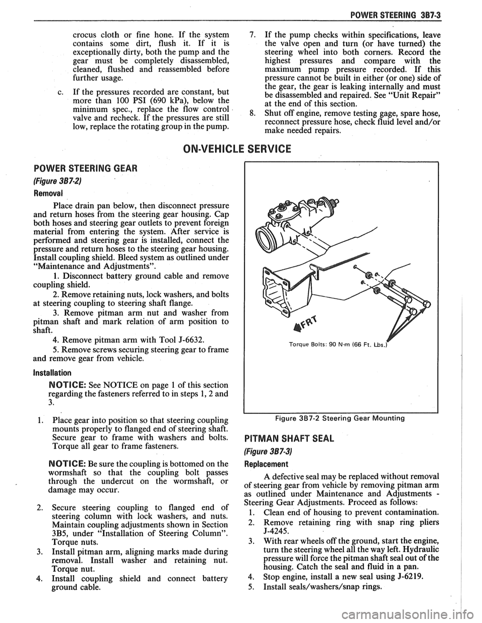
POWER STEERING GEAR
(Figure 387-2)
Removal
Place drain pan below, then disconnect pressure
and return hoses from the steering gear housing. Cap
both hoses and steering gear outlets to prevent foreign
material from entering the system. After service is
performed and steering gear is installed, connect the
pressure and return hoses to the steering gear housing.
Install coupling shield. Bleed system as outlined under
"Maintenance and Adjustments".
1. Disconnect battery ground cable and remove
coupling shield.
2. Remove retaining nuts, lock washers, and bolts
at steering coupling to steering shaft flange.
3. Remove pitman arm nut and washer from
pitman shaft and mark relation of arm position to
shaft.
4. Remove pitman arm with Tool J-6632.
5.
Remove screws securing steering gear to frame
and remove gear from vehicle.
Installation
NOTICE: See NOTICE on page 1 of this section
regarding the fasteners referred to in steps 1,2 and
3.
1. Place gear into position so that steering coupling
mounts properly to flanged end of steering shaft.
Secure gear to frame with washers and bolts.
Torque all gear to frame fasteners.
NOTICE: Be sure the coupling is bottomed on the
wormshaft so that the coupling bolt passes
through the undercut on the wormshaft, or
damage may occur.
2. Secure steering coupling to flanged end of
steering column with lock washers, and nuts.
Maintain coupling adjustments shown in Section
3B5, under "Installation of Steering Column".
Torque nuts.
3. Install pitman arm, aligning marks made during
removal. Install washer and retaining nut.
Torque nut.
4. Install coupling shield and connect battery
ground cable.
Torque Bolts: 90 Nm (66 Ft. ~bs.r
Figure 3B7-2 Steering Gear Mounting
PITMAN SHAFT SEAL
(Figure 387-3)
Replacement
A defective seal may be replaced without removal
of steering gear from vehicle by removing
pitman arm
as outlined under Maintenance and Adjustments
-
Steering Gear Adjustments. Proceed as follows:
1. Clean end of housing to prevent contamination.
2. Remove retaining
ring with snap ring pliers
J-4245.
3. With rear wheels off the ground, start the engine,
turn the steering wheel all the way left. Hydraulic
pressure will force the
pitman shaft seal out of the
housing. Catch the seal and fluid in a pan.
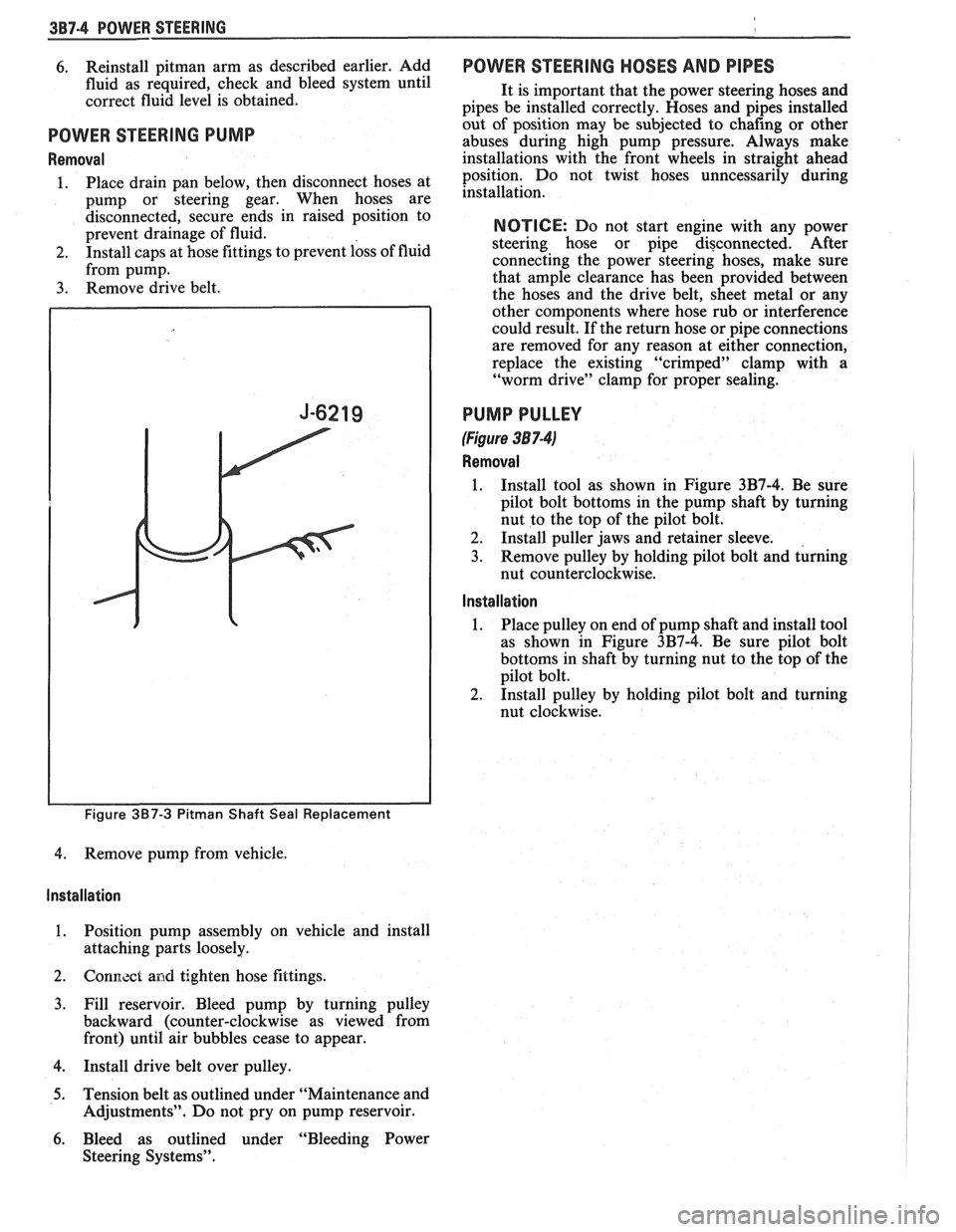
4. Stop engine, install a new seal using 5-6219.
5. Install seals/washers/snap rings.
Page 197 of 1825
3B7-4 POWER STEERING
6. Reinstall pitman arm as described earlier, Add
fluid as required, check and bleed system until
correct fluid level is obtained.
POWER STEERING PUMP
Removal
1. Place drain pan below, then disconnect hoses at
pump or steering gear. When hoses are
disconnected, secure ends in raised position to
prevent drainage of fluid.
2. Install caps at hose fittings to prevent loss of fluid
from pump.
3. Remove drive belt.
Figure 3B7-3 Pitman Shaft Seal Replacement
4. Remove pump from vehicle.
Installation
1. Position pump assembly on vehicle and install
attaching parts loosely.
2. Gonl7.zct and tighten hose fittings.
3. Fill reservoir. Bleed pump by turning pulley
backward (counter-clockwise as viewed from
front) until air bubbles cease to appear.
4. Install drive belt over pulley.
5. Tension belt as outlined under "Maintenance and
Adjustments". Do not pry on pump reservoir.
6. Bleed as outlined under "Bleeding Power
Steering Systems".
POWER STEERING HOSES AND PIPES
It is important that the power steering hoses and
pipes be installed correctly. Hoses and pipes installed
out of position may be subjected to chafing or other
abuses during high pump pressure. Always make
installations with the front wheels in straight ahead
position. Do not twist hoses unncessarily during
installation.
NOTICE: Do not start engine with any power
steering hose or pipe disconnected. After
connecting the power steering hoses, make sure
that ample clearance has been provided between
the hoses and the drive belt, sheet metal or any
other components where hose rub or interference
could result. If the return hose or pipe connections
are removed for any reason at either connection,
replace the existing "crimped" clamp with a
"worm drive" clamp for proper sealing.
PUMP PULLEY
(Figure 38 7-41
Removal
1. Install tool as shown in Figure 3B7-4. Be sure
pilot bolt bottoms in the pump shaft by turning
nut to the top of the pilot bolt.
2. Install puller jaws and retainer sleeve.
3. Remove pulley by holding pilot bolt and turning
nut counterclockwise.
Installation
1. Place
pulley on end of pump shaft and install tool
as shown in Figure 3B7-4. Be sure pilot bolt
bottoms in shaft by turning nut to the top of the
pilot bolt.
2. Install pulley by holding pilot bolt and turning
nut clockwise.
Page 203 of 1825
3B7-10 POWER STEERING
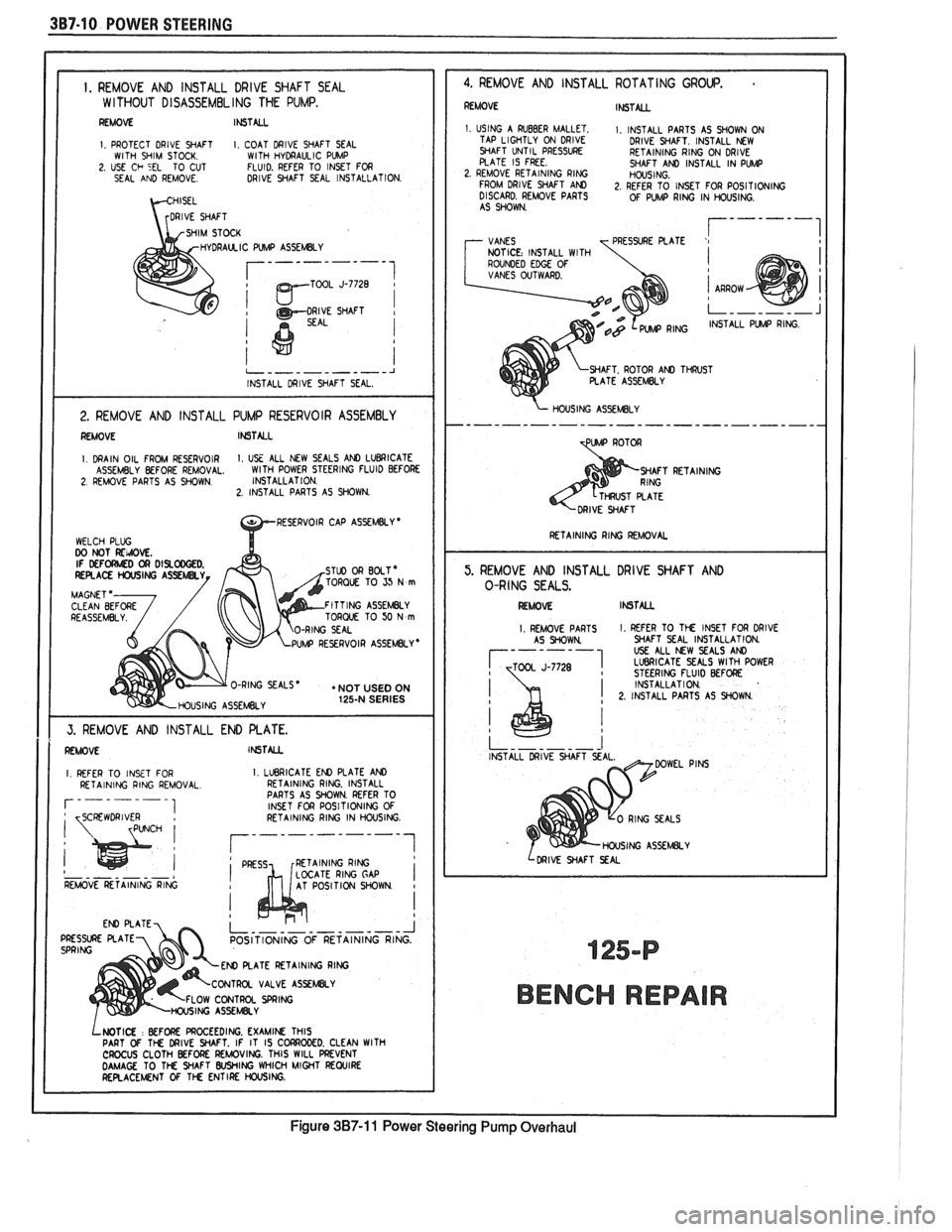
I. REMOVE AND INSTALL DRlVE SHAFT SEAL W l THOUT DISASSEMBL ING THE PUMP.
REMOVE It6TALL
I PROTECT DRlVE SHAFT I COAT DRIVE SHAFT SEAL WITH SHIM STOCK WITH HYDRAULIC PVMP 2 USE Ch 5EL TO CUT FLUID. REFER TO INSET FOR
SEAL AND REMOVE DRIVE SHAFT SEAL INSTALLATION
DRAUCIC WMP ASSEMBLY
TOOL J-7728
1
i
j
I
2. REMOVE AND INSTALL PUMP RESERVOIR ASSEMBLY I REMOVE INSTALL I I. DRAIN OIL FROM RESERVOIR I. USE ALL NEW SEALS AND LUBRICATE
ASSEMBLY BEFORE REMOVAL. WlTH
POWER STEERING FLUID BEFORE 2. REMOVE PARTS AS SHOWN. INSTALLAT
ION. 2. INSTALL PARTS AS SHOWN.
TORQUE TO SJ N m
FITTING ASSEMBLY
TORQUE TO 50 N m
UMP REYRVOIR ASSEMBLY *
O-RING SEALS * . NOT USED ON
HOUSING ASSEMBLY 125-N SERIES
1 1 I
REFER TO INSET FOR I. LLleRlCATE EN) PLATE AND I RETAINING RING. INSTALL
PARTS AS WOWN. REFER TO
INSET FOR POSITIONING
OF I
I RETAINING RING 1
- - - - - - - LOCATE RlNG GAP I REMOVE RETAINING RING AT POSITION WOWN I
POSITIONING OF RETAINING
ATE RETAINING RlNG
VALVE
ASSEWY
OW CONTROL SPRING
LWTI(X : BEFORE PROCEEDING. EXAMIN THIS
PART Of TM DRIVE WAFT. IF IT IS C CROCUS CLOTH BEFORE REMOVING. THIS WILL PREVENT DAMAGE TO TM WAFT WING WHICH MIGHT REWIRE RERACEMNT OF 1% ENTIRE HOUSING.
-- J RING.
4. REMOVE AND INSTALL ROTATING GROUP.
REMOVE INSTALL
1. USING A RUBBER MALLET. I. INSTALL PARTS AS SHOWN ON
TAP LIGHTLY ON DRIVE
DRIVE WAFT. INSTALL NEW
WAFT UNTIL
PRESSVRE RETAINING RING ON DRIVE
PLATE IS FREE. SHAFT AND INSTALL IN PW 2. REMOVE RETAINING RING HOUSING.
FROM DRlVE WAFT AM 2, REFER TO INSET FOR POSITIONING
DISCARD. REMOVE PARTS OF PUMP RING IN HOUSING.
AS SHOWN.
7 VANES r------I T PRESSURE PLATE '1 NOTICE: INSTALL WITH
ROUNDED EDGE OF VANES OVTWARD.
WAFT. ROTOR AN) TWST PLATE ASSEMBLY
PUIAP RING.
C
\- HOUSING ASSEMLY
TpW ROTOR
WAFT RETAINING
I RETAINING RlNG REMOVAL I
5. REMOVE AND INSTALL DRIVE SHAFT AND
O-RING SEALS.
I RLAOM INSTML
I. REMOVE PARTS 1. REFER TO TM INSET FOR DRlVE
AS WOWN WAFT SEAL INSTALLATION
USE ALL NW SEALS AND 1 LVBRlCATE SEALS WlTH POWER J-7728 STEERING FLUID BEFORE
INSTALLATION
! 2. INSTALL PARTS AS WOWN .
I
INSTALL DRIVE SHAFT
HOUSING ASSEMBLY
I LDRIVE WAFT SEAL
BENCH REPAIR
Figure 3B7-11 Power Steering Pump Overhaul
Page 208 of 1825
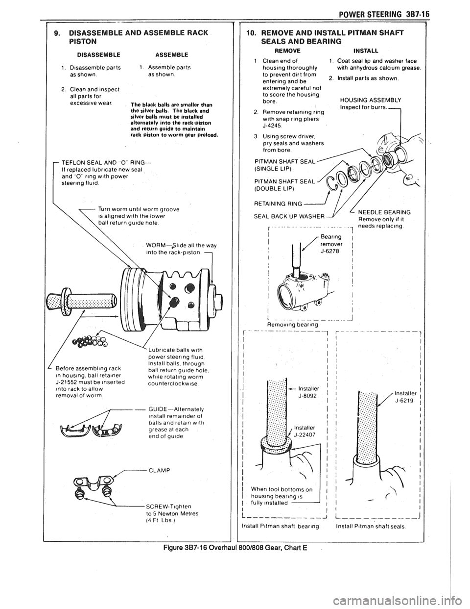
POWER STEERING 387-1 6
7 1 1 9. DISASSEMBLE AND ASSEMBLE RACK
1 PISTON
I DISASSEMBLE ASSEMBLE
1 Disassemble parts 1 Assemble parts
as shown as shown
2 Clean and Inspect all parts for excessive wear The black balls are smaller than
the silver balls. The black and
silver balls must
be installed
alternately into the rack-piston
and return guide to maintain
rack piston to worm gear
praloed.
TEFLON SEAL AN0 0 RING--
If replaced lubricate new seal
and 0 rlng wlth power steerlng fluid
Turn worm until worm groove IS al~gned w~th the lower
I \ WORM-Slide all the way
I \
Into the ra~k-~lston
1
v Lubr~cate balls wlth
I / oower steerlno fluid install balls th;ough Before assembling rack
ball return gulde hole In houslng. ball retalner whlle rotatlng worm J-21552 must be lnserted counterclockw~se Into rack to allow
removal of worm
- GUIDE-Alternately ~nstall rema~nder of
balls and retaln w~th grease at each
end of gu~de
to 5 Newton Metres (4 Ft Lbs )
10. REMOVE AND INSTALL PITMAN SHAR
SEALS AND BEARING
REMOVE INSTALL
1 Clean end of 1 Coat seal Ilp and washer face houslng thoroughly with anhydrous calclum grease
to prevent dlrt from enterlng and be 2. Install parts as shown
extremelv careful not
to score
(he houslng
bore HOUSING ASSEMBLY
Inspect for burrs
2 Remove retalnlng rlng wlth snap rlng pllers J-4245
3 Uslng screw drlver. pry seals and washers
from bore
PITMAN SHAFT SEAL
(SINGLE LIP)
PITMAN SHAFT SEAL
(DOUBLE LIP)
RETAINING
RING 2
SEAL BACK UP WASHER NEEDLE BEARING
Remove onlv 11 ~t I - - - - - .- - - - . - . - . -. . - - 1 needs replacing.
I
When tool bottoms on
fully Installed
I I
L ------------ J L ----------- J
Install Pltman shaft bearlng Install Pttman shaft seals
CI I J
Figure 387-16 Overhaul 800f808 Gear, Chart E
Page 1823 of 1825
8- CHASSIS INDEX
Recommended Fluids and Lubricants ................ OB-6
Relay Rod
......................................................... 3B6-2
Remote Mirror Control
...... See Body Service Section
5H.1. 15
Repair Procedures
.......................................... 88-50
S
........................................ Scheduled Maintenance OB- 1
Seats (Power) ....................................... Lumbar Support 8A- 145-0
............................. Sequential Fuel Injection 6E3-C2- 1
Service Engine Soon Light
.................................... 8C-3
Sheet Metal and Grille
................................ Section 2C
......................................... General Description .2 C. 1
........................................... Service Procedures .2 C. 1
................................................................. Hood .2 C. 1
...................................................... Hood Hinge 2C-2
Hood Latch and Cable
...................................... 2C-2
Paint
.............................................. Color Matching 2C-5
................................................ Identification -32-6
Interior Plastic Parts ...................................... 2C-6
................................................ Shock Absorbers 3D-
1
Shoe and Lining Assembly
. Brake
............................................ 3000/3 100 Series 5B1-3
3548 Series ...................................................... 5B6-4
Side Marker Lights
.............................................. 8B-2
........ Speakers See 8A- 150-0 & Body
Manual Section
6H- 1
.................... Spark Plug Gap .. .................. 6E3-13-3
................................ Speaker and Speaker Grille 9A-9
Special Tools
............................................ Air Conditioning 1 B-3 5
Air Conditioning Compressor
................................................. Overhaul 1D1-21
........................ Automatic Transaxle AT-700-R4-64
................................................................ Brakes SF-1
Clutch ................................................................ 7C-8
................................................................ Rear 4B1-20
....................................... Rear (Borg Warner) 4B-20
........................... Driveability and Emissions .6 E. 17
................................................ Engine Cooling 6B- 14
Power Steering Pump
& Gear ...................... 3B7-17
............................................... Propeller Shaft .4 A. 12
Steering Wheels and Columns
.......................... 5-35
Specifications Automatic Transmission Unit
............................................ Repair AT-700-R4-59
..................................................... Battery 6D 1-7
................................................................ Brakes 5F-1
Bumpers
......................................................... 2B-5
Charging System
................ .. ................... 6D3-3
.............................................................. Clutch .7 (2.8
....................................... Cranking System 6D2- 1 1
Driveability and Emissions ............................ 6E-23
................................................ Engine (V-6) ..6A 2.26
Engine (V-8) .................................................. 683-28
........................................ Front Suspension 3C- 10
Power Steering Gear and Pump
.................. 3B7-18 ............................................. Propeller Shaft .4 A. 12 ........................................................ Rear Axle 4B-19 ............................ Rear Axle (Borg Warner) 4B 1- 19
Rear Suspension
.............................................. 3D-9
.......................................... Replacement Bulbs 8Br 10 .............................................. Steering Linkage 3B6-6
Steering Wheels and Columns
...................... 3B5-35
........................................ Wheel Alignments 3A-4
....................................................... Speedometer 8C-2
........................................ Speedometer (Removal) 8C-5
...................................................... Speed Sensors 8C-1
Starter ........................................ Section 6D2. 8A-30-0
............................................. Starter (Circuit) 8A-30-0
Steering Linkage ...................................... Section 3B6
....................................... General Description 3B6-1
........................ Maintenance and Adjustments 3B6-1
................................................ On-Car Service 3B6-2
..................................................... Idler Arm 3B6-4
................................................ Pitman Arm 3B6-5
.................................................... Relay Rod 3B6-3
Tie Rods
...................................................... 3B6-2
.................................................. Specifications 3B6-6
Steering, Suspension, Tires and
Wheels Diagnosis
............................................................. 3-1
Steering Wheels and Columns
............................ 3B5-1
..................................... General Information 3B5- 1
Maintenance and Adjustments
...................... 3B5-'
On-Car Service .............................. .. ........... 3B5
Checking for Accident Damage
.................. 3B5-5
Intermediate Shaft ............... .. .................... 3B5-3
Park Lock Cable .......................................... 3B5-4
Standard Column
............................. Automatic Transaxle 3B5-13
Manual Transaxle ................................. 3B5- 19
Tilt Column
.............................. Automatic Transaxle 3B5-27
.................................. Manual Transaxle 3B5-19
Unit Repair Intermediate Shaft
...................................................... Assembly 3B5-6
................................................. Special Tools 3B5-35
Torque Specifications
.................................... 3B5-35
............................................. Starting System 8A-30-0
........................................ Strut Assembly (Front) 3C-4
.................................... ..... Symbols Chart ... 8A-3-0
T
.......................................................... Tachometer 9G-1
Tail/Stop/Turn Signal/Lights .......................... 8B-2
Temperature Cable
.............................................. 112 A-
Temperature Warning Light ................................ 8C-3
Theft Deterrent (Circuit)
.............................. 8A-133-0
Tie Rods
.............................................................. 3B6-2
Tires and Wheels
........................................ Section 3E
Diagnosis
.................................................. Section 3
General Information
......................................... 3E-1
................................................... Metric Tires 3E-2
....................................... Replacement Tires .31 E-
.................................................... Tire Placard 3E-2
........................................................... Wheels 3E-2
Maintenance and Adjustments
.......................... 3E-2
.......................... Aluminum Wheel Cleaning 3E-9
............................. ......... Inflation of Tires .. 3E-3
........................................ Tire Chain Usage 3E-4
.................................................. Tire Rotation 3E-3
.............................................. Wheel Repair 3E-2
...................................... Wheel Studs/Nuts 3E-3
........................................... Service Operations 3E-4
........................ Aluminum Wheel Cleaning 3E-9
.................................... Balance Precautions 3E-7
............................ Balancing Tire and Wheel 3E-7
.............................................. Compact Spare 3E-6
........................ Correcting Nonuniform Tires 3E-8