1988 OPEL VECTRA roof
[x] Cancel search: roofPage 2 of 525
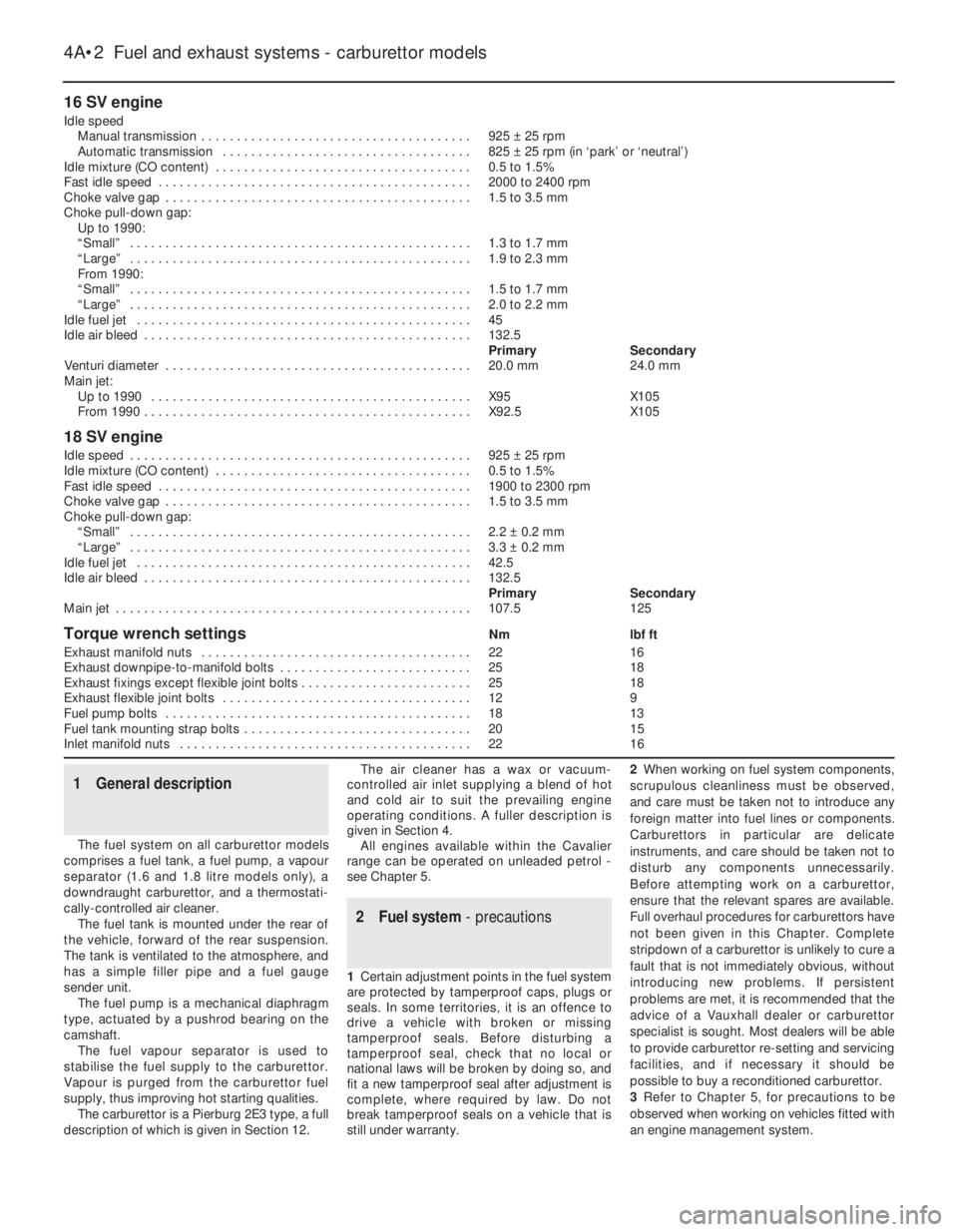
16 SV engine
Idle speed
Manual transmission . . . . . . . . . . . . . . . . . . . . . . . . . . . . . . . . . . . . . .925 ±25 rpm
Automatic transmission . . . . . . . . . . . . . . . . . . . . . . . . . . . . . . . . . . .825 ±25 rpm (in ‘park’ or ‘neutral’)
Idle mixture (CO content) . . . . . . . . . . . . . . . . . . . . . . . . . . . . . . . . . . . .0.5 to 1.5%
Fast idle speed . . . . . . . . . . . . . . . . . . . . . . . . . . . . . . . . . . . . . . . . . . . .2000 to 2400 rpm
Choke valve gap . . . . . . . . . . . . . . . . . . . . . . . . . . . . . . . . . . . . . . . . . . .1.5 to 3.5 mm
Choke pull-down gap:
Up to 1990:
“Small” . . . . . . . . . . . . . . . . . . . . . . . . . . . . . . . . . . . . . . . . . . . . . . . .1.3 to 1.7 mm
“Large” . . . . . . . . . . . . . . . . . . . . . . . . . . . . . . . . . . . . . . . . . . . . . . . .1.9 to 2.3 mm
From 1990:
“Small” . . . . . . . . . . . . . . . . . . . . . . . . . . . . . . . . . . . . . . . . . . . . . . . .1.5 to 1.7 mm
“Large” . . . . . . . . . . . . . . . . . . . . . . . . . . . . . . . . . . . . . . . . . . . . . . . .2.0 to 2.2 mm
Idle fuel jet . . . . . . . . . . . . . . . . . . . . . . . . . . . . . . . . . . . . . . . . . . . . . . .45
Idle air bleed . . . . . . . . . . . . . . . . . . . . . . . . . . . . . . . . . . . . . . . . . . . . . .132.5
PrimarySecondary
Venturi diameter . . . . . . . . . . . . . . . . . . . . . . . . . . . . . . . . . . . . . . . . . . .20.0 mm24.0 mm
Main jet:
Up to 1990 . . . . . . . . . . . . . . . . . . . . . . . . . . . . . . . . . . . . . . . . . . . . .X95X105
From 1990 . . . . . . . . . . . . . . . . . . . . . . . . . . . . . . . . . . . . . . . . . . . . . .X92.5X105
18 SV engine
Idle speed . . . . . . . . . . . . . . . . . . . . . . . . . . . . . . . . . . . . . . . . . . . . . . . .925 ±25 rpm
Idle mixture (CO content) . . . . . . . . . . . . . . . . . . . . . . . . . . . . . . . . . . . .0.5 to 1.5%
Fast idle speed . . . . . . . . . . . . . . . . . . . . . . . . . . . . . . . . . . . . . . . . . . . .1900 to 2300 rpm
Choke valve gap . . . . . . . . . . . . . . . . . . . . . . . . . . . . . . . . . . . . . . . . . . .1.5 to 3.5 mm
Choke pull-down gap:
“Small” . . . . . . . . . . . . . . . . . . . . . . . . . . . . . . . . . . . . . . . . . . . . . . . .2.2 ±0.2 mm
“Large” . . . . . . . . . . . . . . . . . . . . . . . . . . . . . . . . . . . . . . . . . . . . . . . .3.3 ±0.2 mm
Idle fuel jet . . . . . . . . . . . . . . . . . . . . . . . . . . . . . . . . . . . . . . . . . . . . . . .42.5
Idle air bleed . . . . . . . . . . . . . . . . . . . . . . . . . . . . . . . . . . . . . . . . . . . . . .132.5
PrimarySecondary
Main jet . . . . . . . . . . . . . . . . . . . . . . . . . . . . . . . . . . . . . . . . . . . . . . . . . .107.5125
Torque wrench settingsNmlbf ft
Exhaust manifold nuts . . . . . . . . . . . . . . . . . . . . . . . . . . . . . . . . . . . . . .2216
Exhaust downpipe-to-manifold bolts . . . . . . . . . . . . . . . . . . . . . . . . . . .2518
Exhaust fixings except flexible joint bolts . . . . . . . . . . . . . . . . . . . . . . . .2518
Exhaust flexible joint bolts . . . . . . . . . . . . . . . . . . . . . . . . . . . . . . . . . . .129
Fuel pump bolts . . . . . . . . . . . . . . . . . . . . . . . . . . . . . . . . . . . . . . . . . . .1813
Fuel tank mounting strap bolts . . . . . . . . . . . . . . . . . . . . . . . . . . . . . . . .2015
Inlet manifold nuts . . . . . . . . . . . . . . . . . . . . . . . . . . . . . . . . . . . . . . . . .2216
1General description
The fuel system on all carburettor models
comprises a fuel tank, a fuel pump, a vapour
separator (1.6 and 1.8 litre models only), a
downdraught carburettor, and a thermostati-
cally-controlled air cleaner.
The fuel tank is mounted under the rear of
the vehicle, forward of the rear suspension.
The tank is ventilated to the atmosphere, and
has a simple filler pipe and a fuel gauge
sender unit.
The fuel pump is a mechanical diaphragm
type, actuated by a pushrod bearing on the
camshaft.
The fuel vapour separator is used to
stabilise the fuel supply to the carburettor.
Vapour is purged from the carburettor fuel
supply, thus improving hot starting qualities.
The carburettor is a Pierburg 2E3 type, a full
description of which is given in Section 12.The air cleaner has a wax or vacuum-
controlled air inlet supplying a blend of hot
and cold air to suit the prevailing engine
operating conditions. A fuller description is
given in Section 4.
All engines available within the Cavalier
range can be operated on unleaded petrol -
see Chapter 5.
2Fuel system - precautions
1Certain adjustment points in the fuel system
are protected by tamperproof caps, plugs or
seals. In some territories, it is an offence to
drive a vehicle with broken or missing
tamperproof seals. Before disturbing a
tamperproof seal, check that no local or
national laws will be broken by doing so, and
fit a new tamperproof seal after adjustment is
complete, where required by law. Do not
break tamperproof seals on a vehicle that is
still under warranty.2When working on fuel system components,
scrupulous cleanliness must be observed,
and care must be taken not to introduce any
foreign matter into fuel lines or components.
Carburettors in particular are delicate
instruments, and care should be taken not to
disturb any components unnecessarily.
Before attempting work on a carburettor,
ensure that the relevant spares are available.
Full overhaul procedures for carburettors have
not been given in this Chapter. Complete
stripdown of a carburettor is unlikely to cure a
fault that is not immediately obvious, without
introducing new problems. If persistent
problems are met, it is recommended that the
advice of a Vauxhall dealer or carburettor
specialist is sought. Most dealers will be able
to provide carburettor re-setting and servicing
facilities, and if necessary it should be
possible to buy a reconditioned carburettor.
3Refer to Chapter 5, for precautions to be
observed when working on vehicles fitted with
an engine management system.
4A•2Fuel and exhaust systems - carburettor models
Page 7 of 525
13Clean any foreign matter from the float
chamber. Renew the float, the float needle
valve and seat if wear is evident, or if the float
is punctured or otherwise damaged. Check
that the needle valve closes completely before
the float reaches the top of its movement. See
Section 15, for details of float level checking.
14Renew the diaphragms in the part-load
enrichment valve and in the accelerator pump.
If additional pump or valve parts are supplied
in the overhaul kit, renew these parts also.
15Further dismantling is not recommended.
Pay particular attention to the throttle opening
mechanism arrangement if it is decided to
dismantle it; the interlocking arrangement is
important.
16Reassemble in the reverse order to
dismantling. Use new gaskets and seals
throughout; lubricate linkages with a smear of
molybdenum based grease.
Refitting
17Carry out the following procedure before
refitting.
a)Position the fast idle adjustment screw on
the highest step of the fast idle cam.
b)Use a gauge rod or twist drill of the
specified diameter to measure the
opening of the primary throttle valve.
c)Adjust if necessary at the fast idle
adjustment screw.
d)Note that this is a preliminary adjustment;
final adjustment of the fast idle speed
should take place with the engine running.
18Refitting is a reversal of removal, but
renew the gasket(s).
19After refitting, carry out the following
checks and adjustments.
20Check the throttle cable free play and
adjust if necessary, as described in Section 11.
21Check and if necessary top-up the
coolant level, as described in Chapter 3.
22Check and if necessary adjust the idle
speed and mixture, as described in Section 14.
14Idle speed and mixture -
adjustment
3
Note: Refer to Section 2 before proceeding.
To carry out the adjustments, an accurate
tachometer and an exhaust gas analyser (CO
meter) will be required
1To check the idle speed and mixture
adjustment, the following conditions must be
met:
a)The engine must be at normal operating
temperature
b)All electrical consumers (cooling fan,
heater blower, headlamps, etc.) must be
switched off
c)The ignition timing and spark plug gaps
must be correctly adjusted - see Chapters
1 and 5
d)The throttle cable free play must be
correctly adjusted - see Section 11
e)The air inlet trunking must be free from
leaks, and the air filter must be cleanf)On automatic models, always select
position, “P”.
2Connect a tachometer and an exhaust gas
analyser to the vehicle, according to the
equipment manufacturer’s instructions.
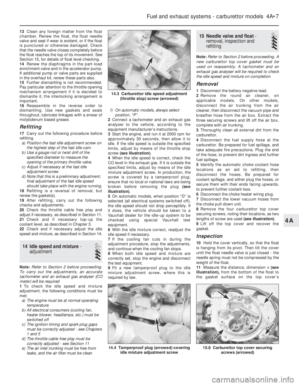
3Start the engine, and run it at 2000 rpm for
approximately 30 seconds, then allow it to
idle. If the idle speed is outside the specified
limits, adjust by means of the throttle stop
screw (see illustration).
4When the idle speed is correct, check the
CO level in the exhaust gas. If it is outside the
specified limits, adjust by means of the idle
mixture adjustment screw. In production, the
screw is covered by a tamperproof plug;
ensure that no local or national laws are being
broken before removing the plug (see
illustration).
5On automatic models, when position “D” is
selected (all electrical systems switched off),
the idle speed should not drop perceptibly. If
it does, the vehicle should be taken to a
Vauxhall dealer for the idle-up system to be
checked using special Vauxhall test
equipment.
6With the idle mixture correct, readjust the
idle speed if necessary.
7If the cooling fan cuts in during the
adjustment procedure, stop the adjustments,
and continue when the cooling fan stops.
8When both idle speed and mixture are
correctly set, stop the engine and disconnect
the test equipment.
9Fit a new tamperproof plug to the idle
mixture adjustment screw, where this is
required by law.
15Needle valve and float -
removal, inspection and
refitting
4
Note: Refer to Section 2 before proceeding. A
new carburettor top cover gasket must be
used on reassembly. A tachometer and an
exhaust gas analyser will be required to check
the idle speed and mixture on completion
Removal
1Disconnect the battery negative lead.
2Remove the round air cleaner, on
applicable models. On other models,
disconnect the air trunking from the air
cleaner, then disconnect the vacuum pipe and
breather hose from the air box. Extract the
three securing screws and lift off the air box,
complete with air trunking.
3Thoroughly clean all external dirt from the
carburettor.
4Disconnect the fuel supply hose at the
carburettor. Be prepared for fuel spillage, and
take adequate fire precautions. Plug the end
of the hose, to prevent dirt ingress and further
fuel spillage.
5Identify the automatic choke coolant hose
locations as an aid to refitting, then
disconnect the hoses. Be prepared for
coolant spillage, and either plug the hoses, or
secure them with their ends facing upwards,
to prevent further coolant loss.
6Disconnect the choke heater wiring plug.
7Disconnect the lower vacuum hoses from
the choke pull-down unit.
8Remove the four carburettor top cover
securing screws, noting their locations, as two
lengths of screw are used (see illustration).
9Lift off the top cover and recover the
gasket.
Inspection
10Hold the cover vertically, so that the float
is hanging from its pivot. Then tilt the cover
until the float needle valve is just closed - the
needle spring must not be compressed by the
weight of the float.
11Measure the distance, dimension x (see
illustration),from the bottom of the float to
the gasket surface on the top cover’s
Fuel and exhaust systems - carburettor models 4A•7
15.8 Carburettor top cover securing
screws (arrowed)14.4 Tamperproof plug (arrowed) covering
idle mixture adjustment screw
14.3 Carburettor idle speed adjustment
(throttle stop) screw (arrowed)
4A
Page 10 of 525
Fast idle cam position
20With the bi-metal housing removed, and
the choke valve gap “B”, correctly set,
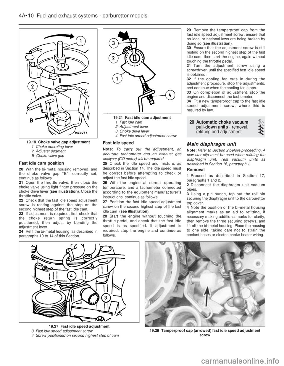
continue as follows.
21Open the throttle valve, then close the
choke valve using light finger pressure on the
choke drive lever (see illustration). Close the
throttle valve.
22Check that the fast idle speed adjustment
screw is resting against the stop on the
second highest step of the fast idle cam.
23If adjustment is required, first check that
the choke return spring is correctly
positioned, then adjust by bending the
adjustment lever.
24Refit the bi-metal housing, as described in
paragraphs 10 to 14 of this Section.
Fast idle speed
Note: To carry out the adjustment, an
accurate tachometer and an exhaust gas
analyser (CO meter) will be required
25Check the idle speed and mixture, as
described in Section 14. The idle speed must
be correct before attempting to check or
adjust the fast idle speed.
26With the engine at normal operating
temperature, and a tachometer connected
according to the equipment manufacturer’s
instructions, continue as follows.
27Position the fast idle speed adjustment
screw on the second highest step of the fast
idle cam (see illustration).
28Start the engine without touching the
throttle pedal, and check that the fast idle
speed is as specified. If adjustment is
required, stop the engine and continue as
follows.29Remove the tamperproof cap from the
fast idle speed adjustment screw, ensure that
no local or national laws are being broken by
doing so (see illustration).
30Ensure that the adjustment screw is still
resting on the second highest step of the fast
idle cam, then start the engine, again without
touching the throttle pedal.
31Turn the adjustment screw using a
screwdriver, until the specified fast idle speed
is obtained.
32If the cooling fan cuts in during the
adjustment procedure, stop the adjustments,
and continue when the cooling fan stops.
33On completion of adjustment, stop the
engine and disconnect the tachometer.
34Fit a new tamperproof cap to the fast idle
speed adjustment screw, where this is
required by law.
20Automatic choke vacuum
pull-down units - removal,
refitting and adjustment
3
Main diaphragm unit
Note: Refer to Section 2 before proceeding. A
new star clip must be used when refitting the
diaphragm unit. Test vacuum units as
described in Section 16, paragraph 1.
Removal
1Proceed as described in Section 17,
paragraphs 1 and 2.
2Disconnect the diaphragm unit vacuum
pipes.
3Using a pin punch, tap out the roll pin
securing the diaphragm unit to the carburettor
top cover.
4Note the position of the bi-metal housing
alignment marks as an aid to refitting, if
necessary making additional marks for clarity,
then remove the three securing screws, and
lift off the bi-metal housing. Place the housing
to one side, taking care not to strain the
coolant hoses or electric choke heater wiring.
4A•10Fuel and exhaust systems - carburettor models
19.18 Choke valve gap adjustment
1 Choke operating lever
2 Adjuster segment
B Choke valve gap
19.21 Fast idle cam adjustment
1 Fast idle cam
2 Adjustment lever
3 Choke drive lever
4 Fast idle speed adjustment screw
19.29 Tamperproof cap (arrowed) fast idle speed adjustment
screw19.27 Fast idle speed adjustment
3 Fast idle speed adjustment screw
4 Screw positioned on second highest step of cam
Page 15 of 525
12
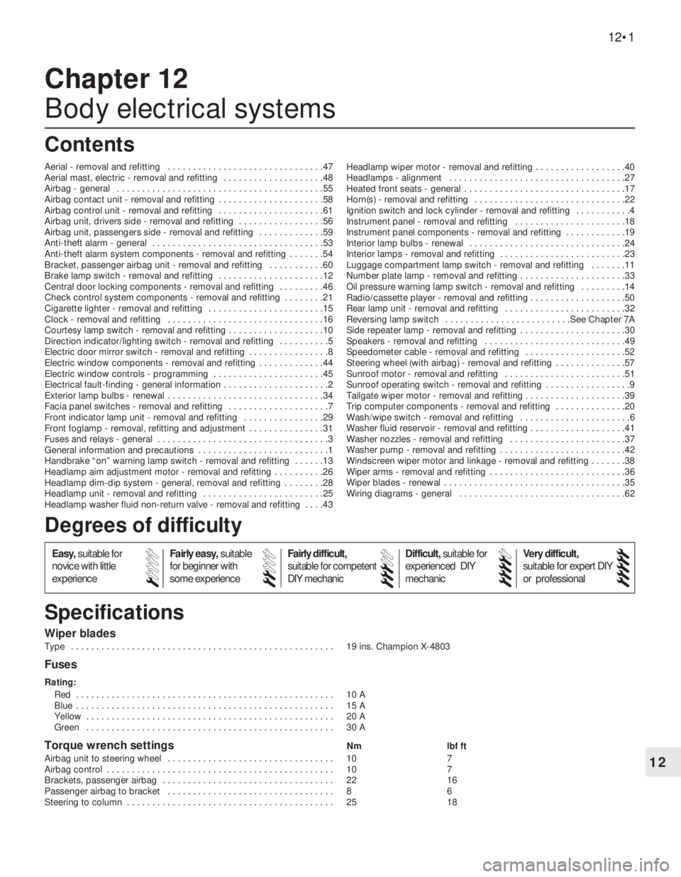
Wiper blades
Type . . . . . . . . . . . . . . . . . . . . . . . . . . . . . . . . . . . . . . . . . . . . . . . . . . . . 19 ins. Champion X-4803
Fuses
Rating:
Red . . . . . . . . . . . . . . . . . . . . . . . . . . . . . . . . . . . . . . . . . . . . . . . . . . . 10 A
Blue . . . . . . . . . . . . . . . . . . . . . . . . . . . . . . . . . . . . . . . . . . . . . . . . . . . 15 A
Yellow . . . . . . . . . . . . . . . . . . . . . . . . . . . . . . . . . . . . . . . . . . . . . . . . . 20 A
Green . . . . . . . . . . . . . . . . . . . . . . . . . . . . . . . . . . . . . . . . . . . . . . . . . 30 A
Torque wrench settingsNm lbf ft
Airbag unit to steering wheel . . . . . . . . . . . . . . . . . . . . . . . . . . . . . . . . . 10 7
Airbag control . . . . . . . . . . . . . . . . . . . . . . . . . . . . . . . . . . . . . . . . . . . . . 10 7
Brackets, passenger airbag . . . . . . . . . . . . . . . . . . . . . . . . . . . . . . . . . . 22 16
Passenger airbag to bracket . . . . . . . . . . . . . . . . . . . . . . . . . . . . . . . . . 8 6
Steering to column . . . . . . . . . . . . . . . . . . . . . . . . . . . . . . . . . . . . . . . . . 25 18
Chapter 12
Body electrical systems
Aerial - removal and refitting . . . . . . . . . . . . . . . . . . . . . . . . . . . . . . .47
Aerial mast, electric - removal and refitting . . . . . . . . . . . . . . . . . . . .48
Airbag - general . . . . . . . . . . . . . . . . . . . . . . . . . . . . . . . . . . . . . . . . .55
Airbag contact unit - removal and refitting . . . . . . . . . . . . . . . . . . . . .58
Airbag control unit - removal and refitting . . . . . . . . . . . . . . . . . . . . .61
Airbag unit, drivers side - removal and refitting . . . . . . . . . . . . . . . . .56
Airbag unit, passengers side - removal and refitting . . . . . . . . . . . . .59
Anti-theft alarm - general . . . . . . . . . . . . . . . . . . . . . . . . . . . . . . . . . .53
Anti-theft alarm system components - removal and refitting . . . . . . .54
Bracket, passenger airbag unit - removal and refitting . . . . . . . . . . .60
Brake lamp switch - removal and refitting . . . . . . . . . . . . . . . . . . . . .12
Central door locking components - removal and refitting . . . . . . . . .46
Check control system components - removal and refitting . . . . . . . .21
Cigarette lighter - removal and refitting . . . . . . . . . . . . . . . . . . . . . . .15
Clock - removal and refitting . . . . . . . . . . . . . . . . . . . . . . . . . . . . . . .16
Courtesy lamp switch - removal and refitting . . . . . . . . . . . . . . . . . . .10
Direction indicator/lighting switch - removal and refitting . . . . . . . . . .5
Electric door mirror switch - removal and refitting . . . . . . . . . . . . . . . .8
Electric window components - removal and refitting . . . . . . . . . . . . .44
Electric window controls - programming . . . . . . . . . . . . . . . . . . . . . .45
Electrical fault-finding - general information . . . . . . . . . . . . . . . . . . . . .2
Exterior lamp bulbs - renewal . . . . . . . . . . . . . . . . . . . . . . . . . . . . . . .34
Facia panel switches - removal and refitting . . . . . . . . . . . . . . . . . . . .7
Front indicator lamp unit - removal and refitting . . . . . . . . . . . . . . . .29
Front foglamp - removal, refitting and adjustment . . . . . . . . . . . . . . .31
Fuses and relays - general . . . . . . . . . . . . . . . . . . . . . . . . . . . . . . . . . .3
General information and precautions . . . . . . . . . . . . . . . . . . . . . . . . . .1
Handbrake “on” warning lamp switch - removal and refitting . . . . . .13
Headlamp aim adjustment motor - removal and refitting . . . . . . . . . .26
Headlamp dim-dip system - general, removal and refitting . . . . . . . .28
Headlamp unit - removal and refitting . . . . . . . . . . . . . . . . . . . . . . . .25
Headlamp washer fluid non-return valve - removal and refitting . . . .43Headlamp wiper motor - removal and refitting . . . . . . . . . . . . . . . . . .40
Headlamps - alignment . . . . . . . . . . . . . . . . . . . . . . . . . . . . . . . . . . .27
Heated front seats - general . . . . . . . . . . . . . . . . . . . . . . . . . . . . . . . .17
Horn(s) - removal and refitting . . . . . . . . . . . . . . . . . . . . . . . . . . . . . .22
Ignition switch and lock cylinder - removal and refitting . . . . . . . . . . .4
Instrument panel - removal and refitting . . . . . . . . . . . . . . . . . . . . . .18
Instrument panel components - removal and refitting . . . . . . . . . . . .19
Interior lamp bulbs - renewal . . . . . . . . . . . . . . . . . . . . . . . . . . . . . . .24
Interior lamps - removal and refitting . . . . . . . . . . . . . . . . . . . . . . . . .23
Luggage compartment lamp switch - removal and refitting . . . . . . .11
Number plate lamp - removal and refitting . . . . . . . . . . . . . . . . . . . . .33
Oil pressure warning lamp switch - removal and refitting . . . . . . . . .14
Radio/cassette player - removal and refitting . . . . . . . . . . . . . . . . . . .50
Rear lamp unit - removal and refitting . . . . . . . . . . . . . . . . . . . . . . . .32
Reversing lamp switch . . . . . . . . . . . . . . . . . . . . . . . . .See Chapter 7A
Side repeater lamp - removal and refitting . . . . . . . . . . . . . . . . . . . . .30
Speakers - removal and refitting . . . . . . . . . . . . . . . . . . . . . . . . . . . .49
Speedometer cable - removal and refitting . . . . . . . . . . . . . . . . . . . .52
Steering wheel (with airbag) - removal and refitting . . . . . . . . . . . . . .57
Sunroof motor - removal and refitting . . . . . . . . . . . . . . . . . . . . . . . .51
Sunroof operating switch - removal and refitting . . . . . . . . . . . . . . . . .9
Tailgate wiper motor - removal and refitting . . . . . . . . . . . . . . . . . . . .39
Trip computer components - removal and refitting . . . . . . . . . . . . . .20
Wash/wipe switch - removal and refitting . . . . . . . . . . . . . . . . . . . . . .6
Washer fluid reservoir - removal and refitting . . . . . . . . . . . . . . . . . . .41
Washer nozzles - removal and refitting . . . . . . . . . . . . . . . . . . . . . . .37
Washer pump - removal and refitting . . . . . . . . . . . . . . . . . . . . . . . . .42
Windscreen wiper motor and linkage - removal and refitting . . . . . . .38
Wiper arms - removal and refitting . . . . . . . . . . . . . . . . . . . . . . . . . . .36
Wiper blades - renewal . . . . . . . . . . . . . . . . . . . . . . . . . . . . . . . . . . . .35
Wiring diagrams - general . . . . . . . . . . . . . . . . . . . . . . . . . . . . . . . . .62
12•1
Specifications Contents
Easy,suitable for
novice with little
experienceFairly easy,suitable
for beginner with
some experienceFairly difficult,
suitable for competent
DIY mechanic
Difficult,suitable for
experienced DIY
mechanicVery difficult,
suitable for expert DIY
or professional
Degrees of difficulty
54321
Page 19 of 525
8Electric door mirror switch -
removal and refitting
2
Removal
1Disconnect the battery negative lead.
2Prise the plastic surround from the door
interior handle.
3Free the trim panel from the top edge of the
door by releasing the securing clips. This can
be done using a screwdriver, but it is
preferable to use a forked tool, to minimise
the possibility of damage to the trim panel and
the clips.
4Note the position of the mirror switch wiring
connector in the bracket at the top of the
door, then separate the two halves of the
connector.
5Prise the switch from the door trim panel,
and feed the wiring through the panel.
Refitting
6Refitting is a reversal of removal, but ensure
that the wiring is correctly routed, so as not to
foul the door interior handle mechanism.
9Sunroof operating switch -
removal and refitting
2
Removal
1Disconnect the battery negative lead.
2Prise the courtesy lamp from the roof trim
panel, and disconnect the wiring.
3Remove the two trim panel securing
screws, and withdraw the trim panel from the
roof, disconnecting the wiring from the
sunroof operating switch.
4Release the securing clips, then pull the
switch from the rear face of the trim panel.
Refitting
5Refitting is a reversal of removal.
10Courtesy lamp switch -
removal and refitting
2
Removal
1Disconnect the battery negative lead.
2Open the door and remove the switch
securing screw.
3Withdraw the switch from the door pillar,
and pull the wiring out sufficiently to prevent it
from springing back into the pillar.4Disconnect the wiring and remove the
switch.
Refitting
5Refitting is a reversal of removal.
11Luggage compartment lamp
switch - removal and refitting
2
Removal
1Disconnect the battery negative lead.
2Open the boot lid or tailgate, as applicable,
and remove the switch securing screw.
3Withdraw the switch from the body panel,
and pull the wiring out sufficiently to prevent it
from springing back into the body.
4Disconnect the wiring and remove the
switch.
Refitting
5Refitting is a reversal of removal.
12Brake lamp switch - removal
and refitting
2
Removal
1Disconnect the battery negative lead.
2Remove the lower trim panel from the
driver’s footwell.
3Disconnect the wiring plug from the brake
lamp switch, then twist the switch
anti-clockwise and remove it from its bracket.
Refitting
4Refitting is a reversal of removal.
13Handbrake “on” warning
lamp switch - removal and
refitting
3
For access to the switch, the handbrake
lever must be removed. Removal and refitting
of the switch is described as part of the
handbrake lever removal and refitting
procedure, in Chapter 9.
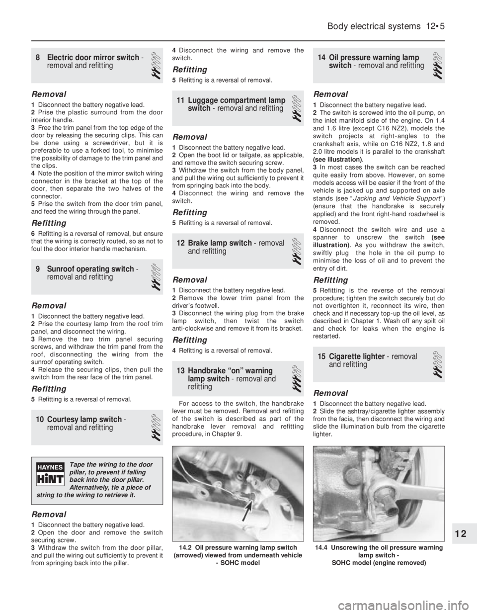
14Oil pressure warning lamp
switch - removal and refitting
3
Removal
1Disconnect the battery negative lead.
2The switch is screwed into the oil pump, on
the inlet manifold side of the engine. On 1.4
and 1.6 litre (except C16 NZ2), models the
switch projects at right-angles to the
crankshaft axis, while on C16 NZ2, 1.8 and
2.0 litre models it is parallel to the crankshaft
(see illustration).
3In most cases the switch can be reached
quite easily from above. However, on some
models access will be easier if the front of the
vehicle is jacked up and supported on axle
stands (see “Jacking and Vehicle Support”)
(ensure that the handbrake is securely
applied) and the front right-hand roadwheel is
removed.
4Disconnect the switch wire and use a
spanner to unscrew the switch (see
illustration). As you withdraw the switch,
swiftly plug the hole in the oil pump to
minimise the loss of oil and to prevent the
entry of dirt.
Refitting
5Refitting is the reverse of the removal
procedure; tighten the switch securely but do
not overtighten it, reconnect its wire, then
check and if necessary top-up the oil level, as
described in Chapter 1. Wash off any spilt oil
and check for leaks when the engine is
restarted.
15Cigarette lighter - removal
and refitting
2
Removal
1Disconnect the battery negative lead.
2Slide the ashtray/cigarette lighter assembly
from the facia, then disconnect the wiring and
slide the illumination bulb from the cigarette
lighter.
Body electrical systems 12•5
14.4 Unscrewing the oil pressure warning
lamp switch -
SOHC model (engine removed)14.2 Oil pressure warning lamp switch
(arrowed) viewed from underneath vehicle
- SOHC model
12
Tape the wiring to the door
pillar, to prevent if falling
back into the door pillar.
Alternatively, tie a piece of
string to the wiring to retrieve it.
Page 32 of 525
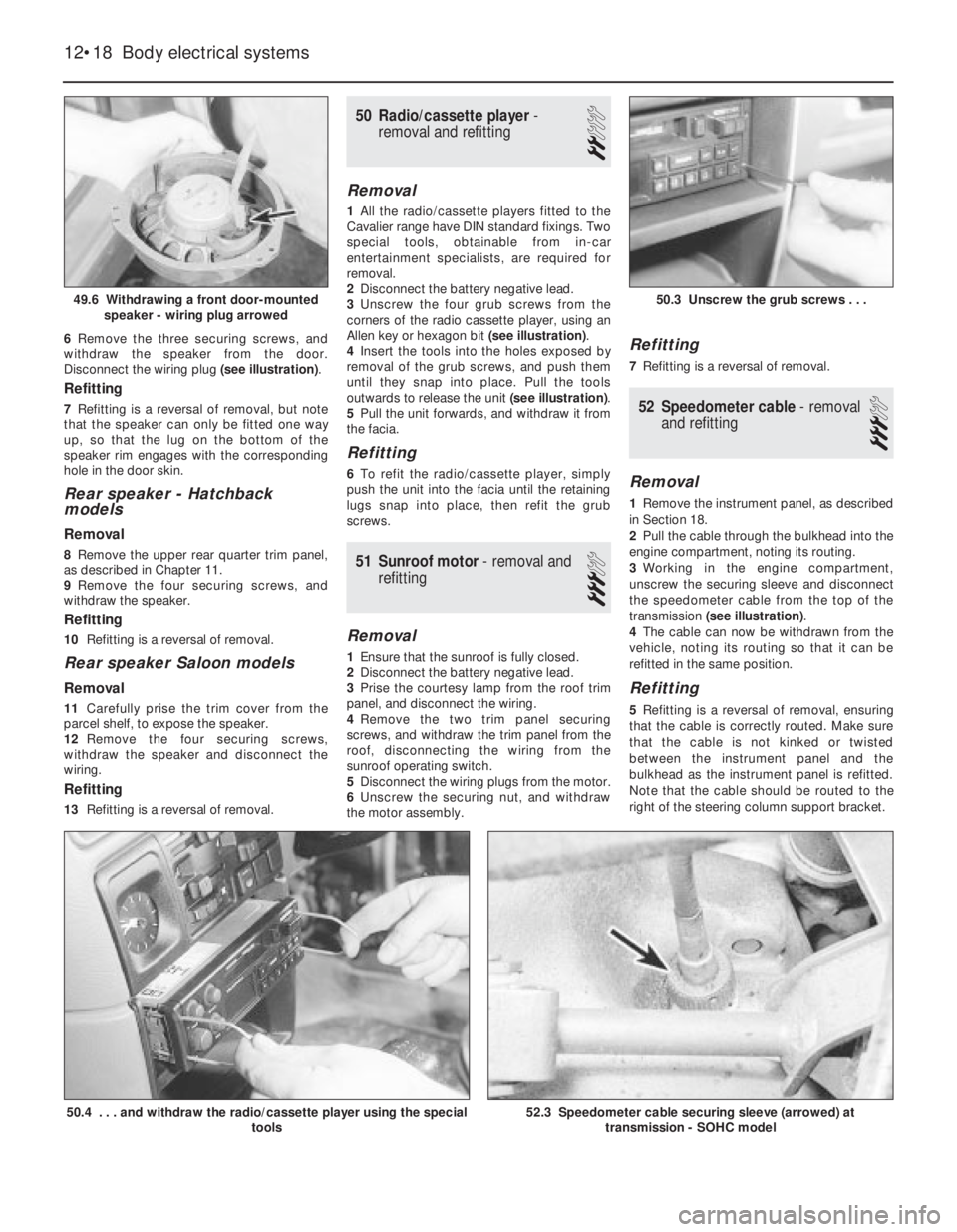
6Remove the three securing screws, and
withdraw the speaker from the door.
Disconnect the wiring plug (see illustration).
Refitting
7Refitting is a reversal of removal, but note
that the speaker can only be fitted one way
up, so that the lug on the bottom of the
speaker rim engages with the corresponding
hole in the door skin.
Rear speaker -Hatchback
models
Removal
8Remove the upper rear quarter trim panel,
as described in Chapter 11.
9Remove the four securing screws, and
withdraw the speaker.
Refitting
10Refitting is a reversal of removal.
Rear speaker Saloon models
Removal
11Carefully prise the trim cover from the
parcel shelf, to expose the speaker.
12Remove the four securing screws,
withdraw the speaker and disconnect the
wiring.
Refitting
13Refitting is a reversal of removal.
50Radio/cassette player -
removal and refitting
2
Removal
1All the radio/cassette players fitted to the
Cavalier range have DIN standard fixings. Two
special tools, obtainable from in-car
entertainment specialists, are required for
removal.
2Disconnect the battery negative lead.
3Unscrew the four grub screws from the
corners of the radio cassette player, using an
Allen key or hexagon bit (see illustration).
4Insert the tools into the holes exposed by
removal of the grub screws, and push them
until they snap into place. Pull the tools
outwards to release the unit (see illustration).
5Pull the unit forwards, and withdraw it from
the facia.
Refitting
6To refit the radio/cassette player, simply
push the unit into the facia until the retaining
lugs snap into place, then refit the grub
screws.
51Sunroof motor - removal and
refitting
3
Removal
1Ensure that the sunroof is fully closed.
2Disconnect the battery negative lead.
3Prise the courtesy lamp from the roof trim
panel, and disconnect the wiring.
4Remove the two trim panel securing
screws, and withdraw the trim panel from the
roof, disconnecting the wiring from the
sunroof operating switch.
5Disconnect the wiring plugs from the motor.
6Unscrew the securing nut, and withdraw
the motor assembly.
Refitting
7Refitting is a reversal of removal.
52Speedometer cable - removal
and refitting
3
Removal
1Remove the instrument panel, as described
in Section 18.
2Pull the cable through the bulkhead into the
engine compartment, noting its routing.
3Working in the engine compartment,
unscrew the securing sleeve and disconnect
the speedometer cable from the top of the
transmission (see illustration).
4The cable can now be withdrawn from the
vehicle, noting its routing so that it can be
refitted in the same position.
Refitting
5Refitting is a reversal of removal, ensuring
that the cable is correctly routed. Make sure
that the cable is not kinked or twisted
between the instrument panel and the
bulkhead as the instrument panel is refitted.
Note that the cable should be routed to the
right of the steering column support bracket.
12•18Body electrical systems
49.6 Withdrawing a front door-mounted
speaker - wiring plug arrowed
50.4 . . . and withdraw the radio/cassette player using the special
tools52.3 Speedometer cable securing sleeve (arrowed) at
transmission - SOHC model
50.3 Unscrew the grub screws . . .
Page 36 of 525
12•22Body electrical systems
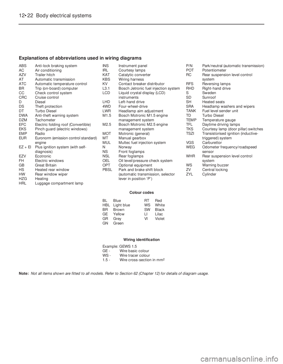
Explanations of abbreviations used in wiring diagrams
ABSAnti-lock braking system
ACAir conditioning
AZVTrailer hitch
ATAutomatic transmission
ATCAutomatic temperature control
BRTrip (on-board) computer
CCCheck control system
CRCCruise control
DDiesel
DSTheft protection
DTTurbo Diesel
DWAAnti-theft warning system
DZMTachometer
EFCElectric folding roof (Convertible)
EKSPinch guard (electric windows)
EMPRadio
EUREuronorm (emission control standard)
engine
EZ + ElPlus ignition system (with self-
diagnosis)
EZVEcotronic
FHElectric windows
GBGreat Britain
HSHeated rear window
HWRear window wiper
HZGHeating
HRLLuggage compartment lampINSInstrument panel
IRLCourtesy lamps
KATCatalytic converter
KBSWiring harness
KVContact breaker distributor
L3.1Bosch Jetronic fuel injection system
LCDLiquid crystal display (LCD)
instruments
LHDLeft-hand drive
4WDFour-wheel-drive
LWRHeadlamp aim adjustment
M1.5Bosch Motronic M1.5 engine
management system
M2.5Bosch Motronic M2.5 engine
management system
MOTMotronic (general)
MTManual gearbox
MULMultec fuel injection system
NNorway
NSFront foglamps
NSLRear foglamps
OELOil level/pressure check system
OPTOptional equipment
PBSLPark and brake shift block
(automatic transmission, selector
lever in position ‘P’)P/NPark/neutral (automatic transmission)
POTPotentiometer
RCRear suspension level control
system
RFSReversing lamps
RHDRight-hand drive
SSweden
SDSunroof
SHHeated seats
SRAHeadlamp washers and wipers
TANKFuel level sender unit
TDTurbo Diesel
TEMPTemperature gauge
TFLDaytime driving lamps
TKSCourtesy lamp (door pillar) switches
TSZITransistorised ignition (inductive-
triggered) system
VGSCarburettor
WEGOdometer frequency/roadspeed
sensor
WHRRear suspension level control
system
WSWarning buzzer
ZVCentral locking
ZYLCylinder
Colour codes
BLBlue
HBLLight blue
BRBrown
GEYellow
GRGrey
GNGreenRTRed
WSWhite
SWBlack
LILilac
VIViolet
Wiring identification
Example: GEWS 1.5
GE -Wire basic colour
WS -Wire tracer colour
1.5 -Wire cross-section in mm
2
Note: Not all items shown are fitted to all models. Refer to Section 62 (Chapter 12) for details of diagram usage.
Page 38 of 525
12•24Wiring diagrams
K84MSTS ignition control unit247 to 256
K85Automatic transmission control unit771 to 797
K86Check control unit370 to 392
K87Relay - auxiliary cooling fan833 to 834
K88Catalytic converter temperature control unit (not UK)760 to 762
K89Relay - rear fog lamps444 to 447
K90Relay - air conditioning compressor (not UK)820 to 821
K93Relay - air conditioning compressor (not UK)821 to 822
L1Ignition coil121 to 122, 133 to 134, 174 to 175,
225 to 226, 243 to 244, 261 to 262
M1Starter motor105 to 106
M2Windscreen wiper motor501 to 504
M4Cooling fan motor113
M6Headlamp wiper motor -left525 to 527
M7Headlamp wiper motor - right529 to 531
M8Rear window wiper motor513 to 515
M13Sunroof motor692 to 694
M18Central locking motor - driver’s door607 to 610
M19Central locking motor - left rear door622 to 624
M20Central locking motor - right rear door626 to 628
M21Fuel pump163, 196, 299
M26Electric aerial motor584 to 585
M30Door mirror motor and heater - driver’s door674 to 676
M31Door mirror motor and heater - passenger door680 to 682
M32Central locking motor - passengerdoor614to617
M33Idle speed adjuster146 to 149, 183 to 184, 277 to 278
M37Central locking motor - boot lid/tailgate618 to 621
M39Headlamp aim adjustment motor -left557 to 560
M40Headlamp aim adjustment motor - right561 to 564
M41Central locking motor - fuel filler flap623 to 625
M43Ride control actuator - front left (not UK)739 to 741
M44Ride control actuator - front right (not UK)743 to 745
M45Ride control actuator -rear left (not UK)747 to 749
M46Ride control actuator - rear right (not UK)751 to 753
M47Electric window motor - front left636 to 640
M48Electric window motor - front right654 to 658
M49Electric window motor - rear left642 to 646
M50Electric window motor - rear right660 to 664
M55Washer fluid pump518 to 519
P1Fuel gauge304
P2Coolant temperature gauge306
P3Clock551
P4Fuel level sender unit304
P5Coolant temperature sensor306
P7Tachometer308
P8Oil pressure gauge341
P9Voltmeter339
P10Oil pressure sensor341
P11Airflow meter (Motronic M4.1)185 to 189
P12Coolant temperature sensor178, 272
P13Trip computer outside air temperature sensor542 to 543
P14Distance sensor (not UK)336 to 337P17ABS wheel sensor - front left707
P18ABS wheel sensor -front right710
P19ABS wheel sensor -rear left712
P20ABS wheel sensor - rear right714
P21Speedometer frequency sensor (not UK)332
P23Pressure sensor 249 to 250
P24Oil temperature sensor251
P24Automatic transmission fluid temperature sensor795
P27Brake pad wear sensor - front left375
P28Brake pad wear sensor - front right375
P29Inlet manifold temperature sensor (not UK)207 to 208
P30Coolant temperature sensor209 to 210, 150
P31Throttle position sensor (not UK)209 to 211
P32Oxygen sensor - heated (not UK)193 to 194, 291 to 292
P33Oxygen sensor157
P34Throttle position sensor158 to 160, 780
P35Crankshaft speed/position sensor189 to 191, 223 to 225,
281 to 282
P39Trailer bulb failure sensor392 to 394
P43Electronic speedometer336
P44Air mass meter (Motronic M2.5)294 to 296
P45Automatic transmission input speed sensor787 to 788
P46Knock sensor284 to 285
P47Distributor ‘Hall-effect’ sensor (Motronic M2.5)287 to 288
P48Automatic transmission distance sensor785 to 786
P50Catalytic converter temperature sensor (not UK)761 to 762
R2Carburettor preheating116, 228
R3Cigarette lighter596 to 597
R5Glow plugs (Diesel models)858 to 859
R7Mixture preheating (not UK)232
R12Automatic choke117
R15Mixture adjustment potentiometer (not UK)155 to 157
R19Cooling fan motor resistor828, 848
S1Ignition switch102 to 106, 851 to 852
S2.1Lighting switch404 to 407
S2.2Courtesy lamp switch487
S2.3Instrument illumination lamp dimmer328
S3Heater blower switch837 to 844
S4Heated rear window switch570 to 571
S5.2Dipped beam switch438, 439
S5.3Direction indicator switch480 to 482
S5.4Sidelamp switch401 to 402
S7Reversing lamp switch497
S8Brake lamp switch462
S9.2Windscreen wiper switch501 to 504
S9.5Rear window wash/wiper switch516 to 518
S10Automatic transmission switch770 to 776
S11Brake fluid level warning sensor313
S13Handbrake-on warning switch315
S14Oil pressure switch310
S15Luggage compartment lamp switch485
S17Passenger door courtesy lamp switch490 Key to wiring diagrams for 1989 models (continued)
NoDescriptionTrackNoDescriptionTrack