1988 OPEL VECTRA height adjustment
[x] Cancel search: height adjustmentPage 162 of 525

4B
4Clamp the fuel hoses on either side of the
damper, to minimise fuel loss when the hoses
are disconnected.
5Loosen the clamp screws, and disconnect
the fuel hoses from the damper. Be prepared
for fuel spillage, and take adequate fire
precautions.
6Unscrew the securing nut, and withdraw
the damper from the bracket.
Refitting
7Refitting is a reversal of removal.
8Run the engine and check for leaks on
completion. If leakage is evident; stop the
engine immediately, and rectify the problem
without delay.
19Throttle cable - removal,
refitting and adjustment
3
Removal
1This procedure is basically the same as
described in Chapter 4A, but note the
following.
2Not all models are fitted with an air box.
Ignore references to it, if not applicable.
3For “carburettor” substitute “throttle body”,
and note that the cable bracket is bolted to
the inlet manifold.
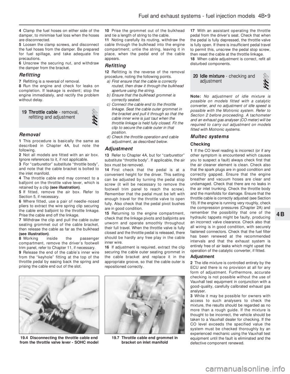
4The throttle cable end may connect to a
balljoint on the throttle valve lever, which is
retained by a clip (see illustration).
5If fitted, remove the air box. Refer to
Section 5, if necessary.
6Where fitted, use a pair of needle-nosed
pliers to extract the wire spring clip securing
the cable end balljoint to the throttle linkage.
Prise the cable end off the linkage.
7Withdraw the clip and pull the cable outer
seating grommet out of the cable bracket,
then release the cable as far as the bulkhead
(see illustration).
8Working inside the passenger
compartment, remove the driver’s footwell
trim panel, refer to Chapter 11, if necessary.
9Release the end of the cable’s inner wire
from the “keyhole” fitting at the top of the
throttle pedal by easing back the spring and
prising the cable end out of the slot.10Prise the grommet out of the bulkhead
and tie a length of string to the cable.
11Noting carefully its routing, withdraw the
cable through the bulkhead into the engine
compartment; untie the string, leaving it in
place, when the pedal end of the cable
appears.
Refitting
12Refitting is the reverse of the removal
procedure, noting the following points.
a)First ensure that the cable is correctly
routed, then draw it through the bulkhead
aperture using the string.
b)Ensure that the bulkhead grommet is
correctly seated.
c)Connect the cable end to the throttle
linkage. Seat the cable outer grommet in
the bracket and pull it through so that the
cable inner wire is just taut when the
throttle linkage is held fully closed. Fit the
clip to secure the cable outer in that
position.
d)Check the throttle operation and cable
adjustment, as described below.
Adjustment
13Refer to Chapter 4A, but for “carburettor”
substitute “throttle body”. If applicable, the air
box must be removed.
14First check that the pedal is at a
convenient height for the driver. This setting
can be adjusted by turning the pedal stop
screw (it will be necessary to remove the
footwell trim panel to reach the screw).
Remember that the pedal must be left with
enough travel for the throttle valve to open
fully. Also check that the pedal pivot bushes
are in good condition.
15Returning to the engine compartment,
check that the linkage pivots and balljoints are
unworn and operate smoothly throughout
their full travel. When the throttle valve is fully
closed and the throttle pedal is released, there
should be hardly any free play in the cable
inner wire.
16If adjustment is required, extract the clip
securing the cable outer seating grommet in
the cable bracket and replace it in the
appropriate groove, so that the cable outer is
repositioned correctly.17With an assistant operating the throttle
pedal from the driver’s seat. Check that when
the pedal is fully depressed, the throttle valve
is fully open. If there is insufficient pedal travel
to permit this, unscrew the pedal stop screw,
then reset the cable at the throttle linkage.
18When cable adjustment is correct, refit all
disturbed components.
20Idle mixture - checking and
adjustment
3
Note: No adjustment of idle mixture is
possible on models fitted with a catalytic
converter, and no adjustment of idle speed is
possible with the Motronic system. Refer to
Section 2 before proceeding. A tachometer
and an exhaust gas analyser (CO meter) will be
required to carry out adjustment on models
fitted with Motronic systems.
Multec systems
Checking
1If the CO level reading is incorrect (or if any
other symptom is encountered which causes
you to suspect a fault) always check first that
the air cleaner element is clean. Check also
that the spark plugs are in good condition and
correctly gapped. Ensure that the engine
breather and vacuum hoses are clear and
undamaged. Check that there are no leaks in
the air inlet trunking. Check the throttle body
and the manifolds for damage. Ensure that the
throttle cable is correctly adjusted (see Section
19). If the engine is running very roughly, check
the compression pressures (Chapter 2A) and
remember the possibility that one of the
hydraulic tappets might be faulty, producing
an incorrect valve clearance. Check also that
all wiring is in good condition, with securely
fastened connectors. Check that the fuel filter
has been renewed at the recommended
intervals and that the exhaust system is
entirely free of air leaks which might upset the
operation of the catalytic converter, if fitted.
Adjustment
2The idle mixture is controlled entirely by the
ECU and there is no provision at all for any
form of adjustment. Furthermore, accurate
checking is not possible without the use of
Vauxhall test equipment in conjunction with a
good-quality, carefully calibrated exhaust gas
analyser.
3While it may be possible for owners with
access to such analysers to check the
mixture, the results should be regarded as no
more than a rough guide. If the mixture is
thought to be incorrect, the vehicle should be
taken to a Vauxhall dealer for checking. If the
CO level exceeds the specified value the
system must be checked thoroughly by an
experienced mechanic using the Vauxhall test
equipment until the fault is eliminated and the
defective component renewed.
Fuel and exhaust systems - fuel injection models 4B•9
19.7 Throttle cable end grommet in
bracket on inlet manifold19.4 Disconnecting the throttle cable end
from the throttle valve lever - SOHC model
Page 175 of 525

1•4Maintenance schedule
Every 250 miles (400 km) or weekly
MRefer to “Weekly checks”
Basic service, every 9000 miles
(15 000 km) or 12 months -
whichever comes sooner
Along with the items in “Weekly checks”, carry out the
following:
MRenew the engine oil and oil filter (Section 3).
MCheck all hoses and other components for fluid
leaks (Section 4).
MCheck the steering and suspension components
(Section 5).
MCheck the condition of the driveshaft rubber
gaiters (Section 6).
MCheck the automatic transmission fluid level (if
applicable), (Section 7).
MCheck the radiator for blockage (e.g. dead insects)
and clean as necessary (Section 8).
MCheck and adjust the idle speed and mixture (if
applicable), (Section 9).
MCheck the throttle linkage and lubricate if
necessary (Section 10).
MCheck the exhaust system for corrosion, leaks and
security (Section 11).
MCheck all wiring for condition and security
(Section 12).
MCheck and adjust the ignition timing (if applicable),
(Section 13).
MRenew the brake fluid (Section 14).
MCheck the brake pad friction material for wear
(Section 15).
MCheck the handbrake linkage (Section 16).
MCheck the power steering fluid level (if applicable),
(Section 17).
MCheck the power steering pump drivebelt (if
applicable), (Section 18).
MCheck the rear suspension level control system
height, if fitted (Section 19).
MCheck the bodywork (Section 20).
MLubricate all locks and hinges (Section 21).
MCheck the alternator V-belt (Section 22).
MCheck the headlamp alignment (Section 23).
MReplace battery in the door-lock key (if applicable),
(Section 24).
MCarry out a road test (Section 25).
Note: Vauxhall specify that an Exhaust Emissions Test should be
carried out at least annually. However, this requires special
equipment, and is performed as part of the MOT test (refer to the
end of the manual).
Full service, every 18 000 miles
(30 000 km) or 24 months -
whichever comes sooner
Along with the ‘basic service’, carry out the following:
MRenew the coolant (Section 26).
MRenew the air cleaner element (Section 27).
MCheck the operation of the air cleaner air inlet
temperature control (carburettor models only),
(Section 28).
MRenew the fuel filter (Section 29).
MRenew the spark plugs (SOHC only), (Section 30) *.
MInspect and clean the distributor cap and HT leads
(Section 31).
MCheck the clutch cable adjustment (Section 32).
MCheck the manual transmission oil level (Section 33).
MCheck the automatic transmission (Section 34).
MCheck the brake drum shoe for wear (Section 35).
Major service, every 36 000 miles
(60 000 km) or 48 months -
whichever comes sooner
Along with the ‘full service’, carry out the following:
MRenew timing belt (Section 36).
MRenew the spark plugs (DOHC models only),
(Section 37).
MRenew automatic transmission fluid (Section 38) *.
* Note: If a vehicle is used for heavy-duty work (e.g. taxi work,
caravan/trailer towing, mostly short-distance, stop-start city driving)
the fluid must be changed every 36 months or 27 000 miles (45 000
km), whichever occurs first.
Page 188 of 525

2B
Note:All specifications as for 2.0 litre SOHC engines, unless shown otherwise
General
Type (all models) . . . . . . . . . . . . . . . . . . . . . . . . . . . . . . . . . . . . . . . . . . . Four-cylinder, in-line, water-cooled, transversely mounted. Double
belt-driven overhead camshafts, acting on hydraulic valve lifters
Manufacturer’s engine codes:
20 XEJ . . . . . . . . . . . . . . . . . . . . . . . . . . . . . . . . . . . . . . . . . . . . . . . . . 2.0 litre (1998 cc)
C20 XE . . . . . . . . . . . . . . . . . . . . . . . . . . . . . . . . . . . . . . . . . . . . . . . . 2.0 litre (1998 cc) + catalyst
X20 XEV . . . . . . . . . . . . . . . . . . . . . . . . . . . . . . . . . . . . . . . . . . . . . . . 2.0 litre (1998 cc) + catalyst. ‘Ecotec’ type engine
Compression ratio:
20 XEJ and C20 XE . . . . . . . . . . . . . . . . . . . . . . . . . . . . . . . . . . . . . . . 10.5 : 1
X20 XEV . . . . . . . . . . . . . . . . . . . . . . . . . . . . . . . . . . . . . . . . . . . . . . . 10.8 : 1
Maximum power:
20 XEJ and C20 XE . . . . . . . . . . . . . . . . . . . . . . . . . . . . . . . . . . . . . . . 110 kW (150 bhp) at 6000 rpm
X20 XEV . . . . . . . . . . . . . . . . . . . . . . . . . . . . . . . . . . . . . . . . . . . . . . . 100 kW (136 bhp) at 5400 rpm
Maximum torque:
20 XEJ . . . . . . . . . . . . . . . . . . . . . . . . . . . . . . . . . . . . . . . . . . . . . . . . . 196 Nm at 4800 rpm
C20 XE
Up to model year 1993 . . . . . . . . . . . . . . . . . . . . . . . . . . . . . . . . . . 196 Nm at 4800 rpm
1993-on . . . . . . . . . . . . . . . . . . . . . . . . . . . . . . . . . . . . . . . . . . . . . . 196 Nm at 4600 rpm
X20 XEV . . . . . . . . . . . . . . . . . . . . . . . . . . . . . . . . . . . . . . . . . . . . . . . 185 Nm at 4000 rpm
Cylinder Head
Overall height of cylinder head (sealing surface to sealing surface):
20 XEJ and C20 XE . . . . . . . . . . . . . . . . . . . . . . . . . . . . . . . . . . . . . . . 135.58 to 135.68 mm
X20 XEV . . . . . . . . . . . . . . . . . . . . . . . . . . . . . . . . . . . . . . . . . . . . . . . 134.00 mm
Installation height of valve guide:
20 XEJ and C20 XE . . . . . . . . . . . . . . . . . . . . . . . . . . . . . . . . . . . . . . . 10.70 to 11.00 mm
X20 XEV . . . . . . . . . . . . . . . . . . . . . . . . . . . . . . . . . . . . . . . . . . . . . . . 13.70 to 14.00 mm
Camshaft
Camshaft bearing journal diameter (all models) . . . . . . . . . . . . . . . . . . . 27.939 to 27.960 mm
Camshaft bearing diameter in housing (all models) . . . . . . . . . . . . . . . . 28.000 to 28.021 mm
Cam lift:
20 XEJ and C20 XE . . . . . . . . . . . . . . . . . . . . . . . . . . . . . . . . . . . . . . . 9.5 mm
X20 XEV . . . . . . . . . . . . . . . . . . . . . . . . . . . . . . . . . . . . . . . . . . . . . . . 10.0 mm
Maximum permissible radial run-out:
20 XEJ and C20 XE . . . . . . . . . . . . . . . . . . . . . . . . . . . . . . . . . . . . . . . 0.04 mm
X20 XEV . . . . . . . . . . . . . . . . . . . . . . . . . . . . . . . . . . . . . . . . . . . . . . . 0.06 mm
Endfloat (all models) . . . . . . . . . . . . . . . . . . . . . . . . . . . . . . . . . . . . . . . . 0.040 to 0.144 mm
Chapter 2 Part B:
DOHC engine procedures
Camshaft front oil seal - removal and refitting . . . . . . . . . . . . . . . . . . .6
Camshafts - removal, inspection and refitting . . . . . . . . . . . . . . . . . . .7
Crankshaft front oil seal - renewal . . . . . . . . . . . . . . . . . . . . . . . . . . .12
Cylinder head - dismantling and reassembly . . . . . . . . . . . . . . . . . . .10
Cylinder head - removal and refitting (engine in vehicle) . . . . . . . . . . .8
Cylinder head - removal and refitting (engine removed) . . . . . . . . . . . .9
Engine - removal and refitting . . . . . . . . . . . . . . . . . . . . . . . . . . . . . . .2
Engine/transmission mountings - renewal . . . . . . . . . . . . . . . . . . . . . .3
General . . . . . . . . . . . . . . . . . . . . . . . . . . . . . . . . . . . . . . . . . . . . . . . . .1Oil cooler - removal and refitting . . . . . . . . . . . . . . . . . . . . . . . . . . . .15
Oil pump - removal and refitting . . . . . . . . . . . . . . . . . . . . . . . . . . . . .14
Sump - removal and refitting . . . . . . . . . . . . . . . . . . . . . . . . . . . . . . .13
Timing belt, sprockets and belt tensioner and idler pulleys - removal,
refitting and adjustment . . . . . . . . . . . . . . . . . . . . . . . . . . . . . . . . . .4
Timing belt, with automatic adjuster - removal, refitting and
adjustment . . . . . . . . . . . . . . . . . . . . . . . . . . . . . . . . . . . . . . . . . . . .5
Valve lifters - general . . . . . . . . . . . . . . . . . . . . . . . . . . . . . . . . . . . . .11
2B•1
Specifications Contents
Easy,suitable for
novice with little
experienceFairly easy,suitable
for beginner with
some experienceFairly difficult,
suitable for competent
DIY mechanic
Difficult,suitable for
experienced DIY
mechanicVery difficult,
suitable for expert DIY
or professional
Degrees of difficulty
54321
Page 254 of 525

Excessive fuel consumption
MAir filter element dirty or clogged (Chapter 1).
MChoke cable incorrectly adjusted, or choke sticking - carburettor
models (Chapter 4A).
MFuel injection system fault - fuel-injected models (Chapter 4B).
MIgnition timing incorrect/ignition system fault (Chapters 1 and 5).
MTyres under-inflated (Chapter 1).
Fuel leakage and/or fuel odour
MDamaged or corroded fuel tank, pipes or connections (Chapter 4A
or 4B).
MCarburettor float chamber flooding (float height incorrect) -
carburettor models (Chapter 4A).
Excessive noise or fumes from exhaust system
MLeaking exhaust system or manifold joints (Chapters 1 and 4C).
MLeaking, corroded or damaged silencers or pipe (Chapters 1 and 4C).
MBroken mountings causing body or suspension contact (Chapter 1).
Pedal travels to floor - no pressure or very little
resistance
MBroken clutch cable (Chapter 6).
MIncorrect clutch cable adjustment (Chapter 6).
MBroken clutch release bearing or fork (Chapter 6).
MBroken diaphragm spring in clutch pressure plate (Chapter 6).
Clutch fails to disengage (unable to select gears).
MIncorrect clutch cable adjustment (Chapter 6).
MClutch disc sticking on transmission input shaft splines (Chapter 6).
MClutch disc sticking to flywheel or pressure plate (Chapter 6).
MFaulty pressure plate assembly (Chapter 6).
MClutch release mechanism worn or incorrectly assembled (Chapter 6).
Clutch slips (engine speed increases, with no
increase in vehicle speed).
MIncorrect clutch cable adjustment (Chapter 6).
MClutch disc linings excessively worn (Chapter 6).MClutch disc linings contaminated with oil or grease (Chapter 6).
MFaulty pressure plate or weak diaphragm spring (Chapter 6).
Judder as clutch is engaged
MClutch disc linings contaminated with oil or grease (Chapter 6).
MClutch disc linings excessively worn (Chapter 6).
MClutch cable sticking or frayed (Chapter 6).
MFaulty or distorted pressure plate or diaphragm spring (Chapter 6).
MWorn or loose engine or transmission mountings (Chapter 2A or 2B).
MClutch disc hub or transmission input shaft splines worn (Chapter 6).
Noise when depressing or releasing clutch pedal
MWorn clutch release bearing (Chapter 6).
MWorn or dry clutch pedal bushes (Chapter 6).
MFaulty pressure plate assembly (Chapter 6).
MPressure plate diaphragm spring broken (Chapter 6).
MBroken clutch disc cushioning springs (Chapter 6).
Fault Finding REF•15
REF
Overheating
MInsufficient coolant in system (Chapter 1).
MThermostat faulty (Chapter 3).
MRadiator core blocked, or grille restricted (Chapter 3).
MElectric cooling fan or thermoswitch faulty (Chapter 3).
MPressure cap faulty (Chapter 3).
MIgnition timing incorrect/ignition system fault (Chapters 1 and 5).
MInaccurate temperature gauge sender unit (Chapter 3).
MAirlock in cooling system (Chapter 1).
Overcooling
MThermostat faulty (Chapter 3).
MInaccurate temperature gauge sender unit (Chapter 3).
External coolant leakage
MDeteriorated or damaged hoses or hose clips (Chapter 1).
MRadiator core or heater matrix leaking (Chapter 3).
MPressure cap faulty (Chapter 3).
MWater pump seal leaking (Chapter 3).
MBoiling due to overheating (Chapter 3).
MCore plug leaking (Chapter 2A).
Internal coolant leakage
MLeaking cylinder head gasket (Chapter 2A or 2B).
MCracked cylinder head or cylinder bore (Chapter 2A or 2B).
Corrosion
MInfrequent draining and flushing (Chapter 1).
MIncorrect coolant mixture or inappropriate coolant type (Chapter 1).
Cooling system
Clutch
Fuel and exhaust systems