1988 OPEL VECTRA transmission
[x] Cancel search: transmissionPage 223 of 525
25Flywheel -removal, inspection
and refitting
4
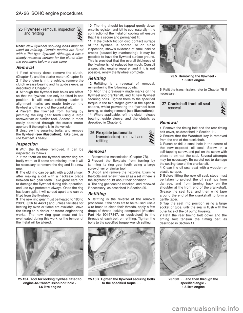
Note: New flywheel securing bolts must he
used on refitting. Certain models are fitted
with a ‘Pot type’ flywheel. Although, it has a
deeply recessed surface for the clutch disc,
the operations below are the same.
Removal
1If not already done, remove the clutch,
(Chapter 6), and the starter motor, (Chapter 5).
2If the engine is in the vehicle, remove the
clutch release bearing and its guide sleeve, as
described in Chapter 6.
3Although the flywheel bolt holes are offset
so that the flywheel can only be fitted in one
position, it will make refitting easier if
alignment marks are made between the
flywheel and the end of the crankshaft.
4Prevent the flywheel from turning by
jamming the ring gear teeth using a large
screwdriver or similar tool. Access is most
easily obtained through the starter motor
aperture if the engine is in the vehicle.
5Unscrew the securing bolts, and remove
the flywheel (see illustration). Take care, as
the flywheel is heavy!
Inspection
6With the flywheel removed, it can be
inspected as follows.
7If the teeth on the flywheel starter ring are
badly worn, or if some are missing, then it will
be necessary to remove the ring and fit a new
one.
8The old ring can be split with a cold chisel,
after making a cut with a hacksaw blade
between two gear teeth. Take great care not
to damage the flywheel during this operation,
and use eye protectors always. Once the ring
has been split, it will spread apart and can be
lifted from the flywheel.
9The new ring gear must be heated to 180 to
230°C (356 to 446°F) and unless facilities for
heating by oven or flame are available, leave
the fitting to a dealer or motor engineering
works. The new ring gear must not be
overheated during this work, or the temper of
the metal will be altered.10The ring should be tapped gently down
onto its register, and left to cool naturally -the
contraction of the metal on cooling will ensure
that it is a secure and permanent fit.
11If the clutch friction disc contact surface
of the flywheel is scored, or on close
inspection, show’s evidence of small hairline
cracks (caused by overheating), it may be
possible to have the flywheel surface ground.
This is provided that the overall thickness of
the flywheel is not reduced too much. Consult
a specialist engine repairer and if it is not
possible, renew the flywheel complete.
Refitting
12Refitting is a reversal of removal,
remembering the following points.
13Align the previously made marks on the
flywheel and crankshaft, and fit new flywheel
securing bolts. Tighten them to the specified
torque in the two stages given in the Specifi-
cations, whilst preventing the flywheel from
turning, as during removal (see illustrations).
14Where applicable, refit the clutch release
bearing, guide sleeve, and the clutch, as
described in Chapter 6.
26Flexplate (automatic
transmission) -removal and
refitting
4
Removal
1Remove the transmission (Chapter 7B).
2Prevent the flexplate from turning by
jamming its ring gear teeth using a large
screwdriver or similar tool.
3Unbolt and remove the flexplate. Examine
the bolts and renew them all as a set if there is
the slightest doubt about their condition.
4The ring gear can be checked, and renewed
if necessary, as described in Section 25.
Refitting
5Refitting is the reverse of the removal
procedure. If the bolts are to be re-used, use a
wire brush to clean their threads, apply a few
drops of thread-locking compound (Vauxhall
Part No 90167347, or equivalent) to the
threads of each bolt on refitting. Tighten the
bolts to the specified torque wrench setting.6Refit the transmission, refer to Chapter 7B if
necessary.
27Crankshaft front oil seal -
renewal
3
Renewal
1Remove the timing belt and the rear timing
belt cover, as described in Section 11.
2Ensure that the Woodruff key is removed
from the end of the crankshaft.
3Punch or drill a small hole in the centre of
the now-exposed oil seal. Screw in a
self-tapping screw, and pull on the screw with
pliers to extract the seal. Several attempts
may be necessary. Be careful not to damage
the sealing face of the crankshaft.
4Clean the oil seal seat with a wooden or
plastic scraper.
5Before fitting the new oil seal, steps must
be taken to protect the oil seal lips from
damage, and from turning back on the
shoulder at the front end of the crankshaft.
Grease the seal lips, and then wind tape
around the end of the crankshaft to form a
gentle taper.
6Tap the seal into position using a large
socket or tube, until the seal is flush with the
outer face of the oil pump housing.
7Refit the rear timing belt cover and the
timing belt tension the timing belt as
described in Section 11.
2A•26SOHC engine procedures
25.13C . . .and then through the
specified angle -
1.6 litre engine25.13B Tighten the flywheel securing bolts
to the specified toque . . .25.13A Tool for locking flywheel fitted to
engine-to-transmission bolt hole -
1.6 litre engine
25.5 Removing the flywheel -
1.6 litre engine
Page 224 of 525
28Crankshaft rear oil seal -
renewal
4
Renewal
1With the engine removed from the vehicle,
remove the flywheel, or flexplate (as
applicable) as described in Sections 25 and
26.
2Punch or drill a small hole in the centre of
the now-exposed oil seal. Screw in a
self-tapping screw, and pull on the screw with
pliers to extract the seal. Several attempts
may be necessary. Be careful not to damage
the sealing face of the crankshaft.
3Clean the oil seal seat with a wooden or
plastic scraper.4Grease the lips of the new seal, then tap the
seal into position using a tube, until flush with
the outer faces of the cylinder block and rear
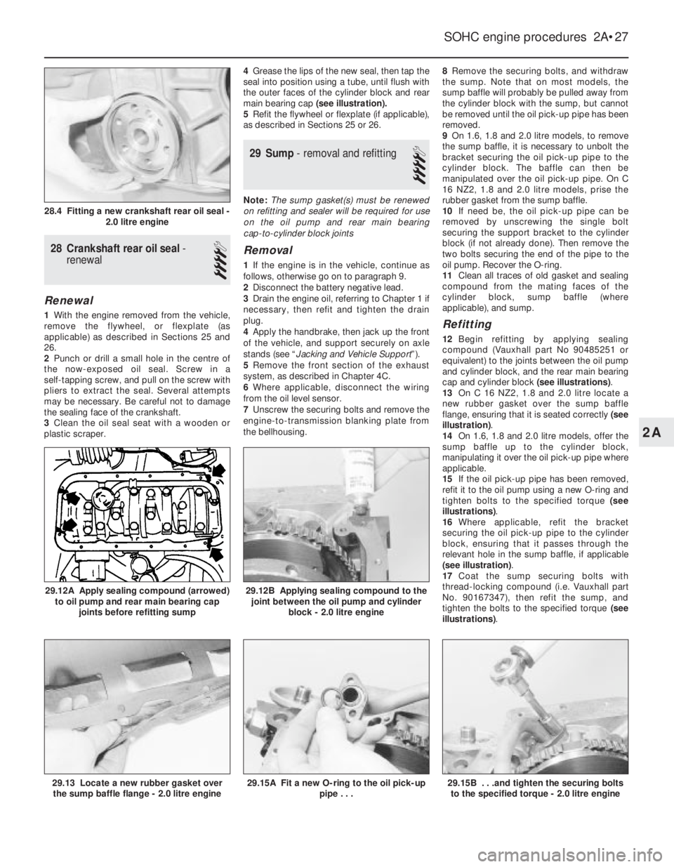
main bearing cap (see illustration).
5Refit the flywheel or flexplate (if applicable),
as described in Sections 25 or 26.
29Sump - removal and refitting
4
Note: The sump gasket(s) must be renewed
on refitting and sealer will be required for use
on the oil pump and rear main bearing
cap-to-cylinder block joints
Removal
1If the engine is in the vehicle, continue as
follows, otherwise go on to paragraph 9.
2Disconnect the battery negative lead.
3Drain the engine oil, referring to Chapter 1 if
necessary, then refit and tighten the drain
plug.
4Apply the handbrake, then jack up the front
of the vehicle, and support securely on axle
stands (see “Jacking and Vehicle Support”).
5Remove the front section of the exhaust
system, as described in Chapter 4C.
6Where applicable, disconnect the wiring
from the oil level sensor.
7Unscrew the securing bolts and remove the
engine-to-transmission blanking plate from
the bellhousing.8Remove the securing bolts, and withdraw
the sump. Note that on most models, the
sump baffle will probably be pulled away from
the cylinder block with the sump, but cannot
be removed until the oil pick-up pipe has been
removed.
9On 1.6, 1.8 and 2.0 litre models, to remove
the sump baffle, it is necessary to unbolt the
bracket securing the oil pick-up pipe to the
cylinder block. The baffle can then be
manipulated over the oil pick-up pipe. On C
16 NZ2, 1.8 and 2.0 litre models, prise the
rubber gasket from the sump baffle.
10If need be, the oil pick-up pipe can be
removed by unscrewing the single bolt
securing the support bracket to the cylinder
block (if not already done). Then remove the
two bolts securing the end of the pipe to the
oil pump. Recover the O-ring.
11Clean all traces of old gasket and sealing
compound from the mating faces of the
cylinder block, sump baffle (where
applicable), and sump.
Refitting
12Begin refitting by applying sealing
compound (Vauxhall part No 90485251 or
equivalent) to the joints between the oil pump
and cylinder block, and the rear main bearing
cap and cylinder block (see illustrations).
13On C 16 NZ2, 1.8 and 2.0 litre locate a
new rubber gasket over the sump baffle
flange, ensuring that it is seated correctly (see
illustration).
14On 1.6, 1.8 and 2.0 litre models, offer the
sump baffle up to the cylinder block,
manipulating it over the oil pick-up pipe where
applicable.
15If the oil pick-up pipe has been removed,
refit it to the oil pump using a new O-ring and
tighten bolts to the specified torque (see
illustrations).
16Where applicable, refit the bracket
securing the oil pick-up pipe to the cylinder
block, ensuring that it passes through the
relevant hole in the sump baffle, if applicable
(see illustration).
17Coat the sump securing bolts with
thread-locking compound (i.e. Vauxhall part
No. 90167347), then refit the sump, and
tighten the bolts to the specified torque (see
illustrations).
SOHC engine procedures 2A•27
29.12B Applying sealing compound to the
joint between the oil pump and cylinder
block - 2.0 litre engine
29.15B . . .and tighten the securing bolts
to the specified torque - 2.0 litre engine29.15A Fit a new O-ring to the oil pick-up
pipe . . .29.13 Locate a new rubber gasket over
the sump baffle flange - 2.0 litre engine
29.12A Apply sealing compound (arrowed)
to oil pump and rear main bearing cap
joints before refitting sump
28.4 Fitting a new crankshaft rear oil seal -
2.0 litre engine
2A
Page 231 of 525
5Note that the rubber plug located next to
the bellhousing flange on the cylinder block
covers the aperture for the installation of a
diagnostic TDC sensor. The sensor, when
connected to a monitoring unit, indicates TDC
from the position of the pins set into the
crankshaft balance weight.
37Examination and renovation
-general
4
General
1With the engine completely stripped, clean all
components and examine them for wear. Each
component should be checked, and where
necessary renewed or renovated, as described
in the relevant Sections of this Chapter.
2Renew main and big-end bearing shells as
a matter of course, unless it is known that
they have had little wear, and are in perfect
condition.
3If in doubt whether to renew a component
that is still just serviceable, consider the time
and effort that will be incurred should the
component fail at an early date after rebuild.
Obviously, the age and expected life of the
vehicle must influence the standards applied.4Gaskets, oil seals and O-rings must all be
renewed as a matter of routine. Flywheel,
cylinder head, and main and big-end bearing
cap bolts must be renewed, because of the
high stress to which they are subjected.
5Renew the engine core plugs while they are
easily accessible, if they show signs of
leakage. Knock out the old plugs with a
hammer and chisel or punch. Clean the plug
seats, smear the new plugs with sealing
compound, and tap them squarely into
position.
38Initial start-up after major
overhaul or repair
2
1Make a final check to ensure that
everything has been reconnected to the
engine, and that no rags or tools have been
left in the engine compartment.
2Check that oil and coolant levels are
correct.
3Start the engine. This may take a little longer
than usual, as fuel is pumped to the engine.
4Check that the oil pressure warning lamp
goes out when the engine starts. This may
take a few seconds as the new oil filter fills
with oil.5Run the engine at a fast tickover, and check
for leaks of oil, fuel and coolant. If a new
camshaft has been fitted, pay careful
attention to the running-in procedure given in
Section 18, paragraphs 17 and 18. Where
applicable, check the power steering and/or
automatic transmission fluid cooler unions for
leakage. Some smoke and odd smells may be
experienced, as assembly lubricants and
sealers burn off the various components.
6Bring the engine to normal operating
temperature. Check the ignition timing, idle
speed and the mixture (where applicable), as
described in Chapter 4A or 4B.
7Allow the engine to cool, then recheck the
oil and coolant levels. Top-up if necessary
8If new bearings, pistons, etc., have been
fitted, the engine should be run-in at reduced
speeds and loads for the first 500 miles (800
km) or so. It is beneficial to change the engine
oil and filter after this mileage.
2A•34SOHC engine procedures
Page 232 of 525
3
System type . . . . . . . . . . . . . . . . . . . . . . . . . . . . . . . . . . . . . . . . . . . Pressurised, with remote expansion tank. Coolant pump driven by
timing belt
Coolant
Type/specification (all models) . . . . . . . . . . . . . . . . . . . . . . . . . . . . . . . . See Lubricants and fluidsin “Weekly checks”
Capacity . . . . . . . . . . . . . . . . . . . . . . . . . . . . . . . . . . . . . . . . . . . . . . . . . See Chapter 1 Specifications
Thermostat
Starts to open at (all models) . . . . . . . . . . . . . . . . . . . . . . . . . . . . . . . . . 92°C
Fully open at (all models) . . . . . . . . . . . . . . . . . . . . . . . . . . . . . . . . . . . . 107°C
Operating temperature (approx.) . . . . . . . . . . . . . . . . . . . . . . . . . . . . . . 80°C
Expansion tank cap
Opening pressure (all models) . . . . . . . . . . . . . . . . . . . . . . . . . . . . . . . . 1.20 to 1.35 bar
Boiling point . . . . . . . . . . . . . . . . . . . . . . . . . . . . . . . . . . . . . . . . . . . . . . 125°C
Cooling fan switch
Switches on at (all models) . . . . . . . . . . . . . . . . . . . . . . . . . . . . . . . . . . . 100°C
Switches off at (all models) . . . . . . . . . . . . . . . . . . . . . . . . . . . . . . . . . . . 95°C
Torque wrench settingsNm lbf ft
Coolant pump bolts:
1.4 and 1.6 litre models
(except C16 NZ2), (M6) . . . . . . . . . . . . . . . . . . . . . . . . . . . . . . . . . . 8 6
C16 NZ2, 1.8 and 2.0 litre models (M8) . . . . . . . . . . . . . . . . . . . . . . . 25 18
Oil pipes to radiator . . . . . . . . . . . . . . . . . . . . . . . . . . . . . . . . . . . . . . . . 22 16
Outlet to thermostat housing,
C16 NZ2, 1.8 and 2.0 litre models . . . . . . . . . . . . . . . . . . . . . . . . . . . 8 6
Temperature sender . . . . . . . . . . . . . . . . . . . . . . . . . . . . . . . . . . . . . . . . 10 7
Temperature sensor . . . . . . . . . . . . . . . . . . . . . . . . . . . . . . . . . . . . . . . . 11 8
Thermostat housing to cylinder head:
1.4 and 1.6 litre models (except C16 NZ2) . . . . . . . . . . . . . . . . . . . . . 10 7
C16 NZ2, 1.8 and 2.0 litre models . . . . . . . . . . . . . . . . . . . . . . . . . . . 15 11
Chapter 3
Cooling, heating and ventilation systems
Coolant mixture - general . . . . . . . . . . . . . . . . . . . . . . . . . . . . . . . . . . .5
Coolant pump - removal and refitting . . . . . . . . . . . . . . . . . . . . . . . . .11
Cooling fan - removal and refitting . . . . . . . . . . . . . . . . . . . . . . . . . . .12
Cooling fan switch - removal and refitting . . . . . . . . . . . . . . . . . . . . .15
Cooling system - draining . . . . . . . . . . . . . . . . . . . . . . . . . . . . . . . . . . .2
Cooling system - filling . . . . . . . . . . . . . . . . . . . . . . . . . . . . . . . . . . . . .4
Cooling system - flushing . . . . . . . . . . . . . . . . . . . . . . . . . . . . . . . . . . .3
Expansion tank and coolant level sensor - removal and refitting . . . .13
Facia ventilation nozzles - removal and refitting . . . . . . . . . . . . . . . .19
General description . . . . . . . . . . . . . . . . . . . . . . . . . . . . . . . . . . . . . . .1Heater blower motor - removal and refitting . . . . . . . . . . . . . . . . . . .18
Heater control panel - removal and refitting . . . . . . . . . . . . . . . . . . . .16
Heater matrix - removal and refitting . . . . . . . . . . . . . . . . . . . . . . . . .17
Radiator (automatic transmission) - removal and refitting . . . . . . . . . .7
Radiator (manual transmission) - removal and refitting . . . . . . . . . . . .6
Radiator - inspection and cleaning . . . . . . . . . . . . . . . . . . . . . . . . . . . .8
Temperature gauge sender - removal and refitting . . . . . . . . . . . . . .14
Thermostat - removal and refitting . . . . . . . . . . . . . . . . . . . . . . . . . . . .9
Thermostat - testing . . . . . . . . . . . . . . . . . . . . . . . . . . . . . . . . . . . . . .10
3•1
Specifications Contents
Easy,suitable for
novice with little
experienceFairly easy,suitable
for beginner with
some experienceFairly difficult,
suitable for competent
DIY mechanic
Difficult,suitable for
experienced DIY
mechanicVery difficult,
suitable for expert DIY
or professional
Degrees of difficulty
54321
Page 234 of 525
level in the expansion tank, and top-up if
necessary. Note that the system must be cold
before an accurate level is indicated in the
expansion tank. If the expansion tank cap is
removed while the engine is still warm, cover
the cap with a thick cloth and unscrew the
cap slowly, to gradually relieve the system
pressure. Take care to avoid scalding by
steam or coolant escaping from the
pressurised system.
9On DOHC models, refit the engine
undershield on completion.
5Coolant mixture -general
1It is important to use an antifreeze mixture
in the cooling system all year round, to
prevent corrosion of the alloy engine
components. The coolant mixture should be
made up from clean, preferably soft, tap
water, and a good quality antifreeze
containing corrosion inhibitor. Ensure that the
antifreeze is ethylene glycol based, as the
cheaper methanol based types evaporate
over a period of time.
2The proportions of water and antifreeze
used will depend on the degree of protection
required. A coolant mixture containing 25%
antifreeze should be regarded as the
minimum strength required to maintain good
anti-corrosion properties. Details of the
degree of protection provided against freezing
will be supplied with the antifreeze by the
manufacturers. For absolute protection, use a
50% antifreeze mixture.
3The coolant mixture should be renewed
every two years, as the corrosion inhibitors
will deteriorate with time.
4Before filling the system with fresh coolant,
drain and flush the system, as described in
Sections 2 and 3, and check that all hoses are
secure and that the clips are tight. Antifreeze
has a searching action, and will leak morerapidly than plain water.
5Refill the system as described in Section 4.
All future topping-up should be carried out
using a coolant mixture of the same
proportions as that used to initially fill the
system.
6Do not use antifreeze in the windscreen
wash system, as it will attack the vehicle
paintwork. Note that antifreeze is poisonous,
and must be handled with due care.
6Radiator (manual
transmission) -removal and
refitting
3
Removal
1The radiator can be removed complete with
the coolant fan and shroud if there is no need
to disturb the fan. If desired, the fan and its
shroud can be removed from the radiator,
with reference to Section 12.
2Drain the cooling system, as described in
Section 2.
3Disconnect the radiator top hose and the
expansion tank at the radiator.
4Disconnect the battery negative lead, then
disconnect the wiring from the cooling fan
switch, located at the bottom right-hand side
of the radiator.5Disconnect the cooling fan wiring
connector, noting its location for use when
refitting.
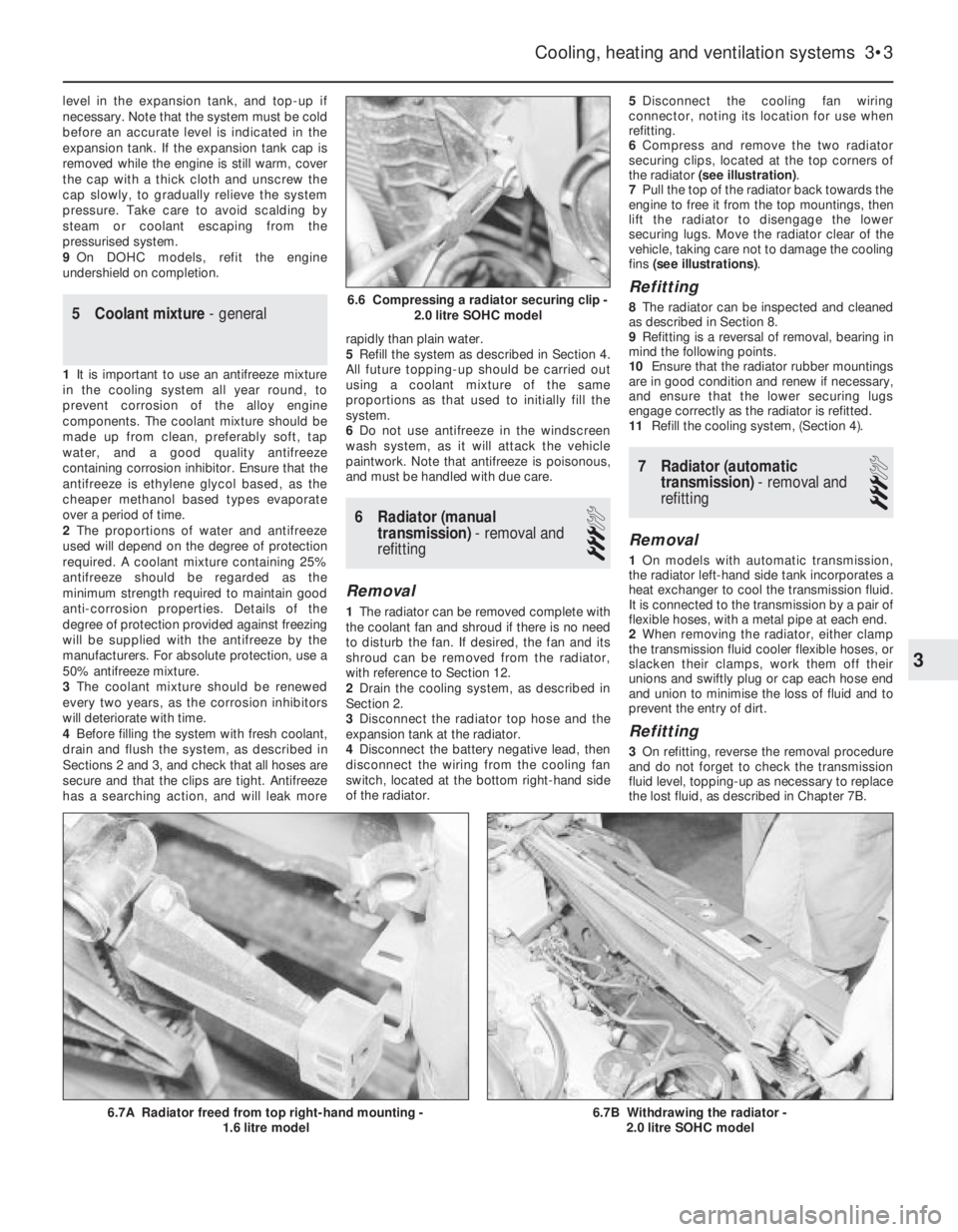
6Compress and remove the two radiator
securing clips, located at the top corners of
the radiator (see illustration).
7Pull the top of the radiator back towards the
engine to free it from the top mountings, then
lift the radiator to disengage the lower
securing lugs. Move the radiator clear of the
vehicle, taking care not to damage the cooling
fins (see illustrations).
Refitting
8The radiator can be inspected and cleaned
as described in Section 8.
9Refitting is a reversal of removal, bearing in
mind the following points.
10Ensure that the radiator rubber mountings
are in good condition and renew if necessary,
and ensure that the lower securing lugs
engage correctly as the radiator is refitted.
11Refill the cooling system, (Section 4).
7Radiator (automatic
transmission) -removal and
refitting
3
Removal
1On models with automatic transmission,
the radiator left-hand side tank incorporates a
heat exchanger to cool the transmission fluid.
It is connected to the transmission by a pair of
flexible hoses, with a metal pipe at each end.
2When removing the radiator, either clamp
the transmission fluid cooler flexible hoses, or
slacken their clamps, work them off their
unions and swiftly plug or cap each hose end
and union to minimise the loss of fluid and to
prevent the entry of dirt.
Refitting
3On refitting, reverse the removal procedure
and do not forget to check the transmission
fluid level, topping-up as necessary to replace
the lost fluid, as described in Chapter 7B.
Cooling, heating and ventilation systems 3•3
6.7B Withdrawing the radiator -
2.0 litre SOHC model6.7A Radiator freed from top right-hand mounting -
1.6 litre model
6.6 Compressing a radiator securing clip -
2.0 litre SOHC model
3
Page 242 of 525
Spare parts are available from many
sources, for example: Vauxhall dealers, other
garages and accessory shops, and motor
factors. Our advice regarding spare part
sources is as follows.
Officially appointed Vauxhall
dealers
This is the best source of parts that are
peculiar to your car and are otherwise not
generally available (e.g. complete cylinder
heads, transmission components, badges,
interior trim, etc.). It is also the only place at
which you should buy parts if your vehicle is
still under warranty -use of non-Vauxhall
components may invalidate the warranty. To
be sure of obtaining the correct parts it willalways be necessary to give the storeman
your car’s vehicle identification number, and if
possible, to take the “old” parts along for
positive identification. Remember that many
parts are available on a factory exchange
scheme -any parts returned should always be
clean! It obviously makes good sense to go
straight to the specialists on your car for this
type of part for they are best equipped to
supply you.
Other garages and accessory
shops
These are often very good places to buy
materials and components needed for the
maintenance of your car (e.g. oil filters, spark
plugs, bulbs, drivebelts, oils and greases,touch-up paint, filler paste, etc.). They also
sell general accessories, usually have
convenient opening hours, charge lower
prices and can often be found not far from
home.
Motor factors
Good factors will stock all the more
important components that wear out
relatively quickly (e.g. clutch components,
pistons, valves, exhaust systems, brake
cylinders/pipes/hoses/seals/shoes and pads,
etc.). Motor factors will often provide new or
reconditioned components on a part
exchange basis -this can save considerable
amount of money.
Modifications are a continuing and
unpublished process in vehicle manufacture,
quite apart from major model changes. Spare
parts manuals and lists are compiled upon a
numerical basis, the individual vehicle
numbers being essential to correct identifi-
cation of the component required.
When ordering spare parts, always give as
much information as possible. Quote the car
model, year of manufacture and vehicle iden-
tification and/or engine numbers as
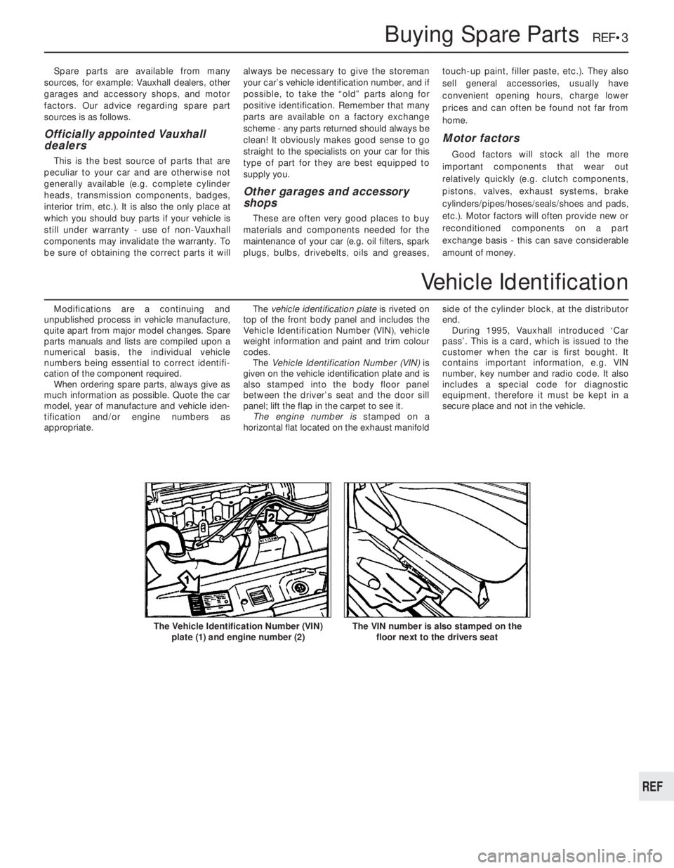
appropriate.The vehicle identification plate is riveted on
top of the front body panel and includes the
Vehicle Identification Number (VIN), vehicle
weight information and paint and trim colour
codes.
The Vehicle Identification Number (VIN) is
given on the vehicle identification plate and is
also stamped into the body floor panel
between the driver’s seat and the door sill
panel; lift the flap in the carpet to see it.
The engine number is stamped on a
horizontal flat located on the exhaust manifoldside of the cylinder block, at the distributor
end.
During 1995, Vauxhall introduced ‘Car
pass’. This is a card, which is issued to the
customer when the car is first bought. It
contains important information, e.g. VIN
number, key number and radio code. It also
includes a special code for diagnostic
equipment, therefore it must be kept in a
secure place and not in the vehicle.
Buying Spare Parts REF•3
The VIN number is also stamped on the
floor next to the drivers seatThe Vehicle Identification Number (VIN)
plate (1) and engine number (2)
REF
Vehicle Identification
Page 251 of 525
Engine
m mEngine fails to rotate when attempting to start
m mEngine rotates, but will not start
m mEngine difficult to start when cold
m mEngine difficult to start when hot
m mStarter motor noisy or excessively rough in engagement
m mEngine starts, but stops immediately
m mEngine idles erratically
m mEngine misfires at idle speed
m mEngine misfires throughout the driving speed range
m mEngine hesitates on acceleration
m mEngine stalls
m mEngine lacks power
m mEngine backfires
m mOil pressure warning light illuminated with engine running
m mEngine runs-on after switching off
m mEngine noises
Cooling system
m
mOverheating
m mOvercooling
m mExternal coolant leakage
m mInternal coolant leakage
m mCorrosion
Fuel and exhaust systems
m
mExcessive fuel consumption
m mFuel leakage and/or fuel odour
m mExcessive noise or fumes from exhaust system
Clutch
m
mPedal travels to floor - no pressure or very little resistance
m mClutch fails to disengage (unable to select gears)
m mClutch slips (engine speed increases, with no increase in vehicle
speed)
m mJudder as clutch is engaged
m mNoise when depressing or releasing clutch pedal
Manual transmission
m
mNoisy in neutral with engine running
m mNoisy in one particular gear
m mDifficulty engaging gears
m mJumps out of gear
m mVibration
m mLubricant leaks
Automatic transmission
m
mFluid leakage
m mTransmission fluid brown, or has burned smell
m mGeneral gear selection problems
m mTransmission will not downshift (kickdown) with accelerator fully
depressed
m mEngine will not start in any gear, or starts in gears other than Park
or Neutral
m mTransmission slips, shifts roughly, is noisy, or has no drive in
forward or reverse gears
Driveshafts
m mClicking or knocking noise on turns (at slow speed on full-lock)
m mVibration when accelerating or decelerating
Braking system
m
mVehicle pulls to one side under braking
m mNoise (grinding or high-pitched squeal) when brakes applied
m mExcessive brake pedal travel
m mBrake pedal feels spongy when depressed
m mExcessive brake pedal effort required to stop vehicle
m mJudder felt through brake pedal or steering wheel when braking
m mBrakes binding
m mRear wheels locking under normal braking
Suspension and steering systems
m
mVehicle pulls to one side
m mWheel wobble and vibration
m mExcessive pitching and/or rolling around corners, or during
braking
m mWandering or general instability
m mExcessively stiff steering
m mExcessive play in steering
m mLack of power assistance
m mTyre wear excessive
Electrical system
m
mBattery will not hold a charge for more than a few days
m mIgnition/no-charge warning light remains illuminated with engine
running
m mIgnition/no-charge warning light fails to come on
m mLights inoperative
m mInstrument readings inaccurate or erratic
m mHorn inoperative, or unsatisfactory in operation
m mWindscreen/tailgate wipers inoperative, or unsatisfactory in
operation
m mWindscreen/tailgate washers inoperative, or unsatisfactory in
operation
m mElectric windows inoperative, or unsatisfactory in operation
m mCentral locking system inoperative, or unsatisfactory in operation
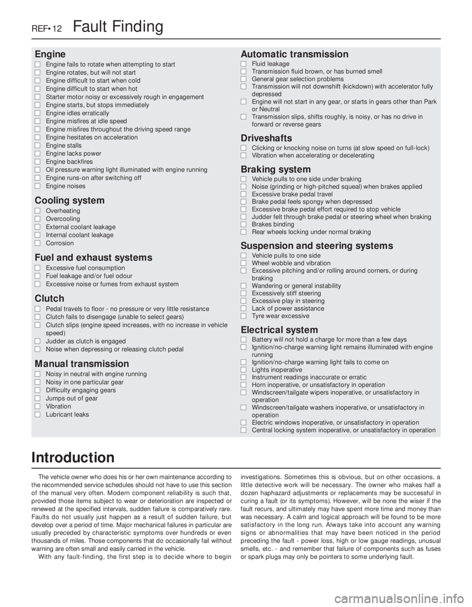
The vehicle owner who does his or her own maintenance according to
the recommended service schedules should not have to use this section
of the manual very often. Modern component reliability is such that,
provided those items subject to wear or deterioration are inspected or
renewed at the specified intervals, sudden failure is comparatively rare.
Faults do not usually just happen as a result of sudden failure, but
develop over a period of time. Major mechanical failures in particular are
usually preceded by characteristic symptoms over hundreds or even
thousands of miles. Those components that do occasionally fail without
warning are often small and easily carried in the vehicle.
With any fault-finding, the first step is to decide where to begininvestigations. Sometimes this is obvious, but on other occasions, a
little detective work will be necessary. The owner who makes half a
dozen haphazard adjustments or replacements may be successful in
curing a fault (or its symptoms). However, will be none the wiser if the
fault recurs, and ultimately may have spent more time and money than
was necessary. A calm and logical approach will be found to be more
satisfactory in the long run. Always take into account any warning
signs or abnormalities that may have been noticed in the period
preceding the fault - power loss, high or low gauge readings, unusual
smells, etc. - and remember that failure of components such as fuses
or spark plugs may only be pointers to some underlying fault.
REF•12Fault Finding
Introduction
Page 254 of 525
Excessive fuel consumption
MAir filter element dirty or clogged (Chapter 1).
MChoke cable incorrectly adjusted, or choke sticking - carburettor
models (Chapter 4A).
MFuel injection system fault - fuel-injected models (Chapter 4B).
MIgnition timing incorrect/ignition system fault (Chapters 1 and 5).
MTyres under-inflated (Chapter 1).
Fuel leakage and/or fuel odour
MDamaged or corroded fuel tank, pipes or connections (Chapter 4A
or 4B).
MCarburettor float chamber flooding (float height incorrect) -
carburettor models (Chapter 4A).
Excessive noise or fumes from exhaust system
MLeaking exhaust system or manifold joints (Chapters 1 and 4C).
MLeaking, corroded or damaged silencers or pipe (Chapters 1 and 4C).
MBroken mountings causing body or suspension contact (Chapter 1).
Pedal travels to floor - no pressure or very little
resistance
MBroken clutch cable (Chapter 6).
MIncorrect clutch cable adjustment (Chapter 6).
MBroken clutch release bearing or fork (Chapter 6).
MBroken diaphragm spring in clutch pressure plate (Chapter 6).
Clutch fails to disengage (unable to select gears).
MIncorrect clutch cable adjustment (Chapter 6).
MClutch disc sticking on transmission input shaft splines (Chapter 6).
MClutch disc sticking to flywheel or pressure plate (Chapter 6).
MFaulty pressure plate assembly (Chapter 6).
MClutch release mechanism worn or incorrectly assembled (Chapter 6).
Clutch slips (engine speed increases, with no
increase in vehicle speed).
MIncorrect clutch cable adjustment (Chapter 6).
MClutch disc linings excessively worn (Chapter 6).MClutch disc linings contaminated with oil or grease (Chapter 6).
MFaulty pressure plate or weak diaphragm spring (Chapter 6).
Judder as clutch is engaged
MClutch disc linings contaminated with oil or grease (Chapter 6).
MClutch disc linings excessively worn (Chapter 6).
MClutch cable sticking or frayed (Chapter 6).
MFaulty or distorted pressure plate or diaphragm spring (Chapter 6).
MWorn or loose engine or transmission mountings (Chapter 2A or 2B).
MClutch disc hub or transmission input shaft splines worn (Chapter 6).
Noise when depressing or releasing clutch pedal
MWorn clutch release bearing (Chapter 6).
MWorn or dry clutch pedal bushes (Chapter 6).
MFaulty pressure plate assembly (Chapter 6).
MPressure plate diaphragm spring broken (Chapter 6).
MBroken clutch disc cushioning springs (Chapter 6).
Fault Finding REF•15
REF
Overheating
MInsufficient coolant in system (Chapter 1).
MThermostat faulty (Chapter 3).
MRadiator core blocked, or grille restricted (Chapter 3).
MElectric cooling fan or thermoswitch faulty (Chapter 3).
MPressure cap faulty (Chapter 3).
MIgnition timing incorrect/ignition system fault (Chapters 1 and 5).
MInaccurate temperature gauge sender unit (Chapter 3).
MAirlock in cooling system (Chapter 1).
Overcooling
MThermostat faulty (Chapter 3).
MInaccurate temperature gauge sender unit (Chapter 3).
External coolant leakage
MDeteriorated or damaged hoses or hose clips (Chapter 1).
MRadiator core or heater matrix leaking (Chapter 3).
MPressure cap faulty (Chapter 3).
MWater pump seal leaking (Chapter 3).
MBoiling due to overheating (Chapter 3).
MCore plug leaking (Chapter 2A).
Internal coolant leakage
MLeaking cylinder head gasket (Chapter 2A or 2B).
MCracked cylinder head or cylinder bore (Chapter 2A or 2B).
Corrosion
MInfrequent draining and flushing (Chapter 1).
MIncorrect coolant mixture or inappropriate coolant type (Chapter 1).
Cooling system
Clutch
Fuel and exhaust systems