1988 OPEL CALIBRA check transmission fluid
[x] Cancel search: check transmission fluidPage 207 of 525
30With the engine removed, the
transmission can be supported by placing a
length of wood between the bellhousing and
the front suspension subframe. Once the
wooden support is in place, remove the trolley
jack from under the transmission.
Refitting
Note: New left and right-hand
engine/transmission mounting-to-body bolts
must be used on refitting.
31Use an M10 x 1.25 bottoming tap to clean
the threads in the torque converters threaded
bosses and ensure that new bolts are
available for reassembly, where applicable.
32Support the transmission with a trolley
jack and remove the length of wood from
between the bellhousing and the subframe.
33Support the engine with the hoist and
lifting tackle, and gently lower it into position
in the engine compartment.
34Mate the engine and transmission
together, ensuring that the transmission
locates on the dowels in the cylinder block,
then refit the three upper
engine-to-transmission bolts.
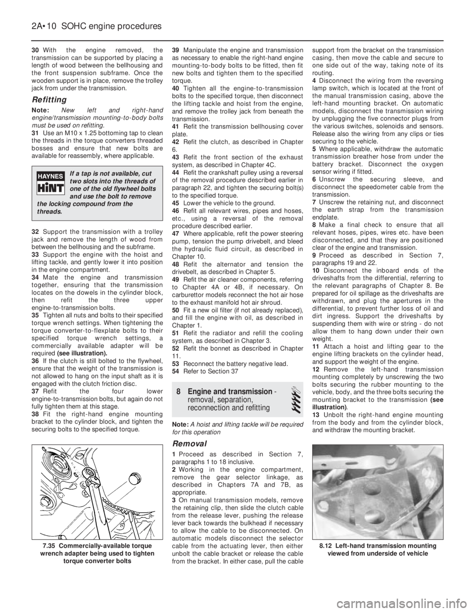
35Tighten all nuts and bolts to their specified
torque wrench settings. When tightening the
torque converter-to-flexplate bolts to their
specified torque wrench settings, a
commercially available adapter will be
required (see illustration).
36If the clutch is still bolted to the flywheel,
ensure that the weight of the transmission is
not allowed to hang on the input shaft as it is
engaged with the clutch friction disc.
37Refit the four lower
engine-to-transmission bolts, but again do not
fully tighten them at this stage.
38Fit the right-hand engine mounting
bracket to the cylinder block, and tighten the
securing bolts to the specified torque.39Manipulate the engine and transmission
as necessary to enable the right-hand engine
mounting-to-body bolts to be fitted, then fit
new bolts and tighten them to the specified
torque.
40Tighten all the engine-to-transmission
bolts to the specified torque, then disconnect
the lifting tackle and hoist from the engine,
and remove the trolley jack from beneath the
transmission.
41Refit the transmission bellhousing cover
plate.
42Refit the clutch, as described in Chapter
6.
43Refit the front section of the exhaust
system, as described in Chapter 4C.
44Refit the crankshaft pulley using a reversal
of the removal procedure described earlier in
paragraph 22, and tighten the securing bolt(s)
to the specified torque.
45Lower the vehicle to the ground.
46Refit all relevant wires, pipes and hoses,
etc., using a reversal of the removal
procedure described earlier.
47Where applicable, refit the power steering
pump, tension the pump drivebelt, and bleed
the hydraulic fluid circuit, as described in
Chapter 10.
48Refit the alternator and tension the
drivebelt, as described in Chapter 5.
49Refit the air cleaner components, referring
to Chapter 4A or 4B, if necessary. On
carburettor models reconnect the hot air hose
to the exhaust manifold hot air shroud.
50Fit a new oil filter (if not already replaced),
and fill the engine with oil, as described in
Chapter 1.
51Refit the radiator and refill the cooling
system, as described in Chapter 3.
52Refit the bonnet as described in Chapter
11.
53Reconnect the battery negative lead.
54Refer to Section 37
8Engine and transmission -
removal, separation,
reconnection and refitting
4
Note: A hoist and lifting tackle will be required
for this operation
Removal
1Proceed as described in Section 7,
paragraphs 1 to 18 inclusive.
2Working in the engine compartment,
remove the gear selector linkage, as
described in Chapters 7A and 7B, as
appropriate.
3On manual transmission models, remove
the retaining clip, then slide the clutch cable
from the release lever, pushing the release
lever back towards the bulkhead if necessary
to allow the cable to be disconnected. On
automatic models disconnect the selector
cable from the actuating lever, then either
unbolt the cable bracket or release the cable
from the bracket. In either case, pull the cablesupport from the bracket on the transmission
casing, then move the cable and secure to
one side out of the way, taking note of its
routing.
4Disconnect the wiring from the reversing
lamp switch, which is located at the front of
the manual transmission casing, above the
left-hand mounting bracket. On automatic
models, disconnect the transmission wiring
by unplugging the five connector plugs from
the various switches, solenoids and sensors.
Release also the wiring from any clips or ties
securing to the vehicle.
5Where applicable, withdraw the automatic
transmission breather hose from under the
battery bracket. Disconnect the oxygen
sensor wiring if fitted.
6Unscrew the securing sleeve, and
disconnect the speedometer cable from the
transmission.
7Unscrew the retaining nut, and disconnect
the earth strap from the transmission
endplate.
8Make a final check to ensure that all
relevant hoses, pipes, wires etc. have been
disconnected, and that they are positioned
clear of the engine and transmission.
9Proceed as described in Section 7,
paragraphs 19 and 22.
10Disconnect the inboard ends of the
driveshafts from the differential, referring to
the relevant paragraphs of Chapter 8. Be
prepared for oil spillage as the driveshafts are
withdrawn, and plug the apertures in the
differential, to prevent further loss of oil and
dirt ingress. Support the driveshafts by
suspending them with wire or string - do not
allow them to hang down under their own
weight.
11Attach a hoist and lifting gear to the
engine lifting brackets on the cylinder head,
and support the weight of the engine.
12Remove the left-hand transmission
mounting completely by unscrewing the two
bolts securing the rubber mounting to the
vehicle, body, and the three bolts securing the
mounting bracket to the transmission (see
illustration).
13Unbolt the right-hand engine mounting
from the body and from the cylinder block,
and withdraw the mounting bracket.
2A•10SOHC engine procedures
8.12 Left-hand transmission mounting
viewed from underside of vehicle7.35 Commercially-available torque
wrench adapter being used to tighten
torque converter bolts
If a tap is not available, cut
two slots into the threads of
one of the old flywheel bolts
and use the bolt to remove
the locking compound from the
threads.
Page 208 of 525
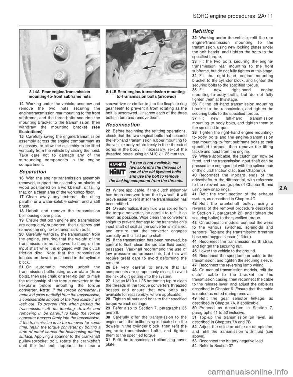
14Working under the vehicle, unscrew and
remove the two nuts securing the
engine/transmission rear mounting to the front
subframe, and the three bolts securing the
mounting bracket to the transmission, then
withdraw the mounting bracket (see
illustrations).
15Carefully swing the engine/transmission
assembly across the engine compartment as
necessary, to allow the assembly to be lifted
vertically from the vehicle by raising the hoist.
Take care not to damage any of the
surrounding components in the engine
compartment.
Separation
16With the engine/transmission assembly
removed, support the assembly on blocks of
wood positioned on a workbench, or failing
that, on a clean area of the workshop floor.
17Clean away any external dirt using
paraffin or a water-soluble solvent and a stiff
brush.
18Unbolt and remove the transmission
bellhousing cover plate.
19Ensure that both engine and transmission
are adequately supported, then unscrew and
remove the engine-to-transmission bolts.
20Carefully withdraw the transmission from
the engine, ensuring that the weight of the
transmission is not allowed to hang on the
input shaft while it is engaged with the clutch
friction disc. Note that the transmission
locates on dowels positioned in the cylinder
block.
21On automatic models unbolt the
transmission bellhousing cover plate (three
bolts), then use chalk or a felt-tip pen to mark
the relationship of the torque converter to the
flexplate before unbolting the torque
converter. Note:If the torque converter is
removed (even partially) from the transmission,
a considerable amount of the fluid inside it will
leak out. To prevent this, when prising the
transmission off its locating dowels and
removing it, be careful to keep the torque
converter pressed firmly into the transmission.
If the transmission is to be removed for some
time, retain the torque converter by bolting a
strip of metal across the bellhousing mating
surface. Applying a spanner to the crankshaft
pulley/sprocket bolt, rotate the crankshaft
until the first bolt appears, then use ascrewdriver or similar to jam the flexplate ring
gear teeth to prevent it from rotating as the
bolt is unscrewed. Unscrew each of the three
bolts in turn and remove them.
Reconnection
22Before beginning the refitting operations,
check that the two original bolts that secured
the left-hand transmission rubber mounting to
the vehicle body rotate freely in their threaded
bores in the body. If necessary, re-cut the
threaded bores using an M10 x 1.25 mm tap.
23Where applicable, if the clutch assembly
has been removed from the flywheel, it will
prove easier to refit after the transmission has
been refitted.
24On automatics, if any fluid was spilled from
the torque converter, be careful to refill it as
much as possible. Wipe clean the converter’s
spigot to prevent damage to the transmission’s
input shaft oil seal as the converter is installed,
and ensure that the converter engages
correctly on the fluid pump shaft.
25If the transmission has been renewed, be
careful to flush clean the radiator fluid cooler
passages. Vauxhall recommend the use of
low-pressure compressed air, but this will
require great care to avoid deforming the
radiator.
26Be very careful to ensure that all
components are scrupulously clean, to avoid
the risk of dirt getting into the system.
27Use an M10 x 1.25 bottoming tap to clean
the threads in the torque converters threaded
bosses and ensure that new bolts are
available for reassembly, where applicable.
28Tighten all nuts and bolts to their specified
torque wrench settings.
29Refer also to Section 7, paragraphs 35
and 36.
30Carefully offer the transmission to the
engine until the bellhousing is located on the
dowels in the cylinder block, then refit the
engine-to-transmission bolts, and tighten
them to the specified torque.
31Refit the transmission bellhousing cover
plate.
Refitting
32Working under the vehicle, refit the rear
engine/transmission mounting to the
transmission, using new locking plates under
the bolt heads, and tighten the bolts to the
specified torque.
33Fit the two bolts securing the engine/
transmission rear mounting to the front
subframe, but do not fully tighten at this stage.
34Fit the right-hand engine mounting
bracket to the cylinder block, and tighten the
securing bolts to the specified torque.
35Fit new right-hand engine
mounting-to-body bolts, but do not fully
tighten them at this stage.
36Fit the left-hand transmission mounting
bracket to the transmission, and tighten the
securing bolts to the specified torque.
37Fit new left-hand transmission
mounting-to-body bolts, and tighten them to
the specified torque.
38Tighten the right-hand engine mounting-
to-body bolts and the engine/transmission
rear mounting-to-front subframe bolts to their
specified torques, then remove the lifting
tackle and hoist from the engine.
39Where applicable, the clutch can now be
fitted, and the transmission input shaft can be
pressed into engagement with the splined hub
of the clutch friction disc, (see Chapter 5).
40Reconnect the inboard ends of the
driveshafts to the differential, with reference
to the relevant paragraphs of Chapter 8, and
using new snap rings.
41Refit the front section of the exhaust
system, as described in Chapter 4C.
42Refit the crankshaft pulley, using a
reversal of the removal procedure described
in Section 7, paragraph 22, and tighten the
securing bolt(s) to the specified torque.
43On automatic models, connect the wires
to the various switches, solenoids and
sensors. Replace the transmission breather
hose and oxygen sensor (if fitted).
44Reconnect the transmission earth strap,
and tighten the securing nut.
45Lower the vehicle to the ground.
46Reconnect the speedometer cable to the
transmission, and tighten the securing sleeve.
47Reconnect the reversing lamp wiring.
48On manual transmission models, refit the
clutch cable to the bracket on the
transmission casing, then reconnect the cable
to the release lever, and adjust the cable as
described in Chapter 6. Ensure that the cable
is routed as noted during removal.
49Refit the gear selector linkage, as
described in Chapter 7A, if applicable.
50Proceed as described in Section 7,
paragraphs 41 to 52 inclusive.
51Top-up the transmission oil level, as
described in Chapters 7A and 7B.
52Adjust the selector cable on completion,
and refill the transmission with fluid (see
above).
53Reconnect the battery negative lead.
54Refer to Section 37
SOHC engine procedures 2A•11
8.14B Rear engine/transmission mounting-
to-transmission bolts (arrowed)8.14A Rear engine/transmission
mounting-to-front subframe nuts
2A
If a tap is not available, cut
two slots into the threads of
one of the old flywheel bolts
and use the bolt to remove
the locking compound from the threads.
Page 231 of 525
5Note that the rubber plug located next to
the bellhousing flange on the cylinder block
covers the aperture for the installation of a
diagnostic TDC sensor. The sensor, when
connected to a monitoring unit, indicates TDC
from the position of the pins set into the
crankshaft balance weight.
37Examination and renovation
-general
4
General
1With the engine completely stripped, clean all
components and examine them for wear. Each
component should be checked, and where
necessary renewed or renovated, as described
in the relevant Sections of this Chapter.
2Renew main and big-end bearing shells as
a matter of course, unless it is known that
they have had little wear, and are in perfect
condition.
3If in doubt whether to renew a component
that is still just serviceable, consider the time
and effort that will be incurred should the
component fail at an early date after rebuild.
Obviously, the age and expected life of the
vehicle must influence the standards applied.4Gaskets, oil seals and O-rings must all be
renewed as a matter of routine. Flywheel,
cylinder head, and main and big-end bearing
cap bolts must be renewed, because of the
high stress to which they are subjected.
5Renew the engine core plugs while they are
easily accessible, if they show signs of
leakage. Knock out the old plugs with a
hammer and chisel or punch. Clean the plug
seats, smear the new plugs with sealing
compound, and tap them squarely into
position.
38Initial start-up after major
overhaul or repair
2
1Make a final check to ensure that
everything has been reconnected to the
engine, and that no rags or tools have been
left in the engine compartment.
2Check that oil and coolant levels are
correct.
3Start the engine. This may take a little longer
than usual, as fuel is pumped to the engine.
4Check that the oil pressure warning lamp
goes out when the engine starts. This may
take a few seconds as the new oil filter fills
with oil.5Run the engine at a fast tickover, and check
for leaks of oil, fuel and coolant. If a new
camshaft has been fitted, pay careful
attention to the running-in procedure given in
Section 18, paragraphs 17 and 18. Where
applicable, check the power steering and/or
automatic transmission fluid cooler unions for
leakage. Some smoke and odd smells may be
experienced, as assembly lubricants and
sealers burn off the various components.
6Bring the engine to normal operating
temperature. Check the ignition timing, idle
speed and the mixture (where applicable), as
described in Chapter 4A or 4B.
7Allow the engine to cool, then recheck the
oil and coolant levels. Top-up if necessary
8If new bearings, pistons, etc., have been
fitted, the engine should be run-in at reduced
speeds and loads for the first 500 miles (800
km) or so. It is beneficial to change the engine
oil and filter after this mileage.
2A•34SOHC engine procedures
Page 232 of 525
3
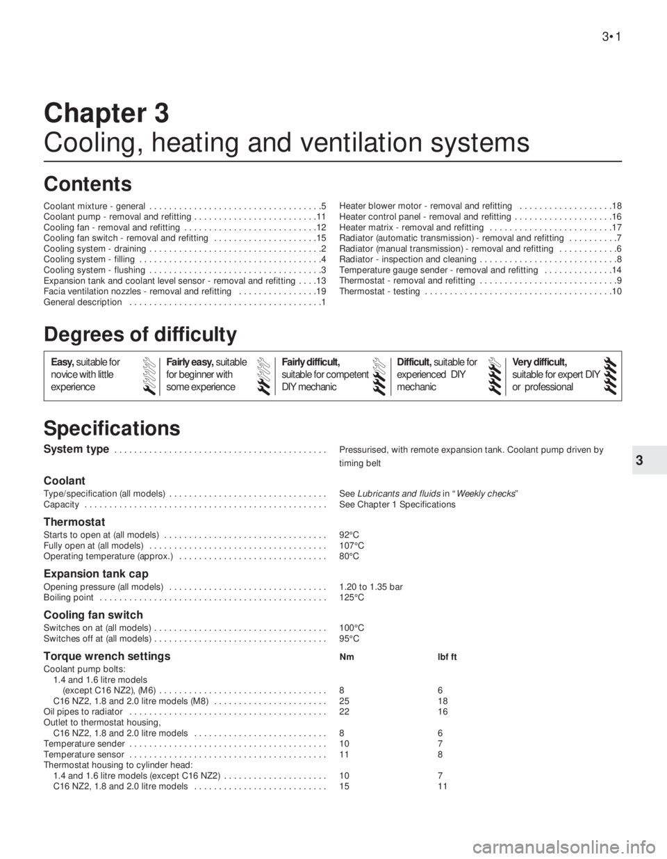
System type . . . . . . . . . . . . . . . . . . . . . . . . . . . . . . . . . . . . . . . . . . . Pressurised, with remote expansion tank. Coolant pump driven by
timing belt
Coolant
Type/specification (all models) . . . . . . . . . . . . . . . . . . . . . . . . . . . . . . . . See Lubricants and fluidsin “Weekly checks”
Capacity . . . . . . . . . . . . . . . . . . . . . . . . . . . . . . . . . . . . . . . . . . . . . . . . . See Chapter 1 Specifications
Thermostat
Starts to open at (all models) . . . . . . . . . . . . . . . . . . . . . . . . . . . . . . . . . 92°C
Fully open at (all models) . . . . . . . . . . . . . . . . . . . . . . . . . . . . . . . . . . . . 107°C
Operating temperature (approx.) . . . . . . . . . . . . . . . . . . . . . . . . . . . . . . 80°C
Expansion tank cap
Opening pressure (all models) . . . . . . . . . . . . . . . . . . . . . . . . . . . . . . . . 1.20 to 1.35 bar
Boiling point . . . . . . . . . . . . . . . . . . . . . . . . . . . . . . . . . . . . . . . . . . . . . . 125°C
Cooling fan switch
Switches on at (all models) . . . . . . . . . . . . . . . . . . . . . . . . . . . . . . . . . . . 100°C
Switches off at (all models) . . . . . . . . . . . . . . . . . . . . . . . . . . . . . . . . . . . 95°C
Torque wrench settingsNm lbf ft
Coolant pump bolts:
1.4 and 1.6 litre models
(except C16 NZ2), (M6) . . . . . . . . . . . . . . . . . . . . . . . . . . . . . . . . . . 8 6
C16 NZ2, 1.8 and 2.0 litre models (M8) . . . . . . . . . . . . . . . . . . . . . . . 25 18
Oil pipes to radiator . . . . . . . . . . . . . . . . . . . . . . . . . . . . . . . . . . . . . . . . 22 16
Outlet to thermostat housing,
C16 NZ2, 1.8 and 2.0 litre models . . . . . . . . . . . . . . . . . . . . . . . . . . . 8 6
Temperature sender . . . . . . . . . . . . . . . . . . . . . . . . . . . . . . . . . . . . . . . . 10 7
Temperature sensor . . . . . . . . . . . . . . . . . . . . . . . . . . . . . . . . . . . . . . . . 11 8
Thermostat housing to cylinder head:
1.4 and 1.6 litre models (except C16 NZ2) . . . . . . . . . . . . . . . . . . . . . 10 7
C16 NZ2, 1.8 and 2.0 litre models . . . . . . . . . . . . . . . . . . . . . . . . . . . 15 11
Chapter 3
Cooling, heating and ventilation systems
Coolant mixture - general . . . . . . . . . . . . . . . . . . . . . . . . . . . . . . . . . . .5
Coolant pump - removal and refitting . . . . . . . . . . . . . . . . . . . . . . . . .11
Cooling fan - removal and refitting . . . . . . . . . . . . . . . . . . . . . . . . . . .12
Cooling fan switch - removal and refitting . . . . . . . . . . . . . . . . . . . . .15
Cooling system - draining . . . . . . . . . . . . . . . . . . . . . . . . . . . . . . . . . . .2
Cooling system - filling . . . . . . . . . . . . . . . . . . . . . . . . . . . . . . . . . . . . .4
Cooling system - flushing . . . . . . . . . . . . . . . . . . . . . . . . . . . . . . . . . . .3
Expansion tank and coolant level sensor - removal and refitting . . . .13
Facia ventilation nozzles - removal and refitting . . . . . . . . . . . . . . . .19
General description . . . . . . . . . . . . . . . . . . . . . . . . . . . . . . . . . . . . . . .1Heater blower motor - removal and refitting . . . . . . . . . . . . . . . . . . .18
Heater control panel - removal and refitting . . . . . . . . . . . . . . . . . . . .16
Heater matrix - removal and refitting . . . . . . . . . . . . . . . . . . . . . . . . .17
Radiator (automatic transmission) - removal and refitting . . . . . . . . . .7
Radiator (manual transmission) - removal and refitting . . . . . . . . . . . .6
Radiator - inspection and cleaning . . . . . . . . . . . . . . . . . . . . . . . . . . . .8
Temperature gauge sender - removal and refitting . . . . . . . . . . . . . .14
Thermostat - removal and refitting . . . . . . . . . . . . . . . . . . . . . . . . . . . .9
Thermostat - testing . . . . . . . . . . . . . . . . . . . . . . . . . . . . . . . . . . . . . .10
3•1
Specifications Contents
Easy,suitable for
novice with little
experienceFairly easy,suitable
for beginner with
some experienceFairly difficult,
suitable for competent
DIY mechanic
Difficult,suitable for
experienced DIY
mechanicVery difficult,
suitable for expert DIY
or professional
Degrees of difficulty
54321
Page 234 of 525
level in the expansion tank, and top-up if
necessary. Note that the system must be cold
before an accurate level is indicated in the
expansion tank. If the expansion tank cap is
removed while the engine is still warm, cover
the cap with a thick cloth and unscrew the
cap slowly, to gradually relieve the system
pressure. Take care to avoid scalding by
steam or coolant escaping from the
pressurised system.
9On DOHC models, refit the engine
undershield on completion.
5Coolant mixture -general
1It is important to use an antifreeze mixture
in the cooling system all year round, to
prevent corrosion of the alloy engine
components. The coolant mixture should be
made up from clean, preferably soft, tap
water, and a good quality antifreeze
containing corrosion inhibitor. Ensure that the
antifreeze is ethylene glycol based, as the
cheaper methanol based types evaporate
over a period of time.
2The proportions of water and antifreeze
used will depend on the degree of protection
required. A coolant mixture containing 25%
antifreeze should be regarded as the
minimum strength required to maintain good
anti-corrosion properties. Details of the
degree of protection provided against freezing
will be supplied with the antifreeze by the
manufacturers. For absolute protection, use a
50% antifreeze mixture.
3The coolant mixture should be renewed
every two years, as the corrosion inhibitors
will deteriorate with time.
4Before filling the system with fresh coolant,
drain and flush the system, as described in
Sections 2 and 3, and check that all hoses are
secure and that the clips are tight. Antifreeze
has a searching action, and will leak morerapidly than plain water.
5Refill the system as described in Section 4.
All future topping-up should be carried out
using a coolant mixture of the same
proportions as that used to initially fill the
system.
6Do not use antifreeze in the windscreen
wash system, as it will attack the vehicle
paintwork. Note that antifreeze is poisonous,
and must be handled with due care.
6Radiator (manual
transmission) -removal and
refitting
3
Removal
1The radiator can be removed complete with
the coolant fan and shroud if there is no need
to disturb the fan. If desired, the fan and its
shroud can be removed from the radiator,
with reference to Section 12.
2Drain the cooling system, as described in
Section 2.
3Disconnect the radiator top hose and the
expansion tank at the radiator.
4Disconnect the battery negative lead, then
disconnect the wiring from the cooling fan
switch, located at the bottom right-hand side
of the radiator.5Disconnect the cooling fan wiring
connector, noting its location for use when
refitting.
6Compress and remove the two radiator
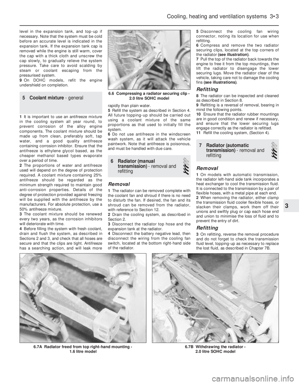
securing clips, located at the top corners of
the radiator (see illustration).
7Pull the top of the radiator back towards the
engine to free it from the top mountings, then
lift the radiator to disengage the lower
securing lugs. Move the radiator clear of the
vehicle, taking care not to damage the cooling
fins (see illustrations).
Refitting
8The radiator can be inspected and cleaned
as described in Section 8.
9Refitting is a reversal of removal, bearing in
mind the following points.
10Ensure that the radiator rubber mountings
are in good condition and renew if necessary,
and ensure that the lower securing lugs
engage correctly as the radiator is refitted.
11Refill the cooling system, (Section 4).
7Radiator (automatic
transmission) -removal and
refitting
3
Removal
1On models with automatic transmission,
the radiator left-hand side tank incorporates a
heat exchanger to cool the transmission fluid.
It is connected to the transmission by a pair of
flexible hoses, with a metal pipe at each end.
2When removing the radiator, either clamp
the transmission fluid cooler flexible hoses, or
slacken their clamps, work them off their
unions and swiftly plug or cap each hose end
and union to minimise the loss of fluid and to
prevent the entry of dirt.
Refitting
3On refitting, reverse the removal procedure
and do not forget to check the transmission
fluid level, topping-up as necessary to replace
the lost fluid, as described in Chapter 7B.
Cooling, heating and ventilation systems 3•3
6.7B Withdrawing the radiator -
2.0 litre SOHC model6.7A Radiator freed from top right-hand mounting -
1.6 litre model
6.6 Compressing a radiator securing clip -
2.0 litre SOHC model
3
Page 255 of 525
Note:Due to the complexity of the automatic transmission, it is difficult
for the home mechanic to properly diagnose and service this unit. For
problems other than the following, the vehicle should be taken to a
dealer service department or automatic transmission specialist. Do not
be too hasty in removing the transmission if a fault is suspected, as
most of the testing is carried out with the unit still fitted.
Fluid leakage
MAutomatic transmission fluid is usually dark in colour. Fluid leaks
should not be confused with engine oil, which can easily be blown
onto the transmission by airflow.
MTo determine the source of a leak, first remove all built-up dirt and
grime from the transmission housing and surrounding areas using
a degreasing agent, or by steam-cleaning. Drive the vehicle at low
speed, so airflow will not blow the leak far from its source. Raise
and support the vehicle, and determine where the leak is coming
from. The following are common areas of leakage:
a)Fluid pan or “sump” (Chapter 1 and 7B).
b)Dipstick tube (Chapter 1 and 7B).
c)Transmission-to-fluid cooler pipes/unions (Chapter 7B).
Transmission fluid brown, or has burned smell
MTransmission fluid level low, or fluid in need of renewal (Chapter 1).
General gear selection problems
MChapter 7B deals with checking and adjusting the selector cable
on automatic transmissions. The following are common problems
that may be caused by a poorly adjusted cable:a)Engine starting in gears other than Park or Neutral.
b)Indicator panel indicating a gear other than the one actually being
used.
c)Vehicle moves when in Park or Neutral.
d)Poor gear shift quality or erratic gear changes.
MRefer to Chapter 7B for the selector cable adjustment procedure.
Transmission will not downshift (kickdown) with
accelerator pedal fully depressed
MLow transmission fluid level (Chapter 1).
MIncorrect selector cable adjustment (Chapter 7B).
Engine will not start in any gear, or starts in gears
other than Park or Neutral
MIncorrect starter/inhibitor switch adjustment (Chapter 7B).
MIncorrect selector cable adjustment (Chapter 7B).
Transmission slips, shifts roughly, is noisy, or has
no drive in forward or reverse gears
MThere are many probable causes for the above problems, but the
home mechanic should be concerned with only one possibility -
fluid level. Before taking the vehicle to a dealer or transmission
specialist, check the fluid level and condition of the fluid as
described in Chapter 1. Correct the fluid level as necessary, or
change the fluid and filter if needed. If the problem persists,
professional help will be necessary.
Clicking or knocking noise on turns (at slow speed
on full-lock)
MLack of constant velocity joint lubricant, possibly due to damaged
gaiter (Chapter 8).
MWorn outer constant velocity joint (Chapter 8).
Vibration when accelerating or decelerating
MWorn inner constant velocity joint (Chapter 8).
MBent or distorted driveshaft (Chapter 8).
REF•16Fault Finding
Automatic transmission
Driveshafts
Noisy in neutral with engine running
MInput shaft bearings worn (noise apparent with clutch pedal
released, but not when depressed), (Chapter 7A).*
MClutch release bearing worn (noise apparent with clutch pedal
depressed, possibly less when released), (Chapter 6).
Noisy in one particular gear
MWorn, damaged or chipped gear teeth (Chapter 7A).*
Difficulty engaging gears
MClutch fault (Chapter 6).
MWorn or damaged gear linkage (Chapter 7A).
MIncorrectly adjusted gear linkage (Chapter 7A).
MWorn synchroniser units (Chapter 7A).*
Jumps out of gear
MWorn or damaged gear linkage (Chapter 7A).
MIncorrectly adjusted gear linkage (Chapter 7A).MWorn synchroniser units (Chapter 7A).*
MWorn selector forks (Chapter 7A).*
Vibration
MLack of oil (Chapter 1).
MWorn bearings (Chapter 7A).*
Lubricant leaks
MLeaking differential output oil seal (Chapter 7A).
MLeaking housing joint (Chapter 7A).*
MLeaking input shaft oil seal (Chapter 7A).*
* Although the corrective action necessary to remedy the symptoms
described is beyond the scope of the home mechanic, the above
information should be helpful in isolating the cause of the condition.
This should enable the owner can communicate clearly with a
professional mechanic.
Manual transmission
Page 264 of 525
AABS components- 9•2, 9•16
Accelerator cable- 4A•5, 4B•9
Accelerator pedal- 4A•5
Acknowledgements- 0•4
Aerial- 12•17
Air cleaner- 1•3, 1•13, 4A•3, 4B•4
Air box- 4B•5
Air pump/cut off valve- 4C•2
Air temp control- 4B•5
Air vents- 3•8
Airbag- 12•19
Airflow meters- 4B•12
Alternator- 5•5
Alternator V-belt check- 1•12
Anti theft alarm- 12•19
Anti-roll bars- 10•8, 10•13, 10•17
Antifreeze mixture- 0•12, 0•17, 1•2, 3•3
ATF- 0•17, 1•2, 1•11, 7B•3
Automatic choke unit- 4A•9
Automatic transmission- 7B•1 et seq
cooler pipes and hoses - 7B•5
ECU - 7B•5
fault diagnosis - REF•12, REF•16
fluid - 0•17, 1•2, 1•11, 7B•3
kickdown switch - 7B•3
removal and refitting - 7B•6
selector control cable - 7B•4
speed sensors - 7B•6
starter inhibitor switch - 7B•3
temperature sensor - 7B•5
BBattery- 0•6, 0•15, 5•5
Bearings (engine)- 2A•31
Bleeding the brakes- 9•3
Bleeding the power steering- 10•22
Blower motor- 3•7
Body damage- 11•2
Body electrical systems - 12•1 et seq
Bodywork and fittings- 11•1 et seq
Bonnet- 11•4
Bonnet lock/release cable- 11•4
Boot lid- 11•4
Boot lid lock- 11•5
Bores- 2A•33
Brake checks- 1•12,
Braking system- 9•1 et seq
ABS components - 9•2, 9•16
backplate - 9•12
bleeding the brakes - 9•3
brake caliper - 9•8
brake disc - 9•10
brake drum - 9•11
brake fluid pipes and hoses - 9•18
brake lamp switch - 12•5
brake pads - 9•4
brake pedal - 9•21
brake shoes - 9•6
disc shield - 9•13
fault diagnosis - REF•12, REF•17
fluid - 0•13, 0•17handbrake adjustment - 9•18
handbrake cables - 9•19
handbrake lever - 9•20
master cylinder - 9•13
pressure valves - 9•18
vacuum servo unit - 9•15
wheel cylinder - 9•11
Bulbs- 12•2, 12•7, 12•11
Bumpers- 11•11
CCables:
bonnet release - 11•4
clutch - 6•2
handbrake - 9•19
selector automatic transmission - 7B•4
speedometer - 12•18
throttle - 4A•5, 4B•9
Caliper (brake)- 9•8
Camber- 10•1, 10•24
Camshaft- 2A•19, 2B•6
Camshaft housing- 2A•18
Camshaft oil seals- 2A•18
Capacities- 1•2
Carbon canister- 4C•4
Carburettor- 4A•5, 4A•11
Carpets- 11•2
Castor- 10•1, 10•24
Catalytic converter- 4C•3
Central door locking- 12•16
Centre console- 11•18
Cigarette lighter- 12•5
Clock- 12•6
Clutch- 6•1 et seq
cable - 6•2
fault diagnosis - REF•12, REF•15
pedal - 6•3
release bearing - 6•6
removal, inspection and refitting - 6•3
Coil- 5•9
Coil spring (rear)- 10•12, 10•15
Compression test- 2A•8
Computer components- 12•7
Connecting rods- 2A•29
Contents- 0•2
Control units- 4B•16, 7B•5
Conversion factors- REF•2
Coolant- 0•12, 0•17, 1•2, 3•3
Cooling, heating and ventilation systems-
3•1 et seq
blower motor - 3•7
coolant level sensor - 3•5
coolant pump - 3•4
cooling fan - 3•5
draining - 3•2
expansion tank - 3•5
fan switch - 3•6
fault diagnosis - REF•12, REF•15
filling - 3•2
flushing - 3•2
heater control panel - 3•6
heater matrix - 3•7
radiator - 3•3temperature gauge sender - 3•6
thermostat - 3•4
vents - 3•8
Courtesy lamp switch- 12•5
Crankcase ventilation system- 2A•7
Crankshaft- 2A•31
Crankshaft oil seals- 2A•26, 2B•6, 2B•9
Cylinder bores- 2A•33
Cylinder head- 2A•19, 2A•22, 2B•7DDents- 11•2
Depressurising fuel system- 4B•5
Differential bearing oil seal- 7A•3
Dimensions and weights- REF•1
Disc (brake)- 9•10
Distributor- 5•10
Door- 11•6
handle - 11•7
inner trim panel - 11•6
lock key battery - 1•13
mirror - 11•11
Driveshafts- 8•1 et seq
fault diagnosis - REF•12, REF•16
gaiter - 8•4
joint renewal - 8•4
Drum (brake)- 9•11
EEarth fault finding- 12•2
ECU’s - 4B•16, 7B•5
EGR components- 4C•2
Electric windows- 12•15
Electrical fault finding- 12•2
Electrical system (body)- 12•1 et seq
Electrical system- 0•14, 5•2
Electrical system fault diagnosis- REF•12,
REF•18
Electronic control units- 4B•16, 7B•5
Engine:
bearings - 2A•31
camshaft - 2A•19, 2B•6
camshaft housing - 2A•18
camshaft oil seals - 2A•18, 2B•6
codes - 2A•1, 2B•1
compartment - 0•10, 1•5
compression test - 2A•8
connecting rods - 2A•29
crankcase ventilation - 2A•7
crankshaft - 2A•31
crankshaft oil seals - 2A•26, 2B•6, 2B•9
cylinder bores - 2A•33
cylinder head - 2A•19, 2A•22, 2B•7
dismantling - 2A•12
DOHC - 2B•1 et seq
electrical systems - 5•1 et seq
fault diagnosis - REF•12, REF•13
flexplate (automatic transmission) - 2A•26
flywheel - 2A•26
main and big-end bearings - 2A•31
mountings (engine/transmission) - 2A•12,
2B•3
Index REF•25
REF
Note:References throughout this index are in the form - “Chapter number” • “page number”
Page 265 of 525
oil and filter renewal - 0•17, 1•2, 1•9
oil cooler - 2B•10
oil level - 0•12
oil pump - 2A•28, 2B•9
piston rings - 2A•30
piston/connecting rod - 2A•29
removal - 2A•8, 2B•3
SOHC - 2A•1 et seq
sump - 2A•27, 2B•9
timing belt - 2A•13, 2B•3, 2B•6
undershield - 11•13
valve lifters - 2A•24, 2B•9
valves - 2A•5, 2B•2
Environmental considerations- REF•4
Exhaust manifold- 4C•5
Exhaust system check- 1•11, 4C•5
Expansion tank- 3•5
FFan (radiator)- 3•5
Fault diagnosis- REF•12 et seq
automatic transmission - REF•12, REF•16
braking system - REF•12, REF•17
clutch - REF•12, REF•15
cooling system - REF•12, REF•15
driveshafts - REF•12, REF•16
electrical system - REF•12, REF•18
engine - REF•12, REF•13
fuel and exhaust systems - REF•12, REF•15
manual transmission - REF•12, REF•16
steering - REF•12, REF•17
suspension - REF•12, REF•17
Flexplate (automatic transmission)- 2A•26
Flushing (cooling system)- 3•2
Flywheel- 2A•26
Foglamp- 12•11
Fuel and exhaust (carburettor) systems-
4A•1 et seq
Fuel and exhaust (fuel injection) systems-
4B•1 et seq
Fuel and exhaust systems - emissions-
4C•1 et seq
Fuel and exhaust systems:
accelerator cable - 4A•5
accelerator pedal - 4A•5
air box - 4B•5
air cleaner - 1•3, 1•13, 4A•3, 4B•4
air pump/cut off valve - 4C•2
air temperature control - 4B•5
airflow meters - 4B•12
automatic choke - 4A•9
carbon canister - 4C•4
carburettor - 4A•5, 4A•11
catalytic converter - 4C•3
control unit - 4B•16
depressurising fuel system - 4B•5
EGR components - 4C•2
exhaust manifold - 4C•5
exhaust system check - 1•11, 4C•5
fault diagnosis - REF•12, REF•15
filler cap - 11•13
fuel filters - 1•3, 1•14, 4B•6
fuel flow damper - 4B•8
fuel injector(s) - 4B•13
fuel level sender unit - 4A•4, 4B•8
fuel pressure regulator - 4B•10
fuel pump - 4A•3, 4B•6fuel tank - 4A•4, 4B•7
fuel vapour separator - 4A•4
idle speed/mixture adjustment - 4A•7,
4A•12, 4B•9, 4B•11
inlet manifold - 4A•12, 4B•17
knock sensor - 4B•17
lambda sensor - 4C•4
manifolds - 4A•12, 4B•17, 4C•5
mixture (CO) - 4A•7, 4A•12, 4B•9
oxygen sensor - 4C•4
Pierburg 2E3 - 4A•5
potentiometer - 4B•12, 4B•16
throttle cable - 4A•5
throttle pedal - 4A•5
Fuses- 12•1, 12•3
GGear selector linkage- 7A•2
Gearbox - see Manual or Automatic
transmission
Gearbox oil- 0•17, 1•2, 1•15
Gearchange lever- 7A•3
Glass- 11•9
Glossary of technical terms- REF•20
Glove compartment- 11•18
HHandbrake adjustment- 9•18
Handbrake cables- 9•19
Handbrake lever- 9•20
Handles (door)- 11•7
Hazard warning switch- 12•4
Headlamp alignment- 12•10
Headlamp unit- 12•9
Headlining- 11•19
Heater blower motor switch- 12•4
Heater control panel- 3•6
Heater matrix- 3•7
Heating systems- 3•1 et seq
Horn- 12•8
Hose and fluid leak check- 0•9, 1•9
Hoses brake- 9•18
IIdle speed/mixture/adjustment- 4A•7,
4A•12, 4B•9, 4B•11
Ignition coil- 5•9
Ignition switch- 12•3
Ignition system- 5•2
Igniton timing- 5•2, 5•13
Indicator lamps- 12•11
Indicator switch- 12•4
Injector(s)- 4B•13
Inlet manifold- 4A•12, 4B•17
Input shaft (clutch) oil seal- 7A•4
Instrument panel- 12•6
Interior lamps- 12•8
Interior trim panels- 11•14
Introduction to the Vauxhall Cavalier- 0•4
JJacking and vehicle support- REF•5
Jump starting- 0•7
KKickdown switch - 7B•3
Knock sensor- 4B•17
LLambda sensor- 4C•4
Lamps- 12•8, 12•9
Leaks- 0•9, 1•9
Light switch- 12•4
Locks bonnet- 11•4
Locks door- 11•8
Locks tailgate- 11•6
Lubricants and fluids- 0•17
MMain and big-end bearings- 2A•31
Maintenance - see Routine maintenance
Maintenance schedule- 1•4
Manifolds- 4A•12, 4B•17, 4C•5
Manual transmission- 7A•1 et seq
differential bearing oil seals - 7A•3
fault diagnosis - REF•12, REF•16
gear selector linkage - 7A•2
gearbox oil - 0•17, 1•2, 1•15
gearchange lever - 7A•3
input shaft (clutch) oil seal - 7A•4
overhaul -7A•5
removal and refitting - 7A•4
reversing lamp switch - 7A•6
speedometer drive - 7A•6
Master cylinder (brake)- 9•13
Mirrors- 11•11
Mixture (CO)- 4A•7, 4B•9
MOT test checks- REF•8
Mountings (engine/transmission)- 2A•12,
2B•3
NNumber plate lamp- 12•11
OOil change- 0•17, 1•2, 1•9
Oil cooler- 2B•10
Oil filter- 1•2, 1•9
Oil pressure warning lamp switch- 12•5
Oil pump- 2A•28, 2B•9
Oil seals:
differential bearing - 7A•3
general - REF •4
camshaft - 2A•18, 2B•6
crankshaft - 2A•26, 2B•6, 2B•9
Oils- 0•17, 1•2
Open-circuit, finding - 12•2
Oxygen sensor- 4C•4
PPads (brake)- 9•4
Paintwork damage- 11•2
Parts- REF•3
Pedals
brake - 9•21
clutch - 6•3
throttle - 4A•5
REF•26Index