1988 OPEL CALIBRA trip computer
[x] Cancel search: trip computerPage 53 of 525

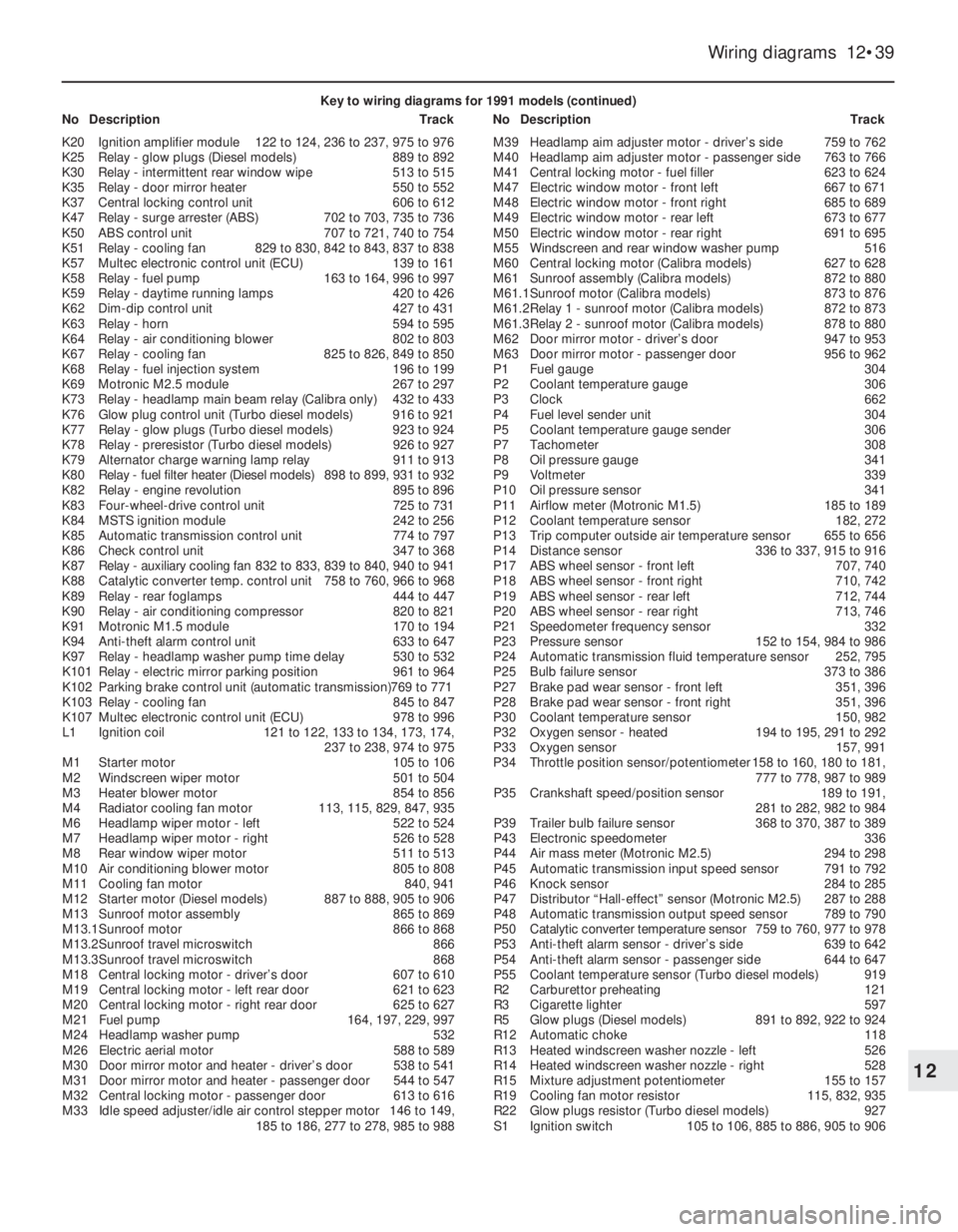
Wiring diagrams 12•39
12
Key to wiring diagrams for 1991 models (continued)
NoDescriptionTrackNoDescriptionTrack
K20Ignition amplifier module122 to 124, 236 to 237, 975 to 976
K25Relay - glow plugs (Diesel models)889 to 892
K30Relay - intermittent rear window wipe513 to 515
K35Relay - door mirror heater550 to 552
K37Central locking control unit606 to 612
K47Relay - surge arrester (ABS)702 to 703, 735 to 736
K50ABS control unit707 to 721, 740 to 754
K51Relay - cooling fan829 to 830, 842 to 843, 837 to 838
K57Multec electronic control unit (ECU)139 to 161
K58Relay - fuel pump163 to 164, 996 to 997
K59Relay - daytime running lamps420 to 426
K62Dim-dip control unit427 to 431
K63Relay - horn594 to 595
K64Relay - air conditioning blower802 to 803
K67Relay - cooling fan825 to 826, 849 to 850
K68Relay - fuel injection system196 to 199
K69Motronic M2.5 module267 to 297
K73Relay - headlamp main beam relay (Calibra only)432 to 433
K76Glow plug control unit (Turbo diesel models)916 to 921
K77Relay - glow plugs (Turbo diesel models)923 to 924
K78Relay - preresistor (Turbo diesel models)926 to 927
K79Alternator charge warning lamp relay911 to 913
K80Relay - fuel filter heater (Diesel models)898 to 899, 931 to 932
K82Relay - engine revolution895 to 896
K83Four-wheel-drive control unit725 to 731
K84MSTS ignition module242 to 256
K85Automatic transmission control unit774 to 797
K86Check control unit347 to 368
K87Relay - auxiliary cooling fan832 to 833, 839 to 840, 940 to 941
K88Catalytic converter temp. control unit758 to 760, 966 to 968
K89Relay - rear foglamps444 to 447
K90Relay - air conditioning compressor820 to 821
K91Motronic M1.5 module170 to 194
K94Anti-theft alarm control unit633 to 647
K97Relay - headlamp washer pump time delay530 to 532
K101Relay - electric mirror parking position961 to 964
K102Parking brake control unit (automatic transmission)769 to 771
K103Relay - cooling fan845 to 847
K107Multec electronic control unit (ECU)978 to 996
L1Ignition coil121 to 122, 133 to 134, 173, 174,
237 to 238, 974 to 975
M1Starter motor105 to 106
M2Windscreen wiper motor501 to 504
M3Heater blower motor854 to 856
M4Radiator cooling fan motor113, 115, 829, 847, 935
M6Headlamp wiper motor - left522 to 524
M7Headlamp wiper motor - right526 to 528
M8Rear window wiper motor511 to 513
M10Air conditioning blower motor805 to 808
M11Cooling fan motor840, 941
M12Starter motor (Diesel models)887 to 888, 905 to 906
M13Sunroof motor assembly865 to 869
M13.1Sunroof motor866 to 868
M13.2Sunroof travel microswitch866
M13.3Sunroof travel microswitch868
M18Central locking motor - driver’s door607 to 610
M19Central locking motor - left rear door621 to 623
M20Central locking motor - right rear door625 to 627
M21Fuel pump164, 197, 229, 997
M24Headlamp washer pump532
M26Electric aerial motor588 to 589
M30Door mirror motor and heater - driver’s door538 to 541
M31Door mirror motor and heater - passenger door544 to 547
M32Central locking motor - passenger door613 to 616
M33Idle speed adjuster/idle air control stepper motor146 to 149,
185 to 186, 277 to 278, 985 to 988M39Headlamp aim adjuster motor - driver’s side759 to 762
M40Headlamp aim adjuster motor - passenger side763 to 766
M41Central locking motor - fuel filler623 to 624
M47Electric window motor - front left667 to 671
M48Electric window motor - front right685 to 689
M49Electric window motor - rear left673 to 677
M50Electric window motor - rear right691 to 695
M55Windscreen and rear window washer pump516
M60Central locking motor (Calibra models)627 to 628
M61Sunroof assembly (Calibra models)872 to 880
M61.1Sunroof motor (Calibra models)873 to 876
M61.2Relay 1 - sunroof motor (Calibra models)872 to 873
M61.3Relay 2 - sunroof motor (Calibra models)878 to 880
M62Door mirror motor - driver’s door947 to 953
M63Door mirror motor - passenger door956 to 962
P1Fuel gauge304
P2Coolant temperature gauge306
P3Clock662
P4Fuel level sender unit304
P5Coolant temperature gauge sender306
P7Tachometer308
P8Oil pressure gauge341
P9Voltmeter339
P10Oil pressure sensor341
P11Airflow meter (Motronic M1.5)185 to 189
P12Coolant temperature sensor182, 272
P13Trip computer outside air temperature sensor655 to 656
P14Distance sensor336 to 337, 915 to 916
P17ABS wheel sensor - front left707, 740
P18ABS wheel sensor - front right710, 742
P19ABS wheel sensor - rear left712, 744
P20ABS wheel sensor - rear right713, 746
P21Speedometer frequency sensor332
P23Pressure sensor152 to 154, 984 to 986
P24Automatic transmission fluid temperature sensor252, 795
P25Bulb failure sensor373 to 386
P27Brake pad wear sensor - front left351, 396
P28Brake pad wear sensor - front right351, 396
P30Coolant temperature sensor150, 982
P32Oxygen sensor - heated194 to 195, 291 to 292
P33Oxygen sensor157, 991
P34Throttle position sensor/potentiometer158 to 160, 180 to 181,
777 to 778, 987 to 989
P35Crankshaft speed/position sensor189 to 191,
281 to 282, 982 to 984
P39Trailer bulb failure sensor368 to 370, 387 to 389
P43Electronic speedometer336
P44Air mass meter (Motronic M2.5)294 to 298
P45Automatic transmission input speed sensor791 to 792
P46Knock sensor284 to 285
P47Distributor “Hall-effect” sensor (Motronic M2.5)287 to 288
P48Automatic transmission output speed sensor789 to 790
P50Catalytic converter temperature sensor759 to 760, 977 to 978
P53Anti-theft alarm sensor - driver’s side639 to 642
P54Anti-theft alarm sensor - passenger side644 to 647
P55Coolant temperature sensor (Turbo diesel models)919
R2Carburettor preheating121
R3Cigarette lighter597
R5Glow plugs (Diesel models)891 to 892, 922 to 924
R12Automatic choke118
R13Heated windscreen washer nozzle - left526
R14Heated windscreen washer nozzle - right528
R15Mixture adjustment potentiometer155 to 157
R19Cooling fan motor resistor115, 832, 935
R22Glow plugs resistor (Turbo diesel models)927
S1Ignition switch105 to 106, 885 to 886, 905 to 906
Page 54 of 525

12•40Wiring diagrams
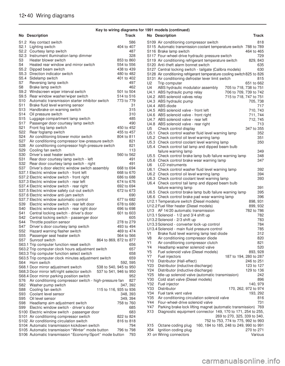
Key to wiring diagrams for 1991 models (continued)
NoDescriptionTrackNoDescriptionTrack
S1.2Key contact switch586
S2.1Lighting switch404 to 407
S2.2Courtesy lamp switch487
S2.3Instrument illumination lamp dimmer328
S3Heater blower switch853 to 860
S4Heated rear window and mirror switch554 to 556
S5.2Dipped beam switch438 to 439
S5.3Direction indicator switch480 to 482
S5.4Sidelamp switch401 to 402
S7Reversing lamp switch497
S8Brake lamp switch462
S9.2Windscreen wiper interval switch501 to 504
S9.5Rear window washer/wiper switch514 to 516
S10Automatic transmission starter inhibitor switch773 to 779
S11Brake fluid level warning sensor31
S13Handbrake-on warning switch315
S14Oil pressure switch310
S15Luggage compartment lamp switch485
S17Passenger door courtesy lamp switch490
S21Front fog lamp switch450 to 452
S22Rear foglamp switch455 to 457
S24Air conditioning blower motor switch804 to 811
S27Air conditioning compressor low-pressure switch821
S28Air conditioning compressor high-pressure switch821
S29Cooling fan switch113
S30Driver’s seat heater switch560 to 562
S31Rear door courtesy lamp switch - left491
S32Rear door courtesy lamp switch - right491
S37Driver’s door electric window switch assembly668 to 694
S37.1Electric window switch - front left668 to 670
S37.2Electric window switch - front right686 to 688
S37.3Electric window switch - rear left674 to 676
S37.4Electric window switch - rear right692 to 694
S37.5Electric window safety cut-out switch672 to 673
S37.6Electric window anti-jam switch690
S37.7Electric window automatic control677 to 682
S39Electric window switch - rear left door678 to 680
S40Electric window switch - rear right door696 to 698
S41Central locking switch - driver’s door601 to 603
S42Central locking switch - passenger door605
S44Throttle position sensor278 to 279
S47Driver’s door courtesy lamp switch493 to 494
S52Hazard warning flasher switch469 to 474
S55Passenger seat heater switch564 to 566
S57Sunroof switch864 to 869, 872 to 877
S63.1Trip computer function reset switch656
S63.2Trip computer clock hours adjustment switch657
S63.3Trip computer function select switch658
S63.5Trip computer clock minutes adjustment switch659
S64Horn switch592, 595
S68.1Door mirror adjustment switch538 to 540, 945 to 950
S68.3Door mirror left/right selector switch537 to 541, 946 to 950
S68.4Door mirror parking position switch952
S76Air conditioning compressor switch - high-pressure fan827
S82Washer pump switch347, 392
S88Cooling fan switch115 to 116, 935 to 936
S93Coolant level sensor348, 393
S95Oil level sensor349, 394
S98Headlamp aim adjustment switch758 to 760
S99Electric window switch - driver’s door685
S100Electric window switch - passenger door683
S101Air conditioning compressor switch822 to 824
S102Air conditioning circulation switch816 to 818
S104Automatic transmission kickdown switch794
S105Automatic transmission “Winter” mode button796 to 798
S106Automatic transmission “Economy/Sport” mode button793S109Air conditioning compressor switch818
S115Automatic transmission coolant temperature switch788 to 789
S116Brake lamp switch464 to 465
S117Four-wheel-drive hydraulic pressure switch729
S119Air conditioning refrigerant temperature switch829, 843
S120Anti-theft alarm bonnet switch635
S127Central locking switch - tailgate (Calibra models)630
S128Air conditioning refrigerant temperature cooling switch825 to 826
S131Air conditioning defroster lever limit switch815
U2Trip computer651 to 662
U4ABS hydraulic modulator assembly705 to 718, 738 to 751
U4.1ABS hydraulic pump relay706 to 709, 739 to 742
U4.2ABS solenoid valves relay715 to 718, 747 to 751
U4.3ABS hydraulic pump705, 738
U4.4ABS diode717
U4.5ABS solenoid valve - front left710, 743
U4.6ABS solenoid valve - front right711, 744
U4.7ABS solenoid valve - rear left712, 745
U4.8ABS solenoid valve - rear right713
U5Check control display347 to 355
U5.1Check control washer fluid level warning lamp352
U5.2Check control oil level warning lamp351
U5.3Check control coolant level warning lamp350
U5.4Check control tail lamp and dipped beam bulb
failure warning lamp349
U5.5Check control brake lamp bulb failure warning lamp348
U5.6Check control brake wear warning lamp347
U6LCD instruments
U6.1Check control washer fluid level warning lamp392
U6.2Check control oil level warning lamp394
U6.3Check control coolant level warning lamp393
U6.4Check control tail lamp and dipped beam bulb
failure warning lamp391
U6.5Check control brake lamp bulb failure warning lamp395
U6.6Check control brake pad wear warning lamp396
U12.1Temperature switch (Diesel models)898, 931
U12.2Fuel filter heater (Diesel models)899, 932
U13AF14/20automatic transmission782 to 786
U13.1Solenoid - 1/2 and 3/4 shift up782
U13.2Solenoid - 2/3 shift up783
U13.3Solenoid - converter lock-up control784
U13.4Solenoid - main fluid pressure control785
V1Brake fluid level warning lamp test diode312
V8Air conditioning compressor diode820
Y1Air conditioning compressor clutch821
Y4Headlamp washer solenoid valve520
Y5Fuel solenoid valve (Diesel models)893, 928
Y7Fuel injectors187 to 194, 280 to 287
Y10Distributor (Hall-effect)246 to 251
Y23Distributor (inductive discharge)123 to 127
Y24Distributor (inductive discharge)129 to 136
Y25Idle-up solenoid valve (automatic transmission)242
Y30Cold start valve (Diesel models)896
Y32Fuel injector140, 979
Y33Distributor170, 262, 972 to 974
Y34Fuel tank vent valve193, 292
Y35Air conditioning circulation solenoid valve816
Y44Four-wheel-drive solenoid valve731
Y47Parking brake lock lifting magnet (automatic transmission)769
X13Diagnostic equipment connector149, 170 to 171, 254 to 255,
269 to 270, 325, 339 to 340,
752 to 753, 774 to 775, 992 to 993
X15Octane coding plug160, 184 to 185, 248 to 249, 990 to 991
X54Ignition coding plug270 to 271
X1 onWiring connectorsVarious
Page 120 of 525

Refitting
11Refitting is a reversal of removal, but
make sure that the column switch gaiters
engage in the cut-outs in the upper shroud.
Instrument panel lower trim
panel
Removal
12Remove the steering column shrouds, as
described previously in this Section.
13The panel is secured by clips at either
end, which must be released by pulling the
ends of the panel from the facia (see
illustration). This is a tricky operation, as to
release both ends, the panel must be bent
slightly at its centre. Take great care, as the
panel is easily broken.
Refitting
14Refitting is a reversal of removal.
Instrument panel upper trim
panel
Removal
15Remove the instrument panel lower trim
panel, as described previously in this Section.
16Extract the two now-exposed lower trim
panel securing screws, one from each end of
the panel, noting that the left-hand screw also
secures the heater control panel (see
illustration).
17Withdraw the panel from the facia (see
illustration).
Refitting
18Refitting is a reversal of removal.
Lighting switch panel
Removal
19Remove the instrument panel upper and
lower trim panels, as described previously in
this Section.
20Remove the remaining securing screw
from the left-hand side of the lighting switch
panel (see illustration).
21Pull the lighting switch panel from the
facia, to release the securing clips at the
right-hand end.
22Ensure that the battery negative lead has
been disconnected, then disconnect the
wiring plugs from the switches, and withdraw
the switch panel (see illustration).
Refitting
23Refitting is a reversal of removal.
Radio/oddments tray panel
Removal
24Remove the radio, as described in
Chapter 12.
25Remove the lower and upper instrument
panel trim panels, as described previously in
this Section.
26Remove the lower securing screw from
the right-hand side of the heater control
panel.
27Remove the clock or trip computer, as
applicable, from the facia referring to Chapter
12, if necessary.
28Remove the two now-exposed heater
control panel securing screws from the
clock/trip computer aperture.
29Carefully manipulate the heater control
panel forwards within the limits of the control
cable travel, then manipulate the
radio/oddments tray out from the facia. This is
a tricky operation, as the radio/oddments tray
securing lugs rest behind the heater control
panel securing lugs (see illustrations). Take
care not to strain the heater control cables.
30With the radio/oddments tray removed,
the radio support tray can be removed if
desired by unscrewing the two securing
screws, then sliding the tray forwards to
disconnect the wiring and aerial plugs (see
illustrations).
Refitting
31Refitting is a reversal of removal, taking
care not to damage the heater control
components as the radio/oddments tray is
manipulated into position.
Bodywork and fittings 11•17
37.17 Withdrawing the instrument panel
upper trim panel
37.29B Manipulating the radio/oddments
tray from the facia37.29A Right-hand securing lug (arrowed)
behind heater control panel37.22 Disconnecting the wiring plugs from
the lighting switches
37.20 Removing the lower left-hand
lighting switch panel securing screw
37.16 Unscrewing the left-hand instrument
panel upper trim panel securing screw37.13 Removing the instrument panel
lower trim panel
11
Page 122 of 525

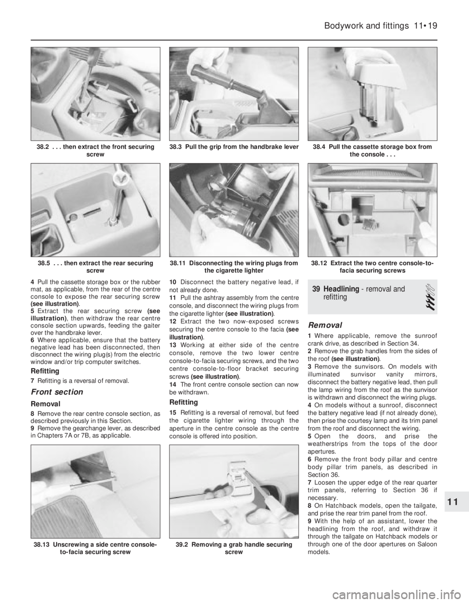
4Pull the cassette storage box or the rubber
mat, as applicable, from the rear of the centre
console to expose the rear securing screw
(see illustration).
5Extract the rear securing screw (see
illustration), then withdraw the rear centre
console section upwards, feeding the gaiter
over the handbrake lever.
6Where applicable, ensure that the battery
negative lead has been disconnected, then
disconnect the wiring plug(s) from the electric
window and/or trip computer switches.
Refitting
7Refitting is a reversal of removal.
Front section
Removal
8Remove the rear centre console section, as
described previously in this Section.
9Remove the gearchange lever, as described
in Chapters 7A or 7B, as applicable. 10Disconnect the battery negative lead, if
not already done.
11Pull the ashtray assembly from the centre
console, and disconnect the wiring plugs from
the cigarette lighter (see illustration).
12Extract the two now-exposed screws
securing the centre console to the facia (see
illustration).
13Working at either side of the centre
console, remove the two lower centre
console-to-facia securing screws, and the two
centre console-to-floor bracket securing
screws (see illustration).
14The front centre console section can now
be withdrawn.
Refitting
15Refitting is a reversal of removal, but feed
the cigarette lighter wiring through the
aperture in the centre console as the centre
console is offered into position.
39Headlining -removal and
refitting
3
Removal
1Where applicable, remove the sunroof
crank drive, as described in Section 34.
2Remove the grab handles from the sides of
the roof (see illustration).
3Remove the sunvisors. On models with
illuminated sunvisor vanity mirrors,
disconnect the battery negative lead, then pull
the lamp wiring from the roof as the sunvisor
is withdrawn and disconnect the wiring plugs.
4On models without a sunroof, disconnect
the battery negative lead (if not already done),
then prise the courtesy lamp and its trim panel
from the roof and disconnect the wiring.
5Open the doors, and prise the
weatherstrips from the tops of the door
apertures.
6Remove the front body pillar and centre
body pillar trim panels, as described in
Section 36.
7Loosen the upper edge of the rear quarter
trim panels, referring to Section 36 if
necessary.
8On Hatchback models, open the tailgate,
and prise the rear trim panel from the roof.
9With the help of an assistant, lower the
headlining from the roof, and withdraw it
through the tailgate on Hatchback models or
through one of the door apertures on Saloon
models.
Bodywork and fittings 11•19
38.4 Pull the cassette storage box from
the console . . .
38.12 Extract the two centre console-to-
facia securing screws38.11 Disconnecting the wiring plugs from
the cigarette lighter
38.3 Pull the grip from the handbrake lever38.2 . . . then extract the front securing
screw
11
38.5 . . . then extract the rear securing
screw
38.13 Unscrewing a side centre console-
to-facia securing screw39.2 Removing a grab handle securing
screw
Page 237 of 525

4Position a container beneath the tank, then
disconnect the bottom hose and allow the
contents of the tank to drain into the
container. Suspend the bottom hose as high
as possible above the engine to prevent
coolant loss.
Refitting
5Refitting is a reversal of removal, but on
completion check and if necessary top-up the
coolant level, as described in Section 4. The
coolant drained from the expansion tank
during removal can be re-used, provided it
has not been contaminated.
Coolant level sensor
6The coolant level sensor, where fitted, is an
integral part of the expansion tank cap. If the
level sensor is faulty, the complete cap
assembly must be renewed.
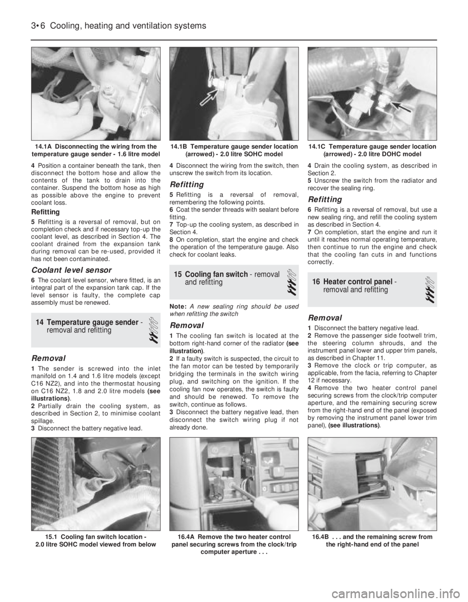
14Temperature gauge sender -
removal and refitting
2
Removal
1The sender is screwed into the inlet
manifold on 1.4 and 1.6 litre models (except
C16 NZ2), and into the thermostat housing
on C16 NZ2, 1.8 and 2.0 litre models (see
illustrations).
2Partially drain the cooling system, as
described in Section 2, to minimise coolant
spillage.
3Disconnect the battery negative lead.4Disconnect the wiring from the switch, then
unscrew the switch from its location.
Refitting
5Refitting is a reversal of removal,
remembering the following points.
6Coat the sender threads with sealant before
fitting.
7Top-up the cooling system, as described in
Section 4.
8On completion, start the engine and check
the operation of the temperature gauge. Also
check for coolant leaks.
15Cooling fan switch -removal
and refitting
3
Note: A new sealing ring should be used
when refitting the switch
Removal
1The cooling fan switch is located at the
bottom right-hand corner of the radiator (see
illustration).
2If a faulty switch is suspected, the circuit to
the fan motor can be tested by temporarily
bridging the terminals in the switch wiring
plug, and switching on the ignition. If the
cooling fan now operates, the switch is faulty
and should be renewed. To remove the
switch, continue as follows.
3Disconnect the battery negative lead, then
disconnect the switch wiring plug if not
already done.4Drain the cooling system, as described in
Section 2.
5Unscrew the switch from the radiator and
recover the sealing ring.
Refitting
6Refitting is a reversal of removal, but use a
new sealing ring, and refill the cooling system
as described in Section 4.
7On completion, start the engine and run it
until it reaches normal operating temperature,
then continue to run the engine and check
that the cooling fan cuts in and functions
correctly.
16Heater control panel -
removal and refitting
3
Removal
1Disconnect the battery negative lead.
2Remove the passenger side footwell trim,
the steering column shrouds, and the
instrument panel lower and upper trim panels,
as described in Chapter 11.
3Remove the clock or trip computer, as
applicable, from the facia, referring to Chapter
12 if necessary.
4Remove the two heater control panel
securing screws from the clock/trip computer
aperture, and the remaining securing screw
from the right-hand end of the panel (exposed
by removing the instrument panel lower trim
panel), (see illustrations).
3•6Cooling, heating and ventilation systems
14.1A Disconnecting the wiring from the
temperature gauge sender - 1.6 litre model14.1C Temperature gauge sender location
(arrowed) - 2.0 litre DOHC model
16.4B . . . and the remaining screw from
the right-hand end of the panel16.4A Remove the two heater control
panel securing screws from the clock/trip
computer aperture . . .15.1 Cooling fan switch location -
2.0 litre SOHC model viewed from below
14.1B Temperature gauge sender location
(arrowed) - 2.0 litre SOHC model
Page 261 of 525

REF•22Glossary of Technical Terms
EEGR valveA valve used to introduce exhaust
gases into the intake air stream.
Electronic control unit (ECU)A computer
which controls (for instance) ignition and fuel
injection systems, or an anti-lock braking
system. For more information refer to the
Haynes Automotive Electrical and Electronic
Systems Manual.
Electronic Fuel Injection (EFI)A computer
controlled fuel system that distributes fuel
through an injector located in each intake port
of the engine.
Emergency brakeA braking system,
independent of the main hydraulic system,
that can be used to slow or stop the vehicle if
the primary brakes fail, or to hold the vehicle
stationary even though the brake pedal isn’t
depressed. It usually consists of a hand lever
that actuates either front or rear brakes
mechanically through a series of cables and
linkages. Also known as a handbrake or
parking brake.
EndfloatThe amount of lengthwise
movement between two parts. As applied to a
crankshaft, the distance that the crankshaft
can move forward and back in the cylinder
block.
Engine management system (EMS)A
computer controlled system which manages
the fuel injection and the ignition systems in
an integrated fashion.
Exhaust manifoldA part with several
passages through which exhaust gases leave
the engine combustion chambers and enter
the exhaust pipe.
FFan clutchA viscous (fluid) drive coupling
device which permits variable engine fan
speeds in relation to engine speeds.Feeler bladeA thin strip or blade of hardened
steel, ground to an exact thickness, used to
check or measure clearances between parts.
Firing orderThe order in which the engine
cylinders fire, or deliver their power strokes,
beginning with the number one cylinder.
Flywheel A heavy spinning wheel in which
energy is absorbed and stored by means of
momentum. On cars, the flywheel is attached
to the crankshaft to smooth out firing
impulses.
Free playThe amount of travel before any
action takes place. The “looseness” in a
linkage, or an assembly of parts, between the
initial application of force and actual
movement. For example, the distance the
brake pedal moves before the pistons in the
master cylinder are actuated.
FuseAn electrical device which protects a
circuit against accidental overload. The typical
fuse contains a soft piece of metal which is
calibrated to melt at a predetermined current
flow (expressed as amps) and break the
circuit.
Fusible linkA circuit protection device
consisting of a conductor surrounded by
heat-resistant insulation. The conductor is
smaller than the wire it protects, so it acts as
the weakest link in the circuit. Unlike a blown
fuse, a failed fusible link must frequently be
cut from the wire for replacement.
GGapThe distance the spark must travel in
jumping from the centre electrode to the sideelectrode in a spark plug. Also refers to the
spacing between the points in a contact
breaker assembly in a conventional points-
type ignition, or to the distance between the
reluctor or rotor and the pickup coil in an
electronic ignition.
GasketAny thin, soft material - usually cork,
cardboard, asbestos or soft metal - installed
between two metal surfaces to ensure a good
seal. For instance, the cylinder head gasket
seals the joint between the block and the
cylinder head.
GaugeAn instrument panel display used to
monitor engine conditions. A gauge with a
movable pointer on a dial or a fixed scale is an
analogue gauge. A gauge with a numerical
readout is called a digital gauge.
HHalfshaftA rotating shaft that transmits
power from the final drive unit to a drive
wheel, usually when referring to a live rear
axle.
Harmonic balancerA device designed to
reduce torsion or twisting vibration in the
crankshaft. May be incorporated in the
crankshaft pulley. Also known as a vibration
damper.
HoneAn abrasive tool for correcting small
irregularities or differences in diameter in an
engine cylinder, brake cylinder, etc.
Hydraulic tappetA tappet that utilises
hydraulic pressure from the engine’s
lubrication system to maintain zero clearance
(constant contact with both camshaft and
valve stem). Automatically adjusts to variation
in valve stem length. Hydraulic tappets also
reduce valve noise.
IIgnition timingThe moment at which the
spark plug fires, usually expressed in the
number of crankshaft degrees before the
piston reaches the top of its stroke.
Inlet manifoldA tube or housing with
passages through which flows the air-fuel
mixture (carburettor vehicles and vehicles with
throttle body injection) or air only (port fuel-
injected vehicles) to the port openings in the
cylinder head.
Exhaust manifold
Feeler blade
Adjusting spark plug gap
Gasket
EGR valve