Page 1348 of 1378

WHEEL A LIG NM EN T S PEC IF IC ATIO NS & P R O CED URES
�
1988 J e ep C hero ke e
1988 Wheel Alignment
INTRODUCTION
PRE-ALIGNMENT
VEHICLE CHECKS
Prior to making wheel alignment adjustments, check and
adjust the following items:
1) Tire pressure must be inflated to manufacturers
recommended specifications.Tires should be equal in size and type.
Runout must not be excessive. Tires and wheels should be in balance.
2) Wheel bearings must be properly adjusted. Steering
linkage and suspension must not have excessive wear and/or looseness.
Check for wear in tie rod ends and ball joints.
3) Steering gear box must not have excessive play. Check and
adjust to manufacturer's specifications.
4) Vehicle must be at correct ride height with full fuel
load and spare tire in vehicle. No extra load should be on vehicle.
5) Vehicle must be level with floor and with suspension
settled. Jounce front and rear of vehicle several times and allow it
to settle to normal ride height.
6) Ensure steering wheel spokes are centered with front
wheels in straight-ahead position, correct by shortening one tie rod
adjusting sleeve and lengthening opposite sleeve equal amounts.
7) Ensure wheel lug nuts are tightened to torque
specifications.
DESCRIPTION
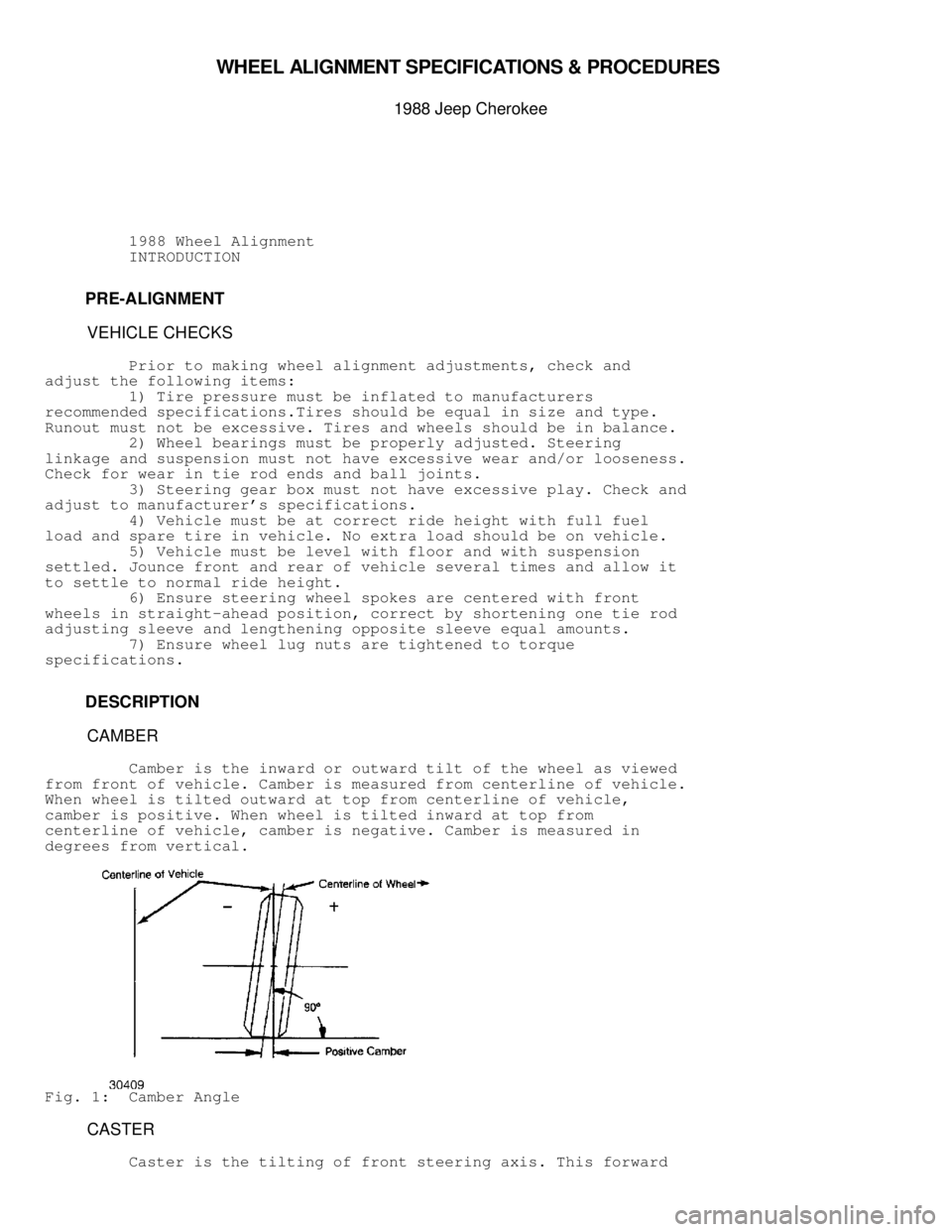
CAMBER
Camber is the inward or outward tilt of the wheel as viewed
from front of vehicle. Camber is measured from centerline of vehicle.
When wheel is tilted outward at top from centerline of vehicle,
camber is positive. When wheel is tilted inward at top from
centerline of vehicle, camber is negative. Camber is measured in
degrees from vertical.
Fig. 1: Camber Angle
CASTER
Caster is the tilting of front steering axis. This forward
Page 1349 of 1378
or backward tilt from vertical is viewed from side of vehicle. When
axis is tilted backward from vertical, caster is said to be positive,
creating a trailing action on front wheels. When axis is tilted
forward, caster is negative, causing a leading action on front wheels.
Fig. 2: Caster Angle
TOE
Toe is the measured difference in inches of distance between
the front edge of the tires and the rear edge of the tires at spindle
height. Toe can be measured in inches or degrees.
ADJUSTMENT
TOE
1) Measure toe with front wheels straight-ahead and steering
wheel locked in a centered position. Adjust toe by loosening clamps
and adjusting sleeve or adjusting ends on right and left tie rods
equally and in opposite directions to maintain steering wheel in
centered position.
2) If steering wheel is not centered to begin with,
determine which tire assembly is toed in or out more than the other
Page 1353 of 1378

ALIGNMENT SPECIFICATIONS
WHEEL ALIGNMENT SPECIFICATIONS TABLE������������������\
������������������\
������������������\
������������������\
������������������\
������������������\
�����������
Application Specification
Cherokee, Comanche,
Wrangler & Wagoneer
Ride Height in Inches ........................... .....
Adjustment Procedures ........................... .....
Camber in Degrees (Fraction) .............. -1/2 to 1/2
Camber in Degrees (Decimal) ............. -0.50 to 0.50
Caster in Degrees (Fraction) ................... 7 to 8
Caster in Degrees (Decimal) ................ 7.0 to 8.0
Toe-In in Inches (Fraction) .............. 1/32 to 1/32
Toe-In in Inches (Decimal) ............. 0.031 to 0.031
Toe-In in Degrees (Fraction) ............. 1/16 to 1/16
Toe-In in Degrees (Decimal) ............ 0.063 to 0.063
Toe-Out on Turns
Inner .......................................... NS
Outer .......................................... NS
Steering Axis Inclination (SAI) ................ 8 1/2
�
Grand Wagoneer
Ride Height in Inches ........................... .....
Adjustment Procedures ........................... .....
Camber in Degrees (Fraction)................... 0 to 1/2
Camber in Degrees (Decimal) .................. 0 to 0.5
Caster in Degrees (Fraction) ................... 4 to 5
Caster in Degrees (Decimal) ................ 4.0 to 5.0
Toe-In in Inches (Fraction) .............. 3/64 to 3/32
Toe-In in Inches (Decimal) ............. 0.047 to 0.094
Toe-In in Degrees (Fraction) ............. 3/32 to 3/16
Toe-In in Degrees (Decimal) ............ 0.094 to 0.188
Toe-Out on Turns
Inner .......................................... NS
Outer .......................................... NS
Steering Axis Inclination (SAI) ................ 8 1/2
�
NS - Information not available from manufacturer.������������������\
������������������\
������������������\
������������������\
������������������\
������������������\
���������
RIDING HEIGHT SPECIFICATIONS
Inflate tires to proper air pressure. Specifications can be
found on door pillar or in glove box. Cargo compartment must by
empty. Fuel tank should be full. Bounce vehicle up and down to
normalize ride height. Ride height specifications in regard to setting
camber and caster are not provided by the manufacturer.
Page 1357 of 1378

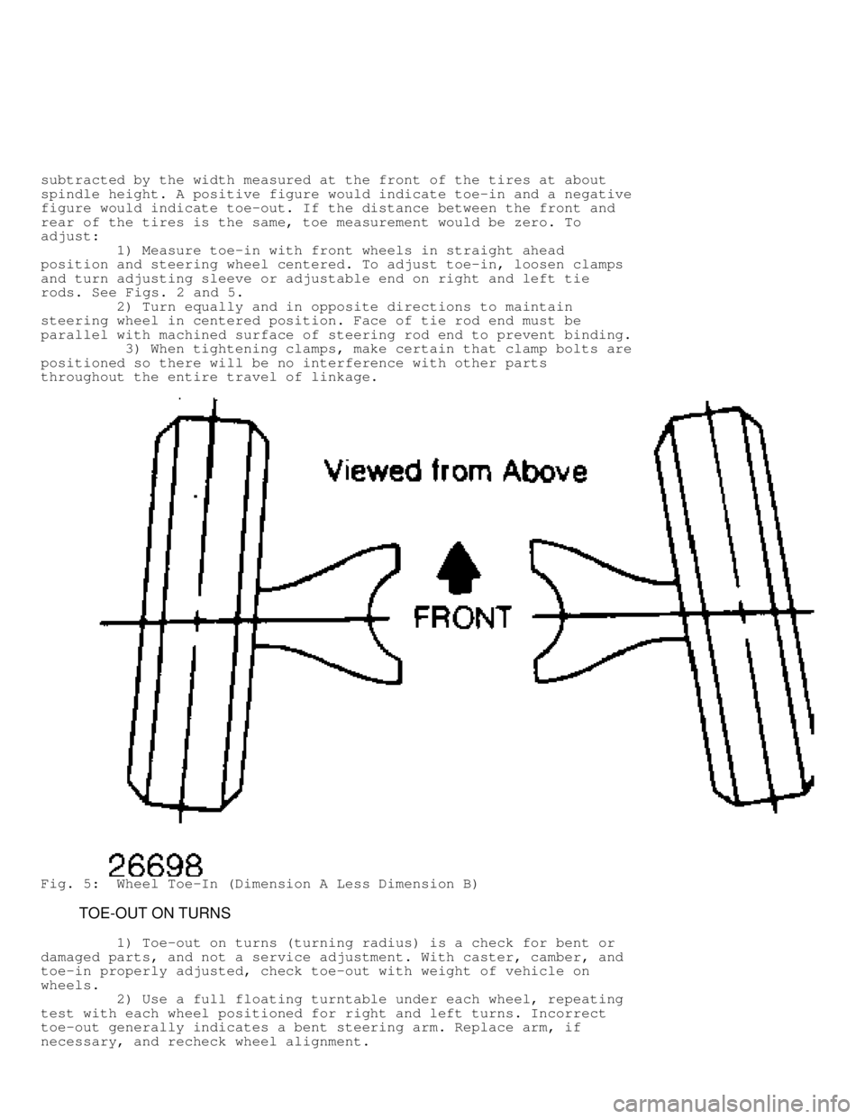
subtracted by the width measured at the front of the tires at about
spindle height. A positive figure would indicate toe-in and a negative
figure would indicate toe-out. If the distance between the front and
rear of the tires is the same, toe measurement would be zero. To
adjust:
1) Measure toe-in with front wheels in straight ahead
position and steering wheel centered. To adjust toe-in, loosen clamps
and turn adjusting sleeve or adjustable end on right and left tie
rods. See Figs. 2 and 5.
2) Turn equally and in opposite directions to maintain
steering wheel in centered position. Face of tie rod end must be
parallel with machined surface of steering rod end to prevent binding.
3) When tightening clamps, make certain that clamp bolts are
positioned so there will be no interference with other parts
throughout the entire travel of linkage.
Fig. 5: Wheel Toe-In (Dimension A Less Dimension B)
TOE-OUT ON TURNS
1) Toe-out on turns (turning radius) is a check for bent or
damaged parts, and not a service adjustment. With caster, camber, and
toe-in properly adjusted, check toe-out with weight of vehicle on
wheels.
2) Use a full floating turntable under each wheel, repeating
test with each wheel positioned for right and left turns. Incorrect
toe-out generally indicates a bent steering arm. Replace arm, if
necessary, and recheck wheel alignment.