1988 FIAT TEMPRA wheel
[x] Cancel search: wheelPage 96 of 171

• Step 4: Refill the gearbox with the correct grade and
quantity of FL oil. See Chapter
3,
Facts and Figures.
Section as appropriate, for the replacement of the rear
crankshaft seal. B
—1 Step 5: When the brake calipers have been refitted,
pump the brake pedal until its normal solid feel is restored.
• Step 6: Use a self-grip wrench to reconnect the gear rod
balls and sockets. Use new drive-shaft nuts, tightened to the
correct torque and staked into the shaft grooves with a
punch. See Job 9.
Job 3. Clutch - replacement.
1 - cover plate 2 - driven plate 3 - release bearing
4 - retaining bolt 5 - spring washer
;
Job 3-1
Q Step 1: These first three numbered parts are the parts
you will need to obtain, from your FIAT dealership.
FACT FILE: CLUTCH COMPONENTS
• We strongly recommend that all three
main components: clutch cover, driven
plate and release bearing are replaced
after a high mileage, ensuring longer life
and smoother operation.
• If one is worn, they are all likely to be, so save
yourself another big stripdown in the near future!
LI Step 2: Remove the transmission. See Job 1.
• Step 3: Unscrew the clutch cover bolts (see illustration
Job
3-1,
part 4) progressively until the spring pressure is
released, then remove the bolts. Ease the cover (part 1) off its
dowels and catch the driven plate {part 2) as it falls.
• Step 6: Check the surface of the flywheel that mates
with the clutch, for scoring, or significant micro cracking
caused by excessive head generated by clutch slip. Replace the
flywheel if in doubt.
7ZJ
• Step 7: Check the
release fork pivot, inside
the bellhousing, for wear
Replace the bushes (see
inset) if necessary, lubri-
cating with a small
quantity of molybdenum
disulphide grease.
• Step 8: Replace the bush
(a) by removing the circlip (b)
from the lever shaft (d). Note
the position of the arm (c) on
the splines for refitting and
slide it off. Prise the bush out
using a screwdriver. Lubricate
the new bush with a small
quantity of molybdenum disul-
phide grease and install. Refit
the arm to the fork control
shaft (d) with a new circlip.
Refit the release bearing (e).
• Step 9: Clean any oil (or the protective film) from the
clutch cover and flywheel faces.
• Step 10: Offer the driven plate to the flywheel with the
side having the greatest hub projection facing outwards.
• Step 11: Locate the clutch cover on the flywheel dowels
and screw in the fixing bolts finger tight.
• Step 12: Use an aligning tool to make sure that the
clutch is centralised, otherwise the gearbox will not relocate
on the engine and damage can be caused to the centre plate.
B INSIDE INFORMATION: There is no spigot bush or
bearing in the crankshaft end, but there is an inden-
tation which you can 'feel' with a normal clutch
alignment tool allowing you to centralise the driven
plate between the clutch cover release fingers. B
• Step 5: B INSIDE
INFORMATION: Check
the inside of the
clutch bellhousing for
contamination by oil.
This indicates a leak
from either the
crankshaft rear seal
or the gearbox input
shaft seal (illus-
trated). A faulty seal should be replaced without delay.
Oil can cause judder and slip. Here, the seal (inset) is
being replaced. See PART A: ENGINE, Job 21 for the
position of the rear crankshaft seal. B
• Step 4: B INSIDE
INFORMATION! Check
the inside of the clutch
bell housing for conta-
mination by oil. This
indicates a leak from
either the crankshaft
rear seal or the
gearbox input shaft
seal. Oil can cause
judder and slip.
Replace the gearbox seal by removing the screws holding
in the thrust bearing sleeve (a), prising out the old and
fitting a new seal (b). See PART A: Petrol or Diesel
Page 98 of 171

Job 8. Automatic gear selector
control cable - replacement.
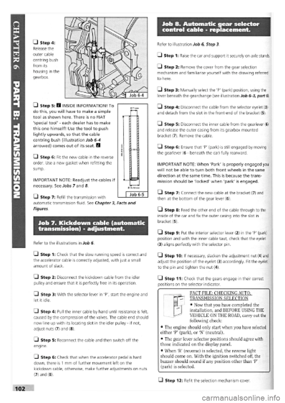
• Step 4:
Release the
outer cable
centring bush
from its
housing in the
gearbox.
• Step 5: H INSIDE INFORMATION! To
do this, you will have to make a simple
tool as shown here. There is no FIAT
'special tool'
-
each dealer has to make
this one himself! Use the tool to push
lightly upwards, so that the cable
centring bush (illustration Job
6-4
arrowed) comes out of its seat. B
• Step 6: Fit the new cable in the reverse
order. Use a new gasket when refitting the
sump.
IMPORTANT NOTE: Readjust the cables if
necessary. See Jobs 7 and 8.
Q Step 7: Refill the transmission with
automatic transmission fluid. See Chapter
3,
Facts and
Figures.
Job 7. Kickdown cable (automatic
transmission) - adjustment.
Refer to the illustrations in Job 6.
Q Step 1: Check that the slow running speed is correct and
the accelerator cable is correctly adjusted, with just a small
amount of slack.
Q Step 2: Disconnect the kickdown cable from the idler
pulley and ensure that it is perfectly free in its operation.
• Step 3: With the selector lever in 'P', start the engine and
let it idle.
Q Step 4: Pull the inner cable by hand until resistance is felt,
caused by the compression of the valves. The cable end should
now line up with its locating slot in the idler pulley
-
if not,
adjust nuts (7) and (8).
[_l Step 5: Reconnect the cable and then switch off the
engine.
• Step 6: Check that when the accelerator pedal is hard
down, there is
1
mm of further movement left on the
kickdown cable, otherwise, make further adjustments on nuts
(7) and (8).
Refer to illustration Job 6, Step 3.
• Step 1: Raise the car and support it securely on axle stands.
• Step 2: Remove the cover from the gear selection
mechanism and familiarise yourself with the drawing referred
to here.
Q Step 3: Manually select the 'P' (park) position, using the
lever beneath the gearchange (see illustration Job
6-3,
part
6).
• Step 4: Disconnect the cable from the selector eyelet (3)
and detach from the slot in the front end of the bracket (5).
Q Step 5: Disconnect the inner cable from the gearlever (6)
and release the outer casing from its gearbox mounted
bracket (7). Remove the cable.
Q Step 6: Ensure that 'P' (park) is still engaged by moving
the gearlever (6
-
beneath the car) fully rearward.
IMPORTANT NOTE: When 'Park' is properly engaged you
will not be able to turn both front wheels in the same
direction at the same time. This is because the trans-
mission should be 'locked' when 'park' is engaged.
• Step 7: Connect the new cable at the bracket (7) and
then at the bottom of the gear lever (6).
• Step 8: Feed the other end of the cable through to the
inside of the car and fix the outer casing into the slot in
bracket (5).
• Step 9: Put the interior selector lever (2) in the 'P' (park)
position and with the inner cable taut, check that the eyelet
(3) aligns perfectly with the selector pin.
• Step 10: If necessary, slacken the adjustment nut (4) and
adjust the position of the eyelet (3) accordingly. Fit the eyelet
to the pin and tighten the nut (4).
• Step 11: Check that the gears engage in their correct
positions on the selector indicator.
T "I FACT FILE: CHECKING AUTOT
qp- TRANSMISSION SELECTION
EL
-
• Now that you have completed the
installation, and BEFORE USING THE
VEHICLE ON THE ROAD, carry out the
following check:
• The engine should only start when you have selected
either 'P' (park), or 'N' (neutral).
• The gear lever selector positions should agree with
those indicated on the display panel.
• When 'R' (reverse) is selected, the reverse light
should come on. With the ignition switched off, the
buzzer should sound if any position other than 'P'
(park) is selected.
Q Step 12: Refit the selection mechanism cover.
0
Job 6-5
Page 99 of 171

Job 9. Drive-shaft - removal
and refitting.
IMPORTANT NOTE: For removal of the diesel Turbo's
drive-shaft, see also PART A: ENGINE, Job 18, Step 16A.
G Step 1: Drain the transmission oil.
• Step 8B: Diesel turbo
models have a bolt-on inboard
flange.
• Step 9: Withdraw the shaft
from the transmission (illus-
tration Job
9-8A,
part b).
G Step 2: Ask a helper to apply the footbrake very firmly
while
you
slacken the drive-shaft-to-hub nut, using a long bar
for
good
leverage after
opening out the
staking on the nut, as
far
as
possible. DON'T
do so
with the car off
the
ground because
the
very large force
needed could pull it off
its stands.
Remove the
nut
after the car has
been raised.
Job 10. Drive-shaft (outer)
constant velocity joint -
G Step 8A: Undo the
inboard
gaiter retaining
clip
(a) and release the
gaiter.
• Step 11: Refill the
transmission with oil.
See Chapter
3,
Facts
and Figures.
G Step 3: Slacken the hub nuts on the side to be worked
on.
Jack up the front of the car and support on axle stands.
Remove the roadwheel.
G Step 6: Remove the
hub
carrier securing
bolts
(arrowed) from the
base
of the front
suspension strut and tap
the
carrier down and out
of the
clamp. Pull the
top
outwards.
G Step 7: Push
or tap
the drive-
shaft
splines
(arrowed) out of
the hub
carrier,
taking
care not to
damage
the
thread.
Q Step 1: Remove the drive-shaft from the car. See Job 9. G Step 4: Unbolt the
brake hose support clip
from
the suspension strut.
G Step 5: Disconnect the
track rod end from the
steering arm using a
suitable splitter tool.
• Step 2: Remove
the gaiter retaining
clip...
Q Step 3: ...and pull
the gaiter clear.
• Step 4: Remove
the circlip and pull the
CV joint from the shaft.
Q Step 5: Thoroughly clean the joint with petrol or other
agent and dry. Check that the balls and their seats are still in a
good, unbroken shiny condition
-
no score marks. Fit a new
joint if in doubt.
• Step 6: Fit the new gaiter onto the shaft, followed by the
CV joint and circlip. Pack the joint with the grease supplied or
with FL Tutela MRM2 grease.
Q Step 7: Pull the gaiter over the joint and secure with the
retaining band or new screw-type clip. The drive-shaft
assembly is now ready for refitting.
• Step 10: Refit in the
reverse order, using a new
drive-shaft nut tightened to the
specified torque. See
Chapter
3,
Facts and
Figures Stake the nut
into the drive shaft
groove, as shown.
Page 121 of 171

s • F°r thenext tw° 5tep,s y°u
" (/ will require special tools
No.
1860765000
and No.
1842128000
to lock the sprocket and then remove it. If
you cannot hire these from your FIAT dealer you will
have
to adapt existing tools that will function correctly
and
not
cause
damage. Otherwise, have your properly
equipped
FIAT dealer carry out the work for you.
• Step 11: Using
the
special tool, lock
the
sprocket and
remove its fixing nut
(arrowed).
• Step 12: Using
the second
special
tool, extract the
sprocket (arrowed)
from
the pump
shaft.
• Step 13: Undo
the
pump retaining
bracket bolt
(arrowed)...
• Step 14: ...and
the Allen
screw
(arrowed), fixing the
pump
to the
mounting.
Job 16-11
• Step 20: Align the camshaft gear timing mark with that
on the timing belt rear cover (arrowed)...
• Step 15:
Remove the bolts (1
and 2)
-
pump to
front retaining
bracket. Remove the
pump.
• Step 19: Make
sure the crankshaft
pulley reference
marks are perfectly
aligned.
• Step 17: Refit the pump in the reverse order of removal.
Reset the timing as detailed in Step 18 onwards.
• Step 18: Align
the timing mark on
the pump sprocket
with the reference
mark on the rear
cover (arrowed).
Lock the sprocket in
position with special
tool no.
1842128000.
• Step 16: Q
INSIDE INFOR-
MATION: Remove
the rear mounting
bracket for use on
the new pump, if the pump is being replaced. E3
Q Step 21: ...and also check that the timing mark on the
bell housing aligns with the mark on the flywheel (arrowed).
Page 123 of 171

• Step A2: Start the engine and run until fluid emerges
from the loose injector fitting.
G Step A3: Keep the engine running and tighten the four
injector fittings.
B INSIDE INFORMATION: If the engine will not start,
check all fuel inlet pipe union points (see illustration Job
18-A1,
part D) and also the pipe fittings (Job 18-A1,
part E). Replace seal washers to eliminate the possibility
of air leaks. H
PART B: BLEEDING WATER FROM DIESEL
Bleed off water from the fuel filter as follows:
• Step B1: Unscrew the water bleed screw (Job 18-A1,
part B) under the filter.
• Step B2: Unscrew air bleed screw (Job 18-A1, part Q
above the filter.
• Step B3: Let water and fuel emerge until no more water
is present, then tighten, firstly the water bleed screw (B) under
filter, and then the air bleed screw (C) above the filter.
PART G: STEERING AND SUSPENSION
PART G: Contents
Job
1.
The systems explained.
Job
2.
Steering wheel
-
removal and refitting
Job 3. Track rod end balijoint
-
replacement.
Job
4.
Steering rack gaiter
-
replacement.
Job 5. Steering rack
-
replacement.
Job
6.
Power steering pump
-
removal and refitting
Job
7.
Lower wishbone
-
replacement.
Job 8. Bleeding the power steering.
Job 9. Front anti-roll bar
-
removal and refitting.
Job 10. Rear anti-roll bar (when fitted).
Job 11. Front shock absorber
-
replacement.
Job 12. Front wheel bearing
-
replacement.
Job 13. Rear shock absorbers and coil springs
-
replacement.
Job 14. Rear suspension and wheel bearings
-
replacement.
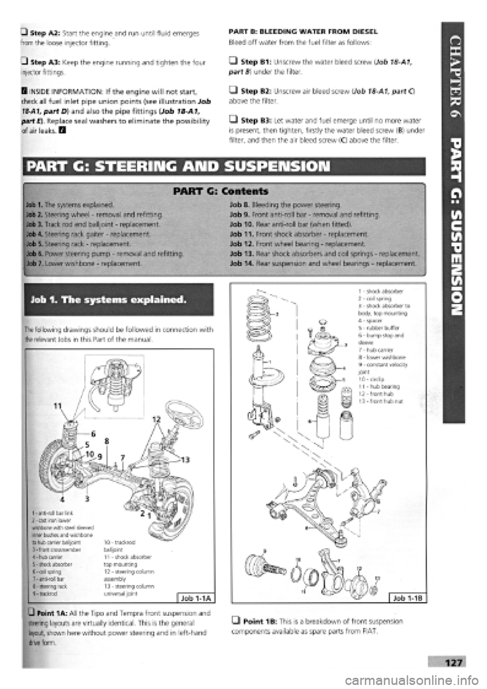
Job 1. The systems explained.
The
following drawings should be followed in connection with
the
relevant Jobs in this Part of the manual.
1
-
anti-roll bar link 2
-
cast iron lower wishbone with steel sleeved inner bushes and wishbone to hub carrier balijoint 3
-
front crossmember 4
-
hub carrier 5
-
shock absorber 6
-
coil spring 7
-
anti-roll bar 8
-
steering rack 9
-
trackrod
10 - trackrod balijoint 11 - shock absorber top mounting 12 - steering column assembly 13 - steering column universal joint Job 1-1A
G Point 1A: All the Tipo and Tempra front suspension and
steering layouts are virtually identical. This is the general LI Point 1B: This is a breakdown of front suspension
layout, shown here without power steering and in left-hand components available as spare parts from FIAT,
drive
form.
Page 124 of 171

Job 2. Steering wheel - removal
and refitting.
1 - coil spring 2 - trailing arm 3 - rubber bump stops 4 - handbrake cable 5 - axle beam
6 - anti-roll bar 7 - rear brake regulator 8 - shock absorber 9 - trailing arm hinge bolt
Job 1-1C
SAFETY FIRST!
• AIR BAGS. Because of the safety hazards, both
mechanical and chemical (the air bag contains an
explosive device)
-
we strongly recommend that a car
with an air bag fitted to its steering wheel should be
taken to a FIAT dealer to have its steering wheel
removed and refitted under controlled conditions.
STEERING WHEELS WITHOUT AIR BAGS ONLY
Q Point 1C: The rear suspension design shown here is
common to both Tipo and Tempra.
1 - beam axle 2 - rubber buffer pads 3 - shock absorber top bolt 4 - coil spring 5 - shock absorber 6 - bottom nut and bolt securing shock absorber to trailing arm 7 - trailing arm 8 - anti-roll bar 9 - nut and bolt securing trailing arm to beam axle 10 - stub axle/hub nut 11 - wheel hub 12 - stub axle 13
-
hub cap
Job 1-1D
Q Point 1D: This exploded drawing of the rear suspension
gives a clear view of how several of the assemblies are fitted.
• Step 3: Slacken the lock nut
(arrowed) on the track rod by just enough
to free the balljoint, but no
more.
• Step 4: Now undo the
balljoint to steering arm nut
until the bottom of the nut is
level with the end of the thread.
Job
3-3
Job 3. Track rod end balljoint -
replacement.
Q Step 1: Slacken the roadwheel nuts
on the side to be worked.
Q Step 2: Jack up and support the car
on axle stands and remove the road
wheel.
• Step 1: Undo the wheel
cover fixing bolts (positions
arrowed) from underneath.
• Step 2: Using a ring
spanner or socket and
supporting the wheel with the
other hand (see illustration
Job
2-1),
undo the centre
fixing nut and remove the
steering wheel.
H INSIDE INFORMATION!
Never use the steering column lock to stop the wheel
turning when removing and refitting the centre nut-this
could cause damage and would be a costly mistake. H
• Step 3: Refit in reverse order, tightening the fixing nut to
its specified torque. See Chapter
3,
Facts and Figures.
Page 125 of 171

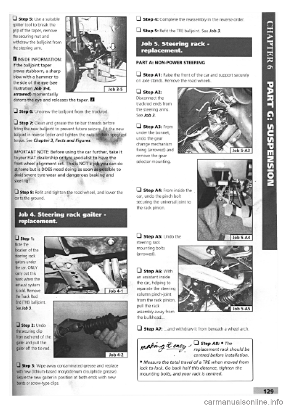
Job 4. Steering rack gaiter -
replacement.
• Step 1:
Note
the
location of the
steering rack
gaiters under
the car.
ONLY
carry out this
work when the
exhaust system
is cold.
Remove
Q Step 5: Use a suitable
splitter tool to break the
grip of the taper, remove
the securing nut and
withdraw the balljoint from
the steering arm.
B INSIDE INFORMATION:
If the balljoint taper
proves stubborn, a sharp
blow with a hammer to
the side of the eye (see
illustration Job
3-4,
arrowed) momentarily
distorts the eye and releases the taper. B
G Step 6: Unscrew the balljoint from the trackrod.
Q Step 7: Clean and grease the tie bar threads before
fitting the new balljoint to prevent future seizure,.fit the new
balljoint in reverse order and tighten the
torque. See Chapter 3, Facts and Figures.
1 ' ™
IMPORTANT NOTE: Before using the car further, take it
to
your FIAT dealership or tyre specialist to have the
front wheel alignment set. This4s NOT a job you can do
at home but is DOES need doing as soon as possible to
avoid severe tyre wear and dangerous braking and
steering!
Q Step 8: Refit and tighten the road wheel, and lower the
car to
the ground.
Q Step 3: Wipe away contaminated grease and replace
with new (lithium-based molybdenum disulphide grease).
Secure
the new gaiter in position at both ends with new
bands
or screw-type clips.
the Track
Rod
End
(TRE) balljoint.
See Job 3.
0 Step 2: Undo
the securing
clip
from
each end of the
gaiter
and
pull the
gaiter off the tie rod.
Q Step 4: Complete the reassembly in the reverse order.
• Step 5: Refit the TRE balljoint. See Job 3
Job 5. Steering rack -
replacement.
PART A: NON-POWER STEERING
Q Step A1: Raise the front of the car and support securely
on axle stands. Remove the road wheels.
• Step A5: Undo the
steering rack
mounting bolts
(arrowed).
• Step A2:
Disconnect the
trackrod ends from
the steering arms.
See Job 3.
Q Step A3: From
under the bonnet,
undo the gear
change mechanism
fixing (arrowed) and
remove the gear
selector mounting.
• Step A4: From inside the
car, undo the pinch bolt
securing the universal joint to
the rack pinion.
• Step A6: With
an assistant inside
the car, helping to
separate the steering
column pinch-joint
from the rack pinion,
pull the rack
assembly away from
the bulkhead...
• Step A7: ...and withdraw it from beneath a wheel arch.
replacement rack should be
centred before installation.
• Measure the total travel of a TRE when moved from
lock to lock. Go back half this distance, tighten the
mounting bolts, and your rack is centred.
Page 126 of 171

Q Step A9: Place the steering wheel in the dead ahead
position and engage the rack pinion splines with the column
coupling.
Q Step A10: Continue refitting in the reverse order of
removal.
• Step A11: Take your car to your nearest FIAT dealership
or tyre specialist to have the front wheel alignment set before
using the car further. This is NOT a job you can do at home
but is DOES need doing as soon as possible to avoid severe
tyre wear and dangerous braking and steering!
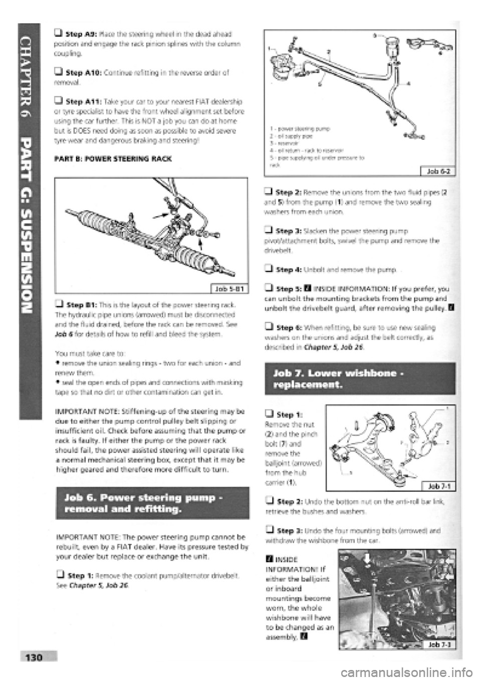
PART B: POWER STEERING RACK
LI Step B1: This is the layout of the power steering rack.
The hydraulic pipe unions (arrowed) must be disconnected
and the fluid drained, before the rack can be removed. See
Job 6 for details of how to refill and bleed the system.
You must take care to:
• remove the union sealing rings
-
two for each union
-
and
renew them.
• seal the open ends of pipes and connections with masking
tape so that no dirt or other contamination can get in.
IMPORTANT NOTE: Stiffening-up of the steering may be
due to either the pump control pulley belt slipping or
insufficient oil. Check before assuming that the pump or
rack is faulty. If either the pump or the power rack
should fail, the power assisted steering will operate like
a normal mechanical steering box, except that it may be
higher geared and therefore more difficult to turn.
Job 6. Power steering pump
removal and refitting.
IMPORTANT NOTE: The power steering pump cannot be
rebuilt, even by a FIAT dealer. Have its pressure tested by
your dealer but replace or exchange the unit.
[_) Step 1: Remove the coolant pump/alternator drivebelt.
See Chapter
5,
Job 26.
• Step 2: Remove the unions from the two fluid pipes (2
and 5) from the pump (1) and remove the two sealing
washers from each union.
Q Step 3: Slacken the power steering pump
pivot/attachment bolts, swivel the pump and remove the
drivebelt.
• Step 4: Unbolt and remove the pump.
• Step 5: B INSIDE INFORMATION: If you prefer, you
can unbolt the mounting brackets from the pump and
unbolt the drivebelt guard, after removing the pulley. I
• Step 6: When refitting, be sure to use new sealing
washers on the unions and adjust the belt correctly, as
described in Chapter
5,
Job 26
Job 7. Lower wishbone
replacement.
• Step 1:
Remove the nut
(2) and the pinch
bolt (7) and
remove the
balljoint (arrowed)
from the hub
carrier (1).
• Step 2: Undo the bottom nut on the anti-roll bar link,
retrieve the bushes and washers.
• Step 3: Undo the four mounting bolts (arrowed) and
withdraw the wishbone from the car.
H INSIDE
INFORMATION! If
either the balljoint
or inboard
mountings become
worn, the whole
wishbone will have
to be changed as an
assembly. E3
130
1 - power steering pump 2 - oil supply pipe 3 - reservoir 4 - oil return - rack to reservoir 5 - pipe supplying oil under pressure to rack Job
6-2