1988 FIAT TEMPRA engine oil
[x] Cancel search: engine oilPage 40 of 171

14C. Also open
the drain plug or
tap (B) at the
centre of the rear
flank of the
engine block on
both petrol and
diesel engines. Drain the coolant into a container. On models
with a separate expansion tank, detach the hose from the
expansion tank and drain the tank.
Q INSIDE INFORMATION: From time to time it's a good
idea to flush the cooling system. With the bottom hose
re-connected, disconnect and remove the top hose from
the radiator. Insert the end of a garden hose first into
the hose (packing the gap with a rag) and then the
radiator inlet, flushing the system in both directions until
the water comes out clear. Q
IMPORTANT NOTE: Flush first with the heater control
turned OFF until the engine and radiator are clear, so
that you don't flush sediment into the heater. Then with
the heater turned ON, flush the heater system out.
14D. To prevent air-locks
forming in the cooling
system as it is refilled (all
hoses and the drain plug
reconnected, of course!),
most models have two
air-bleed screws strategi-
cally positioned in the
system. These should be
opened before refilling.
The first (B or C) is
located on the right-
hand side of the radiator
(type dependant on
version)...
PART C: TRANSMISSION
• Job 15. Check manual gearbox oil level.
The combined oil level and filler plug is on the forward-facing
side of the gearbox. Check the level with the car on level
ground.
15. From beneath the car, wipe
around the filler plug with a rag
to prevent dirt contamination.
Remove the plug
-
using a 10
mm Allen key
-
and top-up if
necessary, using the specified
Tutela transmission oil (see
Chapter
3,
Facts and
Figures), until oil just dribbles
from the filler hole. Refit the
plug.
14E.... and the
second (D)
-
when fitted
-
is
found on the
heater hose near
the top of the
engine. Only
undo the screws
by two or three
turns. Retighten both screws when air-free coolant emerges.
This is the petrol engine...
14F. ...and this
the diesel engine
location.
H INSIDE
INFORMATION:
It seems that
latest Tipos and
Tempras were
built without some or all bleed screws. Ryauto
recommend removing the highest point of the top hose,
refilling with coolant, while an assistant refits the hose
smartly, losing as little coolant as possible. D
Refill the cooling system with a 50/50 mixture of clean water
and fresh Paraflu anti-freeze. Tighten the bleed screws (or
hose) when coolant, and not air, comes out steadily. Run the
engine for a few minutes and bleed again.
IMPORTANT NOTE: It is highly likely that more air will be
dislodged when you first use the car. Keep your eye on
the coolant level (See Job 2)
-
perhaps carrying some
50/50 diluted coolant with you for the first few journeys.
• Job 16. Change manual gearbox oil.
16. The combined
gearbox and final
drive oil should be
drained at the time
shown in the
Service Interval
Chart. Do so only
after the car has
been used and the
gearbox oil is warm, so that it flows well. Remove the drain
plug (on the end-face of the gearbox, accessed from beneath
the car
-
not much room to get a spanner in!) and drain the
oil into a container. (See page 8 on oil disposal.) Leave for 10
minutes to drain completely, and refill with the correct grade
of Tutela transmission oil through the level/filler plug, as
described in Job 15.
Page 41 of 171
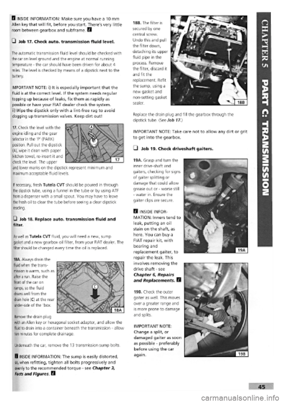
IMPORTANT NOTE: Take care not to allow any dirt or grit
to get into the gearbox.
• Job 19. Check driveshaft gaiters.
45
B INSIDE INFORMATION: Make sure you have a 10 mm
Allen key that will fit, before you start. There's very little
room between gearbox and subframe. B
Q Job 17. Check auto, transmission fluid level.
The
automatic transmission fluid level should be checked with
the
car on level ground and the engine at normal running
temperature
-
the car should have been driven for about 4
miles. The level is checked by means of a dipstick next to the
battery.
IMPORTANT NOTE: i) It is especially important that the
fluid is at the correct level. If the system needs regular
topping up because of leaks, fix them as rapidly as
possible or have your FIAT dealer check the system,
ii) Wipe the dipstick only with a lint-free rag to avoid
clogging up transmission valves. Keep dirt out!
18B. The filter is
secured by one
central screw.
Undo this and pull
the filter down,
detaching its upper
fluid pipe in the
process. Remove
the filter, discard it
and fit the
replacement. Refit
the sump, using a
new gasket and
non-setting gasket
sealer.
Replace the drain plug and fill the gearbox through the
dipstick tube. {See Job
17.)
19A. Grasp and turn the
inner drive-shaft and
gaiters, checking for signs
of gaiter splitting or
damage that could allow
grease out or
-
worse still
-
water in. Ensure the
gaiter clips are secure.
Q INSIDE INFOR-
MATION: Inners tend to
leak, putting an oil
stain on the shaft, as
here. You can buy a
FIAT repair kit, with
bearing and
replacement gaiter, to
repair the leak. This
involves removing the
drive shaft
-
see
Chapter 6, Repairs
and Replacements. B
19B. Check the outer
gaiter as well. This moves
over a greater range and
is more prone to damage
and splits.
IMPORTANT NOTE:
Change a split, or
damaged gaiter as soon
as possible
-
preferably
before using the car
again.
If
necessary,
fresh Tutela CVT should be poured in through
the
dipstick tube, using a funnel in the tube or by using ATF
from
a dispenser with a small spout. You may have to leave
the fresh
oil to clear the tube before seeing a clear dipstick
reading.
G Job 18. Replace auto, transmission fluid and
filter.
As well as
Tutela CVT fluid, you will need a new, sump
gasket
and
a new gearbox oil filter, from your FIAT dealer. The
filter
should
be changed every time the oil is replaced.
18A.
Always drain the
fluid when
the trans-
mission
is
warm, such as
after a
run. Raise the
front
of the car on
ramps,
so the fluid
drains well
from the
drain
hole (C) at the rear
under-side of the 'box.
Remove
the drain plug
with an
Allen key or hexagonal socket adaptor, and allow the
fluid to
drain into a container beneath the transmission
-
allow
ten
minutes for complete drainage.
Underneath the car, remove the 13 transmission sump bolts.
H INSIDE INFORMATION: The sump is easily distorted,
so,
when refitting, tighten all bolts progressively and
evenly to the recommended torque
-
see Chapter 3,
Facts and Figures. B
17.
Check the level with the
engine idling and the gear
selector in the 'P' (PARK)
position. Pull out the dipstick
(A),
wipe it clean with paper
kitchen towel, re-insert it and
check the level. The upper
and
lower marks on the dipstick represent minimum and
maximum acceptable fluid levels.
Page 42 of 171
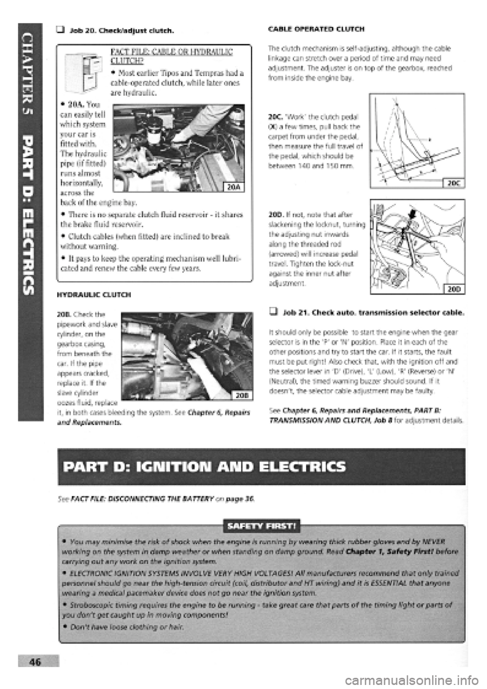
• Job 20. Check/adjust clutch. CABLE OPERATED CLUTCH
The clutch mechanism is self-adjusting, although the cable
linkage can stretch over a period of time and may need
adjustment. The adjuster is on top of the gearbox, reached
from inside the engine bay.
20C. 'Work' the clutch pedal
(X) a few times, pull back the
carpet from under the pedal,
then measure the full travel of
the pedal, which should be
between 140 and 150 mm.
/
\
/ \
/ u / Xl
1 ' ' / . V y 2
Jdi V 1 \
X. 1 —
20C
HYDRAULIC CLUTCH
20B. Check the
pipework and slave
cylinder, on the
gearbox casing,
from beneath the
20D. If not, note that after
slackening the locknut, turning
the adjusting nut inwards
along the threaded rod
(arrowed) will increase pedal
travel. Tighten the lock-nut
against the inner nut after
adjustment.
• Job 21. Check auto, transmission selector cable.
It should only be possible to start the engine when the gear
selector is in the 'P' or 'N' position. Place it in each of the
other positions and try to start the car. If it starts, the fault
must be put right! Also check that, with the ignition off and
the selector lever in 'D' (Drive), 'L' (Low), 'R' (Reverse) or 'N'
(Neutral), the timed warning buzzer should sound. If it
doesn't, the selector cable adjustment may be faulty.
See Chapter
6,
Repairs and Replacements, PART B:
TRANSMISSION AND CLUTCH, Job 8 for adjustment details.
PART D: IGNITION AND ELECTRICS
See FACT FILE: DISCONNECTING THE BATTERY on page 36
SAFETY FIRST!
• You may minimise the risk of shock when the engine is running by wearing thick rubber gloves and by NEVER
working on the system in damp weather or when standing on damp ground. Read Chapter 1, Safety First! before
carrying out any work on the ignition system.
• ELECTRONIC IGNITION SYSTEMS INVOLVE VERY HIGH VOLTAGES! All manufacturers recommend that only trained
personnel should go near the high-tension circuit (coil, distributor and HT wiring) and it is ESSENTIAL that anyone
wearing a medical pacemaker device does not go near the ignition system.
• Stroboscopic timing requires the engine to be running
-
take great care that parts of the timing light or parts of
you don't get caught up in moving components!
• Don't have loose clothing or hair.
46
FACT FILE: CABLE OR HYDRAULIC
CLUTCH?
• Most earlier Tipos and Tempras had a
cable-operated clutch, while later ones
are hydraulic.
• 2 OA. You
can easily tell
which system
your car is
fitted with.
The hydraulic
pipe (if fitted)
runs almost
horizontally,
across the
back of the engine bay.
• There is no separate clutch fluid reservoir
-
it shares
the brake fluid reservoir.
• Clutch cables (when fitted) are inclined to break
without warning.
• It pays to keep the operating mechanism well lubri-
cated and renew the cable every few years.
car. If the pipe
appears cracked,
replace it. If the
slave cylinder
oozes fluid, replace
it, in both cases bleeding the system. See Chapter
6,
Repairs
and Replacements.
Page 43 of 171
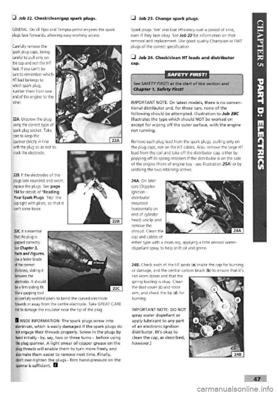
J Job 22. Check/clean/gap spark plugs. Q Job 23. Change spark plugs.
GENERAL. On all Tipo and Tempra petrol engines the spark
plugs
face forwards, allowing easy working access.
Carefully remove the
spark plug caps, being
careful to pull only on
the cap and
not the HT
lead. If you can't be
sure
to remember which
HT lead
belongs to
which spark plug,
number them from one
end
of the engine to the
other.
22B. If the electrodes of the
plugs look rounded and worn,
replace
the plugs. See page
154
for details of 'Reading
Your Spark Plugs. Nip' the
cap
tight with pliers, so that it
can't come loose.
Spark plugs 'tire' and lose efficiency over a period of time,
even if they look okay. See Job 22 for information on their
removal and replacement. Use good quality Champion or FIAT
plugs of the correct specification.
• Job 24. Check/dean HT leads and distributor
cap.
See SAFETY FIRST! at the start of this section and
Chapter 1, Safety First!
IMPORTANT NOTE: On latest models, there is no conven-
tional distributor and, for those cars, none of the
following should be attempted. Illustration to Job 28C
illustrates the type which should NOT be worked on
except for wiping off the outer surface, with the engine
not running.
Remove each plug lead from the spark plugs, pulling only on
the plug caps, not on the HT cables. Also, remove the large HT
lead from the coil and take off the distributor cap, either by
popping off its spring retainers if the distributor is on the side
of the engine (front of engine bay
-
see illustration 25A) or by
undoing the two retaining screws.
24A. On later
cars (Digiplex
ignition -
distributor
mounted
horizontally on
end of cylinder
head) unclip and
remove the
22A. Unscrew the plug
using
the correct type of
spark plug socket. Take
care
to keep the
spanner strictly in line
with the plug so as not to
crack the electrode.
22C.
it
is
essential
that the
plug is
gapped
correctly.
See Chapter 3,
Facts
and Figures.
Use a
feeler blade
of the
correct
thickness, sliding it
between
the
electrodes. It should
be a firm
sliding fit.
Use a
gapping tool
or
carefully wielded pliers to bend the curved electrode
towards
or away from the centre electrode. Take GREAT CARE
not to
damage the insulator near the tip of the plug.
H INSIDE INFORMATION: The spark plugs screw into
aluminium, which is easily damaged if the spark plugs do
not
engage their threads properly. Screw in the plugs by
hand initially
-
by, say, two or three turns
-
before using
the plug spanner. A light smear of copper grease on the
plug
threads will enable them to turn more freely and
also
make them easier to remove next time. Finally,
don't over-tighten the plugs
-
firm hand-pressure on the
spanner is sufficient. D
IMPORTANT NOTE: DO NOT
spray water dispellant or
apply lubricant to any part
of an electronic ignition
distributor. (It's okay to
clean the cap, as described,
however.)
shroud. Clean the
cap and cables of
either type with a clean rag, applying a little aerosol water-
dispellant spray to help shift oil and grime.
24B. Check each of the HT posts (a) inside the cap for burning
or damage, and the central carbon brush (b) to ensure that it's
not worn down and that the
spring loading is okay. Clean
the dust cover (c) and rotor
arm, and check the tip (d) for
burning.
Page 44 of 171

• Job 25. Check ignition timing.
_ FACT FILE: IGNITION SYSTEM TYPES
Two different types of electronic ignition
systems have been fitted to the petrol
engines covered by this manual.
The earlier Breakerless Inductive Discharge System can
be adjusted. Its distributor is fitted as shown in illus-
tration 25A.
The later, Digiplex 2 system, has an integrated ignition
and fuel injection control system and any checks and
adjustments will need to be carried out by your FIAT
dealership with the appropriate diagnostic equipment.
See Job 28.
MAGNETI MARELLI BREAKERLESS INDUCTIVE
DISCHARGE IGNITION SYSTEM
CHECK VACUUM AND MECHANICAL ADVANCE SYSTEMS
25A. This is the
location of the break-
erless electronic
ignition components in
the car. The distributor
(1) is fitted to the front
of the block while the
ignition coil
(2)
is
alongside the battery.
25B. This type of distributor can be
identified by the electronic ignition
control module (a) and the vacuum
advance unit (b), not fitted to other
ignition types.
• the engine must be at
ature.
• the idle speed/mixture/CO adjustments must be correct
-
see Job 35.
• Start the engine and run it at between 750 and 850 rpm.
• Point the timing light at the crankshaft pulley timing mark
and ensure that the mark lines up with the 10 degrees Before
Top Dead Centre (BTDC) mark on the timing belt cover.
• If the reading is 'out' stop the engine and slacken the clamp
nut on the distributor so that the distributor can just be turned
with firm hand pressure.
• Turn the distributor a very small amount, restart the engine
and check again.
• Repeat the procedure until, with the engine running, the
crankshaft pulley timing mark lines up with the 10 degree
BTDC mark. Then tighten the nut securing the distributor to
the engine block.
You can now check the vacuum advance system as follows:
• increase the engine speed to approximately 2,000 rpm and,
with the timing light pointed at the timing marks, make a
mental note of the position of the mark on the crankshaft
pulley in relation to the timing belt cover. If the position is no
further advanced than 10 degrees BTDC, the mechanical
advance system inside the distributor is probably seized.
• stop the engine, reconnect the vacuum advance pipe and
repeat the procedure.
• you should see a further amount of advance taking place
and if not, the diaphragm inside the vacuum advance
mechanism is probably punctured.
• if either or both of these faults have occurred, your engine
will run uneconomical^ and inefficiently and it may pay you to
fit a new distributor.
MAGNETI MARELLI DIGIPLEX 2 ELECTRONIC
IGNITION
25D. This is the layout of the Digiplex ignition system, viewed
from over the engine looking towards the left-side of the car.
The ignition coil (1) is adjacent to the battery. The electronic
control unit (2) is nearer to the engine bay sidewall. The
distributor (3) is mounted on the end of the cylinder head and
the rpm and Top Dead Centre (TDC) sensor (4) is located on
the crankshaft cover on the flywheel side.
IMPORTANT NOTE: Before
checking the ignition timing,
you must be certain that:
• the pipe from the distributor
vacuum unit is disconnected
from the distributor and plugged.
its normal operating temper-
instructions. The
timing light should
always be connected
to No.
1
spark plug
lead
-
the one nearest
the timing belt end of
the engine.
48
25C. To check the ignition timing, connect up a stroboscopic
lamp, either as shown on the inset or in accordance with the
manufacturer's
Page 47 of 171

28C. With very latest
'distributorless' system,
disconnect the multi-plug
from the base of the 'black
box'.
28D. With the two earlier
systems, disconnect the
multi-plug leading to the
distributor/control unit
from the ignition coil
behind the battery.
FACT FILE: CRANKING AN ENGINE
WITH ELECTRONIC IGNITION
Severe damage can be
caused to the ignition
system if the engine is
cranked with plugs/leads
removed
-
and a severe
electric shock can be
experienced.
PART E: FUEL AND EXHAUST
SAFETY FIRST!
Always
wear impervious gloves so that fuel cannot
come
in contact with your
skin.
It can induce cancer.
Q Job 29. Check fuel pipes for leaks.
Check the fuel lines from the fuel tank and into the engine
compartment, looking for signs of chafing, splits and perishing
of the
rubber and plastic parts. Ensure any worm-drive hose
clips used
on the connections are firm and secure.
Q Job 30. Change petrol air filter.
IMPORTANT NOTE: If the HC reading when measured at
the end of the exhaust pipe is outside of the recom-
mended limit while that measured upstream of the
catalytic converter is OK, the cat. is almost certainly
faulty. Have it double-checked by your dealer before
replacing it
-
an expensive component!
30C. Pull on the
tabs
-
and watch
that the springs
don't fall on the
floor as you release
the catches!
30D. Lower the
filter cover and lift
out the filter
element.
31B. If you want to
take the cover right
off, you will have to
unscrew the air
hose clamp
(arrowed). Remove
and replace the
filter element (A).
• Job 31.
Change diesel
air filter.
31A. Take out the
four screws
(arrowed) and lift
off the cover (B). 30B. ...and release
the two
fasteners
(a) and the
two
spring clips
(b).
30A. Unscrew the
two
screws
(arrowed)...
51
Page 48 of 171
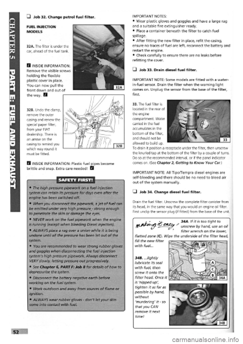
• Job 32. Change petrol fuel filter. IMPORTANT NOTES:
• Wear plastic gloves and goggles and have a large rag
and a suitable fire extinguisher ready.
• Place a container beneath the filter to catch fuel
spillage.
• After fitting the new filter in place, refit the casing,
ensure no traces of fuel are left, reconnect the battery and
restart the engine.
• Check carefully to ensure there are no leaks before
refitting the cover.
• Job 33. Drain diesel fuel filter.
IMPORTANT NOTE: Some models are fitted with a water-
in-fuel sensor. Drain the filter when the warning light
comes on. Unplug the sensor from the base of the filter,
first.
FUEL INJECTION
MODELS
32A. The filter is under the
car, ahead of the fuel tank.
E3 INSIDE INFORMATION:
Remove the visible screws
holding the flexible
plastic cover in place.
You can now pull the
front down and out of
the way. E3
32B. Undo the clamp,
remove the outer
casing and renew the
special paper filter,
from your FIAT
dealership. There is
an arrow on the
casing to remind you
which way round it
must be fitted.
33. The fuel filter is
located in the rear of
the engine
compartment. Water
carried in the fuel
accumulates in the
bottom of the filter,
and should not be
allowed to build up.
To drain it position a receptacle under the filter, then unscrew
the knurled tap at the bottom of the filter by a couple of turns.
Do so at the recommended interval, or if the panel indicator
comes on. (See Chapter
2,
Getting to Know Your
Car.)
H INSIDE INFORMATION: Plastic fuel pipes become
brittle and snap. Extra care needed! E3
SAFETY FIRST!
• The high pressure pipework on a fuel injection
system can retain its pressure for days even after the
engine has been switched off.
• When you disconnect the pipework, a jet of fuel can
be emitted under very high pressure
-
strong enough
to penetrate the skin or damage the eyes.
• NEVER work on the fuel pipework when the engine
is running (except when bleeding Diesel injectors).
• ALWAYS place a rag over a union while it is being
undone until all the pressure has been let out of the
system.
• You are recommended to wear strong rubber gloves
and goggles when disconnecting the fuel injection
system's high pressure pipework. Always disconnect
VERY slowly, letting pressure out progressively.
• See Chapter 6, PART F: Job 8 for details of how to
depressurise the system.
• Disconnect the battery negative earth before
working on the fuel system.
• Work outdoors and away from sources of flame or
ignition.
• ALWAYS wear rubber gloves
-
don't let your
skin
come into contact with fuel.
IMPORTANT NOTE: All Tipo/Tempra diesel engines are
self-bleeding and there should be no need to bleed air
out of the system manually.
• Job 34. Change diesel fuel filter.
Drain the fuel filter. Unscrew the complete filter canister from
its head, in the same way that you would an engine oil filter.
First undip the sensor plug (if fitted) from the base of the unit.
^ 34A. If it is too tight to
^^ - unscrew by hand, use an oil
filter wrench on the lower,
flatted zone (C). Wipe the underside of the filter head,
fill the new filter
with fuel...
34B. ...lightly
lubricate its seal
with fuel, then
screw it onto the
filter head. Once it
is 'nipped up',
tighten it as far as
possible by hand,
without
'murdering' it
-
so
that you CAN
remove it next
time!
Page 53 of 171
PART F: STEERING AMD SUSPENSION
G Job 42. Check front wheel bearings.
In
order to check for wear:
• raise the front of the car on axle stands (see Chapter 1,
Safety First!)
• place the gearbox in neutral
• pull the handbrake securely on and chock the rear wheels
Try
spinning each wheel (as far as possible with a front-drive
car), feeling for rough rotation. Rock the wheel about its
centre, feeling for excess bearing play.
D INSIDE INFORMATION: If a wheel bearing is worn, you
will normally hear a noise on the outer, loaded bearing
when cornering. D
G Job 43. Check front suspension.
BOTTOM BALL JOINT
Jack
up
the car underneath the suspension lower arm
(wishbone), so that the wheel is two inches off the ground.
See Chapter
1,
Safety First.
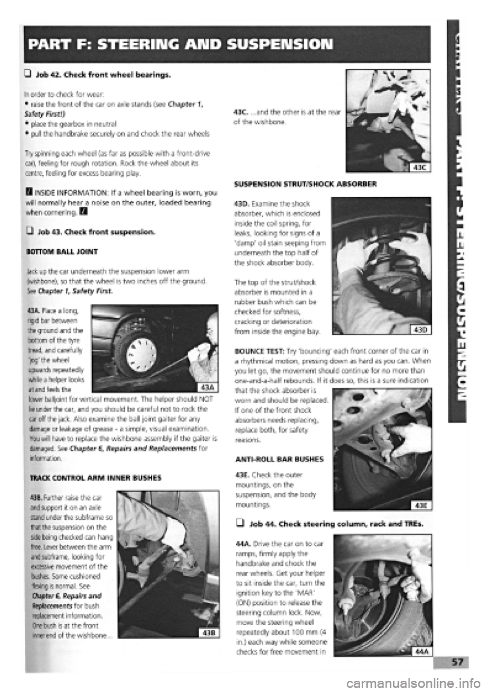
SUSPENSION STRUT/SHOCK ABSORBER
43D. Examine the shock
absorber, which is enclosed
inside the coil spring, for
leaks, looking for signs of a
'damp' oil stain seeping from
underneath the top half of
the shock absorber body.
The top of the strut/shock
absorber is mounted in a
rubber bush which can be
checked for softness,
cracking or deterioration
from inside the engine bay.
43A. Place a long,
rigid bar between
the
ground and the
bottom of the tyre
tread, and carefully
'jog' the wheel
upwards repeatedly
while a helper looks
at and
feels the
lower balljoint for vertical movement. The helper should NOT
lie
under the car, and you should be careful not to rock the
car
off
the jack.
Also examine the ball joint gaiter for any
damage
or leakage of grease
-
a simple, visual examination.
You will
have to replace the wishbone assembly if the gaiter is
damaged. See Chapter
6,
Repairs and Replacements for
information.
TRACK CONTROL ARM INNER BUSHES
43B. Further raise the car
and
support it on an axle
stand
under the subframe so
that the
suspension on the
side being
checked can hang
free. Lever between the arm
and
subframe, looking for
excessive movement of the
bushes. Some cushioned
flexing
is
normal. See
Chapter
6, Repairs and
Replacements for bush
replacement information.
One bush is
at the front
inner end
of the wishbone...
ANTI-ROLL BAR BUSHES
43E. Check the outer
mountings, on the
suspension, and the body
mountings.
• Job 44. Check steering column, rack and TREs.
44A. Drive the car on to car
ramps, firmly apply the
handbrake and chock the
rear wheels. Get your helper
to sit inside the car, turn the
ignition key to the 'MAR'
(ON) position to release the
steering column lock. Now,
move the steering wheel
repeatedly about 100 mm (4
in.) each way while someone
checks for free movement in
BOUNCE TEST: Try 'bouncing' each front corner of the car in
a rhythmical motion, pressing down as hard as you can. When
you let go, the movement should continue for no more than
one-and-a-half rebounds. If it does so, this is a sure indication
that the shock absorber is
worn and should be replaced.
If one of the front shock
absorbers needs replacing,
replace both, for safety
reasons.