1988 FIAT TEMPRA seat adjustment
[x] Cancel search: seat adjustmentPage 10 of 171
• 9. DOOR MIRROR ADJUSTMENT
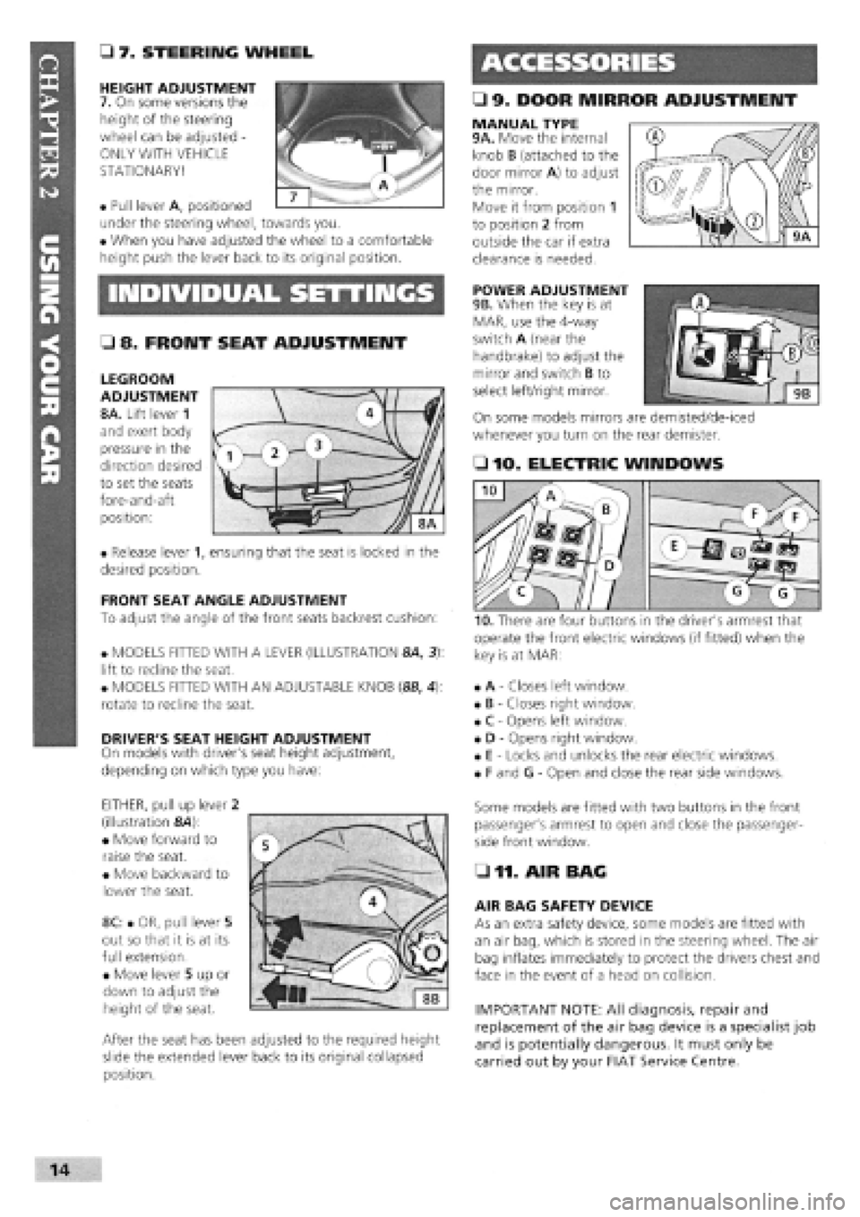
• 7. STEERING WHEEL
HEIGHT ADJUSTMENT
7. On some versions the
height of the steering
wheel can be adjusted -
ONLY WITH VEHICLE
STATIONARY!
• Pull lever A, positioned
under the steering wheel, towards you.
• When you have adjusted the wheel to a comfortable
height push the lever back to its original position.
MANUAL TYPE 9A. Move the internal
knob B (attached to the
door mirror A) to adjust
the mirror.
Move it from position 1
to position 2 from
outside the car if extra
clearance is needed.
INDIVIDUAL SETTINGS POWER ADJUSTMENT
9B. When the key is at
MAR, use the 4-way
switch A (near the
handbrake) to adjust the
mirror and switch B to
select left/right mirror.
On some models mirrors are demisted/de-iced
whenever you turn on the rear demister.
• 8. FRONT SEAT ADJUSTMENT
LEGROOM
ADJUSTMENT
8A. Lift lever 1
and exert body
pressure in the
direction desired
to set the seats
fore-and-aft
position:
• Release lever 1, ensuring that the seat is locked in the
desired position.
FRONT SEAT ANGLE ADJUSTMENT
To adjust the angle of the front seats backrest cushion:
• MODELS FITTED WITH A LEVER (ILLUSTRATION 8A, 3):
lift to recline the seat.
• MODELS FITTED WITH AN ADJUSTABLE KNOB (8B, 4):
rotate to recline the seat.
DRIVER'S SEAT HEIGHT ADJUSTMENT
On models with driver's seat height adjustment,
depending on which type you have:
EITHER, pull up lever 2
(illustration &4):
• Move forward to
raise the seat.
• Move backward to
lower the seat.
8C: • OR, pull lever 5
out so that it is at its
full extension.
• Move lever 5 up or
down to adjust the
height of the seat.
After the seat has been adjusted to the required height
slide the extended lever back to its original collapsed
position.
• 10. ELECTRIC WINDOWS
operate the front electric windows (if fitted) when the
key is at MAR:
• A
-
Closes left window.
• B
-
Closes right window.
• C
-
Opens left window.
• D
-
Opens right window.
• E
-
Locks and unlocks the rear electric windows.
• F and G
-
Open and close the rear side windows.
Some models are fitted with two buttons in the front
passenger's armrest to open and close the passenger-
side front window.
• 11. AIR BAG
AIR BAG SAFETY DEVICE
As an extra safety device, some models are fitted with
an air bag, which is stored in the steering wheel. The air
bag inflates immediately to protect the drivers chest and
face in the event of a head on collision.
IMPORTANT NOTE: All diagnosis, repair and
replacement of the air bag device is a specialist job
and is potentially dangerous. It must only be
carried out by your FIAT Service Centre.
I
Page 58 of 171
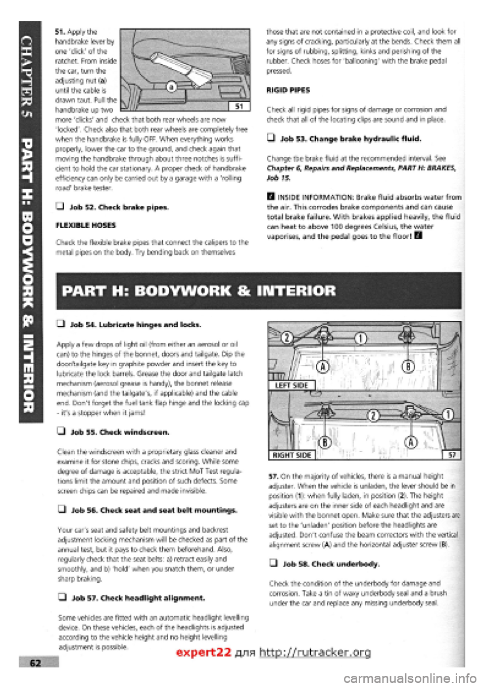
51. Apply the
handbrake lever by
one 'click' of the
ratchet. From inside
the car, turn the
adjusting nut (a)
until the cable is
drawn taut. Pull the
handbrake up two
more 'clicks' and check that both rear wheels are now
'locked'. Check also that both rear wheels are completely free
when the handbrake is fully OFF. When everything works
properly, lower the car to the ground, and check again that
moving the handbrake through about three notches is suffi-
cient to hold the car stationary. A proper check of handbrake
efficiency can only be carried out by a garage with a 'rolling
road' brake tester.
Q Job 52. Check brake pipes.
FLEXIBLE HOSES
Check the flexible brake pipes that connect the calipers to the
metal pipes on the body. Try bending back on themselves
those that are not contained in a protective coil, and look for
any signs of cracking, particularly at the bends. Check them all
for signs of rubbing, splitting, kinks and perishing of the
rubber. Check hoses for 'ballooning' with the brake pedal
pressed.
RIGID PIPES
Check all rigid pipes for signs of damage or corrosion and
check that all of the locating clips are sound and in place.
• Job 53. Change brake hydraulic fluid.
Change the brake fluid at the recommended interval. See
Chapter
6,
Repairs and Replacements, PART H: BRAKES,
Job 15.
H INSIDE INFORMATION: Brake fluid absorbs water from
the air. This corrodes brake components and can cause
total brake failure. With brakes applied heavily, the fluid
can heat to above 100 degrees Celsius, the water
vaporises, and the pedal goes to the floor! B
PART H: BODYWORK & INTERIOR
• Job 54. Lubricate hinges and locks.
Apply a few drops of light oil (from either an aerosol or oil
can) to the hinges of the bonnet, doors and tailgate. Dip the
door/tailgate key in graphite powder and insert the key to
lubricate the lock barrels. Grease the door and tailgate latch
mechanism (aerosol grease is handy), the bonnet release
mechanism (and the tailgate's, if applicable) and the cable
end. Don't forget the fuel tank flap hinge and the locking cap
- it's a stopper when it jams!
• Job 55. Check windscreen.
Clean the windscreen with a proprietary glass cleaner and
examine it for stone chips, cracks and scoring. While some
degree of damage is acceptable, the strict MoT Test regula-
tions limit the amount and position of such defects. Some
screen chips can be repaired and made invisible.
• Job 56. Check seat and seat belt mountings.
Your car's seat and safety belt mountings and backrest
adjustment locking mechanism will be checked as part of the
annual test, but it pays to check them beforehand. Also,
regularly check that the seat belts: a) retract easily and
smoothly, and b) 'hold' when you snatch them, or under
sharp braking.
Q Job 57. Check headlight alignment.
Some vehicles are fitted with an automatic headlight levelling
device. On these vehicles, each of the headlights is adjusted
according to the vehicle height and no height levelling
adjustment is possible.
57. On the majority of vehicles, there is a manual height
adjuster. When the vehicle is unladen, the lever should be in
position (1): when fully laden, in position (2). The height
adjusters are on the inner side of each headlight and are
visible with the bonnet open. Make sure that the adjusters are
set to the 'unladen' position before the headlights are
adjusted. Don't confuse the beam correctors with the vertical
alignment screw (A) and the horizontal adjuster screw (B).
• Job 58. Check underbody.
Check the condition of the underbody for damage and
corrosion. Take a tin of waxy underbody seal and a brush
under the car and replace any missing underbody seal.
expert22 fl/ia http://rutracker.org
RIGHT SIDE
Page 59 of 171

—1 Job 59. Check spare tyre.
This
job should ideally be carried out every month or two
-
you
never know when you're going to need that spare! But if you
haven't remembered, do it at the time shown on the Service
Interval Chart at the latest.
Q INSIDE INFORMATION: Put in the maximum recom-
mended pressure for heavy-duty use
-
it's always easier
to let some air out if necessary, than to put some in. Lift
the spare out check the 'hidden' lower side wall
for cracking. See Job 6. E9
PART I: ROAD TEST
Q Job 62. Road test and specialist check
-
after
every service.
Before you can claim to have 'finished' working on your car,
you must check it, test it, and, if necessary, have a qualified
mechanic check it over for you.
If you
are not a qualified mechanic, we strongly recommend
having someone who is a properly qualified mechanic
-
your
FIAT dealership perhaps
-
inspect all of the car's safety-related
items
after they have been worked on at home and before
using
the car on the road.
You'll have to remove the toolkit and the wheel to get at the
valve
-
under the boot floor on most models but to one side of
the rear compartment on Estate versions.
• Job 60. Change pollen filter.
When fitted to the fresh air intake, replace it at the scheduled
mileage interval.
• Job 61. Replace airbag gas generator.
Have your FIAT dealer replace the airbag gas generator 10
years after the car was built
-
see the label inside the car's
glove compartment door.
• Before setting out, check that the lights, indicators and in-
car controls, as well as seat belts and seat adjustments, all
work correctly.
• Run the car for several minutes before setting out then turn
off, check fluid levels and check underneath for leaks.
• Check that the steering moves freely in both directions and
that the car does not 'pull' one way or the other when driving
in a straight line
-
but do bear in mind the effect of the
camber on the road.
• Make sure that the brakes work effectively, smoothly and
without the need for 'pumping'. There should be no juddering
or squealing.
• Check that the car does not 'pull' from one side to the
other when you brake firmly from around 40 mph. (Don't
cause a skid and don't try this if there is any following traffic.)
"V,
WURTH PRODUCTS FROM FIAT
A.
Wurth produce a huge range of very high quality, FIAT-
approved products, from zinc-rich aerosol paints,
rust-proofing products and the safety-related items shown
here...
B. ...to electrical connectors and tools and that wonderful
'shrink-fit' wire insulation tubing
-
slide it on, heat it up, and it
'shrinks' into place and can't come undone again. See your
FIAT dealer or other specialist supplier for the vast range of
top-quality Wurth products.
Page 67 of 171

G Step 6: Fit the four or five smaller bolts, according to
model (see illustration Job
3-4,
arrowed) close to the spark
plug holes, and tighten to their specified torque. See Chapter
3, Facts
and Figures.
G Step 7: All items previously removed in Job 2 can now be
fitted in reverse order. When connecting the exhaust always
use a
new flange gasket.
G Step 8: Ensure that all connections are sound and secure.
G Step 9: All items previously removed in Job 2 can now be
fitted in reverse order. Refer to Job
1
when fitting the timing
belt.
When connecting the exhaust always use a new flange
gasket.
G Step 10: Ensure that all connections are sound and
secure.
G Step 11: Top up the cooling system with the correct
50/50
solution of FL 'Tutela' anti-freeze solution. Check the
oil
level.
• Step 5: Clean and check all components for wear and
signs of 'scuffing'.
B INSIDE INFORMATION! If the camshaft is changed, the
followers should be changed as well. If the bores in the
housing have 'picked up', these cannot be machined and
the housing should be replaced together with new cam
followers. B
• Step 6: Refit the camshaft to the cam housing and insert
the cam followers and shims in their correct bores, using
grease to keep them in place. For adjustment of valve clear-
ances see Job 7.
2 ZeASt, s * when re'inserti"9the
nfW^c/ !X J?^ camshaft, it can be difficult
to get the camshaft fully in
to its end seal. DON'T try hammering it in
-
all you'll
do is damage the seal. Lubricate the seal with fresh
engine oil, insert the camshaft until it is aligned with
and just touching the seal. Push the camshaft with a
twisting motion until it eases its way into the seal.
Job 4. Petrol engine.
Cylinder head - dismantling and
overhauling.
G Step 3: Remove the
cam
followers and shims
from
the housing,
keeping them in the
correct order for refitting
in the
same positions.
Refer to the illustration Job
2-1
for the components covered
in this
Job.
G Step 1: Remove the camshaft housing from the cylinder
head. See Job 2.
G Step 2: Remove the
camshaft housing end
plate
(or the distributor
mounted in the same
place on
certain models).
G Step 4: Slide the
camshaft out, taking
care not to damage the
camshaft bearings with
the cam
lobes.
• Step 7: Use a suitable valve spring compressor to
compress each spring in turn to allow the removal of the split
collets from the valve stems. Inexpensive valve spring
compressors are readily available from auto, accessory stores.
Take care not to lose the collets when releasing the spring
compressor.
Q Step 9: The valve spring caps, springs and spring seats
can all be lifted clear and the valves withdrawn from their
guides.
• Step 8:
These are the
items to be
removed once
the valve is
withdrawn.
1 - flat washer 2 - lower cap 3 - inner spring
4 - outer spring 5 - upper cap 6 - collets Job 4-8
Page 98 of 171
Job 8. Automatic gear selector
control cable - replacement.
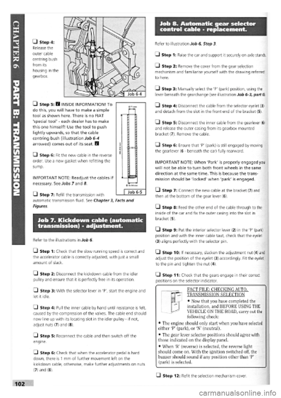
• Step 4:
Release the
outer cable
centring bush
from its
housing in the
gearbox.
• Step 5: H INSIDE INFORMATION! To
do this, you will have to make a simple
tool as shown here. There is no FIAT
'special tool'
-
each dealer has to make
this one himself! Use the tool to push
lightly upwards, so that the cable
centring bush (illustration Job
6-4
arrowed) comes out of its seat. B
• Step 6: Fit the new cable in the reverse
order. Use a new gasket when refitting the
sump.
IMPORTANT NOTE: Readjust the cables if
necessary. See Jobs 7 and 8.
Q Step 7: Refill the transmission with
automatic transmission fluid. See Chapter
3,
Facts and
Figures.
Job 7. Kickdown cable (automatic
transmission) - adjustment.
Refer to the illustrations in Job 6.
Q Step 1: Check that the slow running speed is correct and
the accelerator cable is correctly adjusted, with just a small
amount of slack.
Q Step 2: Disconnect the kickdown cable from the idler
pulley and ensure that it is perfectly free in its operation.
• Step 3: With the selector lever in 'P', start the engine and
let it idle.
Q Step 4: Pull the inner cable by hand until resistance is felt,
caused by the compression of the valves. The cable end should
now line up with its locating slot in the idler pulley
-
if not,
adjust nuts (7) and (8).
[_l Step 5: Reconnect the cable and then switch off the
engine.
• Step 6: Check that when the accelerator pedal is hard
down, there is
1
mm of further movement left on the
kickdown cable, otherwise, make further adjustments on nuts
(7) and (8).
Refer to illustration Job 6, Step 3.
• Step 1: Raise the car and support it securely on axle stands.
• Step 2: Remove the cover from the gear selection
mechanism and familiarise yourself with the drawing referred
to here.
Q Step 3: Manually select the 'P' (park) position, using the
lever beneath the gearchange (see illustration Job
6-3,
part
6).
• Step 4: Disconnect the cable from the selector eyelet (3)
and detach from the slot in the front end of the bracket (5).
Q Step 5: Disconnect the inner cable from the gearlever (6)
and release the outer casing from its gearbox mounted
bracket (7). Remove the cable.
Q Step 6: Ensure that 'P' (park) is still engaged by moving
the gearlever (6
-
beneath the car) fully rearward.
IMPORTANT NOTE: When 'Park' is properly engaged you
will not be able to turn both front wheels in the same
direction at the same time. This is because the trans-
mission should be 'locked' when 'park' is engaged.
• Step 7: Connect the new cable at the bracket (7) and
then at the bottom of the gear lever (6).
• Step 8: Feed the other end of the cable through to the
inside of the car and fix the outer casing into the slot in
bracket (5).
• Step 9: Put the interior selector lever (2) in the 'P' (park)
position and with the inner cable taut, check that the eyelet
(3) aligns perfectly with the selector pin.
• Step 10: If necessary, slacken the adjustment nut (4) and
adjust the position of the eyelet (3) accordingly. Fit the eyelet
to the pin and tighten the nut (4).
• Step 11: Check that the gears engage in their correct
positions on the selector indicator.
T "I FACT FILE: CHECKING AUTOT
qp- TRANSMISSION SELECTION
EL
-
• Now that you have completed the
installation, and BEFORE USING THE
VEHICLE ON THE ROAD, carry out the
following check:
• The engine should only start when you have selected
either 'P' (park), or 'N' (neutral).
• The gear lever selector positions should agree with
those indicated on the display panel.
• When 'R' (reverse) is selected, the reverse light
should come on. With the ignition switched off, the
buzzer should sound if any position other than 'P'
(park) is selected.
Q Step 12: Refit the selection mechanism cover.
0
Job 6-5
Page 129 of 171
Job 13. Rear shock absorbers and
coil springs - replacement.
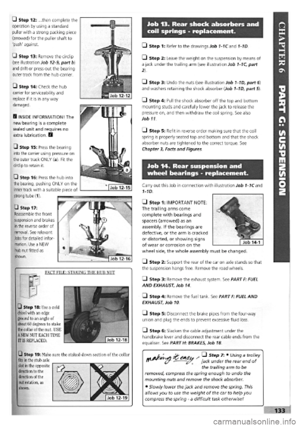
Q Step 12: ...then complete the
operation by using a standard
puller with a strong packing piece
(arrowed) for the puller shaft to
'push' against.
G Step 13: Remove the circlip
(see illustration Job
12-9,
part b)
and drift or press out the bearing
outer track from the hub carrier.
• Step 14: Check the hub
carrier for serviceability and
replace if it is in any way
damaged.
D INSIDE INFORMATION! The
new bearing is a complete
sealed unit and requires no
extra lubrication. D
• Step 15: Press the bearing
into the carrier using pressure on
the outer track ONLY (a). Fit the
circlip to retain it.
• Step 17:
Reassemble the front
suspension and brakes
in
the reverse order of
removal. See relevant
Jobs
for detailed infor-
mation. Use a NEW
hub nut fitted as
shown.
FACT FILE: STAKING THE HUB NUT
• Step 18: Use a cold
chisel
with an edge
ground to an angle of
about 60 degrees to stake
the
collar of the nut. USE
A
NEW NUT EACH TIME
IT IS REPLACED.
Q Step 19: Make sure the staked-down section of the collar
fits
in the stub axle
slot
in the opposite
direction to the
direction of the
nut
rotation, as
shown.
• Step 1: Refer to the drawings Job 1-1Cand 1-1D.
• Step 2: Leave the weight on the suspension by means of
a jack under the trailing arm (see illustration Job
1-1C,
part
• Step 3: Undo the nuts (see illustration Job
1-1D,
part
6)
and washers retaining the shock absorber (Job
1-1D,
part 5).
• Step 4: Pull the shock absorber off the top and bottom
mounting studs and carefully lower the jack to release the
pressure on, and then withdraw the coil spring. See also
Job 11
O Step 5: Refit in reverse order making sure that the coil
spring is properly seated top and bottom and that the shock
absorber nuts are tightened to the correct torque. See
Chapter
3,
Facts and Figures.
Job 14. Rear suspension and
wheel bearings - replacement.
Carry out this Job in connection with illustration Job
1-1C
and
1-1D.
• Step 1: IMPORTANT NOTE:
The trailing arms come
complete with bearings and
spacers (arrowed) as an
assembly. If the bearings are
defective, or the arm is cracked
or distorted, or showing signs
of wear or corrosion on the
wheel side, the whole assembly must be changed.
Q Step 2: Support the rear of the car on axle stands so that
the suspension hangs free. Remove the road wheels.
• Step 3: Remove the exhaust system. See PART F: FUEL
AND EXHAUST, Job 14.
• Step 4: Remove the fuel tank. See PART F: FUEL AND
EXHAUST, Job 10
• Step 5: Disconnect the brake pipes from the four-way
union and plug the ends to prevent excessive fluid loss.
Q Step 6: Slacken the cable adjustment under the
handbrake lever and disconnect the rear cable ends from the
equaliser. See PART H: BRAKES, Job 18
/ • Step 7: • Using a trolley
jack under the rear end of
the trailing arm to be
removed, compress the spring enough to undo the
mounting nuts and remove the shock absorber.
• Slowly lower the jack and remove the spring. This
allows you to use the weight of the car to help you
compress the spring
-
a difficult task otherwise!
Q Step 16: Press the hub into
the bearing, pushing ONLY on the
inner track with a suitable piece of
strong tube (1).
Page 136 of 171
Job 13. Pressure regulating
valves, ABS system - replacement
and adjustment.
Job 14. RPM sensors, ABS
systems - replacement.
H INSIDE INFORMATION! The RPM sensors align with
the flywheels (which look like toothed rings) and which
rotate with the road wheels. The sensors measure the
vehicle's running speed, acceleration, deceleration and
wheel creep. These signals are sent to the electronic
control unit and allow it to instruct the hydraulic control
unit to vary the brake fluid pressure to each wheel as
necessary to prevent the brakes from locking up. E3
• Step 1: This
is the position of
the front wheel
sensor (a)...
• Step 2: ...and
this is the position
of the rear wheel
sensor (arrowed).
H INSIDE INFORMATION! FIAT advise that no adjust-
ments can be made, so, if the gap is outside these values,
clean and check the condition and the seating of the
sensor and the condition of the flywheel. D
L_l Step 4: To remove the sensor, undo the fixing screw and
withdraw the sensor from its housing, then trace the wire to
the connector and unplug it.
• Step 5: Clean round the housing and fit the new sensor,
ensuring that it is properly seated.
O Step 6: Secure the wire along its route to the connector
and plug in.
• Step 1: Position the car over a pit or on a lift with the
weight still on the wheels. Locate the valves
-
one on each
suspension trailing arm.
• Step 2: Undo
the brake pipe
unions (a) using
(preferably) a split
ring spanner and
plug the ends of
the pipes. Remove
the two upper
securing bolts
shown here
• Step 3: Take out the
lower two bolts and
remove the valve.
• Step 4: Install the
new valve and connect
the brake pipes.
• Step 5: With the car
at its normal weight
including spare wheel
and fuel, add a load of 50
kg to the boot as far
forward as possible.
• Step 6:
• Loosen the
bracket fixing bolt
(1).
• Hang a weight
of 2 kg from the
bracket eye (2).
• Keep the
bracket in this
position while you
tighten and lock
the fixing bolt (1).
Q Step 7: Repeat this adjustment on the other side to
ensure equal braking.
• Step 8: Bleed the brakes. See Job
17
• Step 3:
Check the gap
between the end
of each sensor and the flywheel, at the front (see illustration
Job
14-1,
part b) and at the rear. The correct gap should be:
• 1400/1600 petrol
-
between 0.62 and 1.35 mm, both front
and rear.
• 1900 turbo Diesel
-
between 0.225 and 0.925 mm for the
fronts and between 0.13 and 1.27 mm for the rears.
Page 139 of 171

PART I: BODY AMD INTERIOR
PART 1: Contents
Job 1. Bonnet
-
removal and refitting. Job 8. Tempra boot lid locking mechanism
-
removal and
Job 2. Bonnet locking mechanism
-
replacement and refitting.
adjustment. Job 9. Front bumper and grille
-
removal and refitting.
Job 3. Radiator grille
-
removal and refitting. Job 10. Rear bumper
-
removal and refitting.
Job 4. Tipo/Tempra tailgate
-
removal and refitting. Job 11. Door trim panel
-
removal and refitting.
Job 5. Tipo tailgate locking mechanism
-
removal and Job 12. Door component
-
removal and replacement
refitting. Job 13. Door removal, replacement and adjustment.
Job 6. Tempra estate tailgate locking mechanism
-
removal Job 14. Door mirror
-
replacement.
and refitting. Job 15. Sun roof
-
removal and refitting.
Job 7. Tempra boot lid
-
removal and refitting. Job 16. Front seats
-
removal and refitting.
-Job 17. Rear seats
-
removal and refitting.
Job 1. Bonnet - removal and
refitting.
Job 2. Bonnet locking mechanism
- replacement and adjustment.
• Step 1: Note the bonnet hinges, support and stops.
G Step 2: Use the prop and hold the bonnet open. Outline
the hinge positions on the bonnet with masking tape for
accurate refitment.
G Step 3: Ask an assistant to support the bonnet. Undo the
two hinge fixing bolts. Carefully lift the bonnet clear.
if refitting the bonnet, put a
piece of cloth under each
rear corner to protect the bodywork.
• Step 1: This drawing shows left and right hand drive
layouts. Select which is right for your car.
• Step 2: The two screws (illustration Job 2-3 arrowed)
used to fix the locking pin/safety catch assembly to the bonnet
are also used for fore and aft adjustment. This is best done a
little at a time until smooth operation is achieved.
• Step 3: Height
adjustment (levelling with
the wings) is achieved by
screwing the bump stops
(inset, arrowed) up or
down. Then slacken the
G Step 5: When refitting, tighten the bolts just enough to
grip the hinges, then carefully lower the bonnet to check for
correct alignment all round
-
equal gapping.
When the alignment is satisfactory, tighten the bolts to their
correct torque, See Chapter 3, Facts and Figures
[G Step 4: To remove the lock/striker assembly, separate the
cable eyelet from the operating lever hook, see illustration Job
2-1, parts 13 and 14
1 - lock/striker assembly, front panel 2 - locking pin/safety catch, bonnet 3 - release lever. (Also fitted other side, some R/H drive cars) 4 - cable, L/H drive 5 - cable, R/H drive
and secondary cable, R/H drive 7 - screw 8
-
washer 9 - bolt 10 - bolt
11 - cable clip 12 - cable fixing screw 13 - cable eyelet 14 - operating lever hook Job 2-1
locking nut (hidden
behind the locking pin
spring) and screw the
locking pin up or down
until the bonnet will shut
when dropped from 30 cm height and then have no
movement on the lock. Don't forget to tighten the locknut.