1988 CITROEN CX check oil
[x] Cancel search: check oilPage 261 of 648

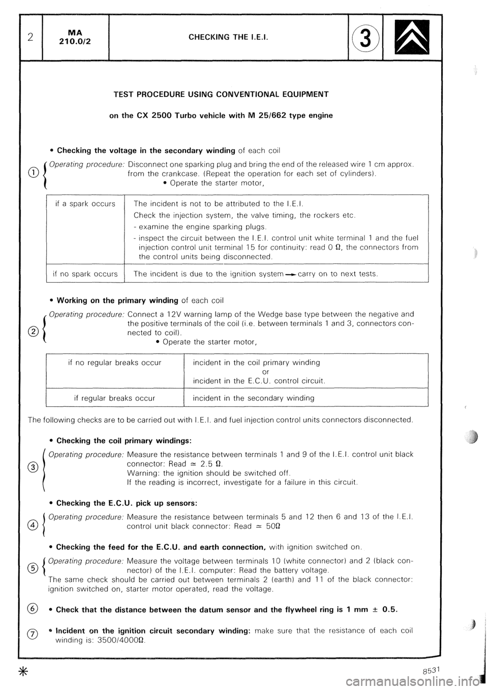
CHECKING THE I.E.I.
TEST PROCEDURE USING CONVENTIONAL EQUIPMENT
on the CX 2500 Turbo vehicle with M 25/662 type engine
0 Checking the voltage in the secondary winding of each coil
0 Operating procedure: Disconnect one sparking plug and bring the end of the released wire 1 cm approx
from the crankcase. (Repeat the operation for each set of cylinders).
0 Operate the starter motor,
if a spark occurs
if no spark occurs The incident is not to be attributed to the I.E.I.
Check the injection system, the valve timing, the rockers etc.
- examine the engine sparking plugs.
- inspect the circuit between the I.E.I. control unit white terminal 1 and the fuel
injection control unit terminal 15 for continuity: read 0 Q, the connectors from
the control units being disconnected.
The incident is due to the ignition system-carry on to next tests.
l Working on the primary winding of each coil
Operating procedure: Connect a 12V warning lamp of the Wedge base type between the negative and
the positive terminals of the coil (i.e. between terminals 1 and 3, connectors con-
netted to coil).
l Operate the starter motor,
if no regular breaks occur incident in the coil primary winding
or
incident in the E.C.U. control circuit.
if regular breaks occur incident in the secondary winding
The following checks are to be carried out with I.E.I. and fuel injection control units connectors disconnected.
0 Checking the coil primary windings:
Operating procedure: Measure the resistance between terminals 1 and 9 of the I.E.I. control unit black
0 connector: Read = 2.5 Q.
Warning: the ignition should be switched off.
If the reading is incorrect, investigate for a failure in this circuit.
l Checking the E.C.U. pick up sensors:
OI Operating procedure: Measure the resistance between terminals 5 and 12 then 6 and 13 of the I.E.I.
4
control unit black connector: Read 2: 5OQ
0 Checking the feed for the E.C.U. and earth connection, with ignition switched on.
d 5 Operating procedure: Measure the voltage between terminals 10 (white connector) and 2 (black con-
nectar) of the I.E.I. computer: Read the battery voltage.
The same check should be carried out between terminals 2 (earth) and 11 of the black connector:
ignition switched on, starter motor operated, read the voltage.
@ 0 Check that the distance between the datum sensor and the flywheel ring is 1 mm + 0.5.
0 * Incident on the ignition circuit secondary winding: make sure that the resistance of each coil
winding is: 350014OOOQ.
Page 264 of 648

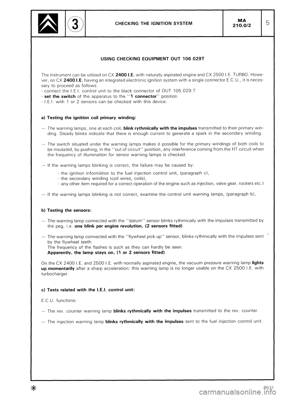
CHECKING THE IGNITION SYSTEM
USING CHECKING EQUIPMENT OUT 106 029T
The instrument can be utilised on CX 2400 I.E. with naturally aspirated engine and CX 2500 I.E. TURBO. Howe-
ver, on CX 2400 I.E. having an integrated electronic ignition system with a single connector E.C.U., it is neces-
sary to proceed as follows:
- connect the I.E.I. control unit to the black connector of OUT 105 029.T
- set the switch of the apparatus to the “1 connector” position
- I.E.I. with 1 or 2 sensors can be checked with this device.
a) Testing the ignition coil primary winding:
- The warning lamps, one at each coil, blink rythmically with the impulses transmitted to their primary win-
ding. Steady blinks indicate that there is enough current to generate a spark in the secondary winding.
- The switch situated under the warning lamps makes it possible for the primary windings of both coils to
be insulated, by pushing, in the “out of circuit“ position, any interference coming from the HT circuit when
the frequency of illumination for sensor warning lamps is checked.
- If the warning lamps blinking is correct, the failure may be caused by:
- the ignition information to the fuel injection control unit, (paragraph c),
- the secondary winding (coil wires, coils),
- any other item required for a correct operation of the engine such as injection, valve gear, rockers etc.) -
If the warning lamps blinking is not correct, examine the control unit warning lamps, (paragraph b),
b) Testing the sensors: -
The warning lamp connected with the “datum” sensor blinks rythmically with the impulses transmitted by
the peg, i.e. one blink per engine revolution, (2 sensors fitted).
- The warning lamp connected with the “flywheel pick up” sensor, blinks rythmically with the impulses sent ’
by the flywheel teeth.
The frequency of the flashes is such as they can hardly be seen.
Apparently, the lamp stays on, (1 or 2 sensors fitted).
On the CX 2400 I.E. and 2500 I.E. with normally aspirated engine, the vacuum pressure warning lamp lights
up momentarily after a sharp acceleration: this warning lamp is no longer usable on the CX 2500 I.E. with
turbocharger.
c) Tests related with the I.E.I. control unit:
E.C.U. functions: -
The rev. counter warning lamp blinks rythmically with the impulses transmitted to the rev. counter.
- The injection warning lamp blinks rythmically with the impulses sent to the fuel injection control unit
+k 8531
Page 318 of 648

REPAIR OF THE HYDRAULIC SYSTEM
FITTING PRECAUTIONS
PRECAUTIONS TO BE TAKEN WHEN WORKING ON
THE HYDRAULIC UNITS OR THE SYSTEM
The correct functioning of the entire system presupposes perfect cleanliness of the fluid and the hydraulic
units. Stringent precaut!ons must therefore be taken when working on the hydraulic system and during the
storage of the fluid and components. 1. HYDRAULIC FLUID:
Mineral hydraulic fluid (LHM) is the only suitable type and must be used to the exclusion of all others in the hydrau-
lic system of the car.
This LHM fluid is green in co/our and similar to engine oil.
The use of any other would ruin the rubber rings and seals in the system. 2. RUBBER UNITS AND PARTS:
Suitable components are identified by their green co/our and may only be replaced by genuine replacement
components painted or marked in green.
All rubber components (seals, hoses, diaphragm, etc...) are of a special quality for use with LHM fluid and are
identified by their white or green colour. 3. STORAGE:
Components must be stored, full of fluid and blanked off. Like the piping, they must be protected against shock
and the ingress of dust.
Rubber tubing and joints must be stored away from dust, air, light and heat.
LHM hydraulic fluid must be stored in its original containers carefully sealed. We advise the use of one litre (for
topping up) or five litre cans (for refilling) to avoid having to keep opened containers. 4. CHECKS BEFORE CARRYING OUT WORK:
Before-working on the hydraulic system in case of faulty operation, ensure the following:
a) That the controls or the mechanical linkages of the units or the group of hydraulic units involved are
not stiff in operation
I I
b) and that the HP circuit is under pressure, as follows:
With the engine at idling speed:
- Unscrew the pressure-release screw on the pressure regulator by one turn to one turn and a half: a sound
of leakage should be heard from the regulator.
- Retighten the release screw: cut-out must occur which results in a reduction in the running noise emitted
by the H.P. pump.
If not, check in the following sequence:
- that there is sufficient fluid in the reservoir,
- that the reservoir filter is clean and in good condition,
- that the H.P. pump is primed and there is no air leak on the suction side of the pump,
- that the release screw of the pressure regulator is correctly tightened,
- that sealing ball (2) is in position, (see Fig. I and II, page 5).
Page 319 of 648

REPAIR OF THE HYDRAULIC SYSTEM
FITTING PRECAUTIONS
5. PRECAUTIONS TO BE TAKEN BEFORE WORKING ON THE HYDRAULIC SYSTEM:
a) Carrefully clean the aera of work, the unions and the unit to be removed
- Disconnect the lead from the negative terminal of the battery.
- Only use petrol or lead-free petrol cleaning.
b) Release the pressure in the circuits:
- Place the vehicle in the K/OW~~ position.
- Slacken the pressure regulator release screw (by one turn to one turn and a half, do not remove the screw:
the sealing ball (21, see Fig. I and II page 5, could get lost,
- Wait until the front of the car has reached the low position. 6. PRECAUTIONS TO BE TAKEN DURING REMOVAL.
a) Blank off the metal pipes with plugs, and rubber tubes with round pins of the correct diameter
b) Blank off the openings of components with plugs of the correct diameter.
NOTE: Plugs and pins must be carefully cleaned before insertion 7. CHECK OR TEST OF HYDRAULIC UNITS:
- use 4034-T test bench equipped and designed for use with LHM fluid.
- This bench is painted green and its accessories are marked in green.
- Never use the bench with another fluid or for testing components operating with another fluid (units of a c(D))
car using LHS 2 for instance).
NOTE: The uLe Bozec)) pump used on test benches for checking DIESEL injectors can be resorted to for testing,
components operating with LHM mineral fluid provided that the bench is cleaned first. 8. PRECAUTIONS TO BE TAKEN DURING REFITTING.
a 1 Cleaning:
- steel pipes must be blown through with compressed air,
- rubber tubes and seals must be washed in petrol or lead-free petrol and then dried with compressed air,
- hydraulic units must also be cleaned with petrol or lead-free petrol and blown through with compressed air.
NOTE: Renew all joints and seals during refitting
b) Lubrication.
- Follow the indications as stated in the operations in the Manual.
- Joints and internal parts must be lightly oiled before fitting (use mineral fluid LHM only).
- If parts in contact with hydraulic units have to be greased, use a mineral grease only (as employed for cardan
shafts or bearings). +#+
8531-8532