Page 147 of 962

Fuel Pulp
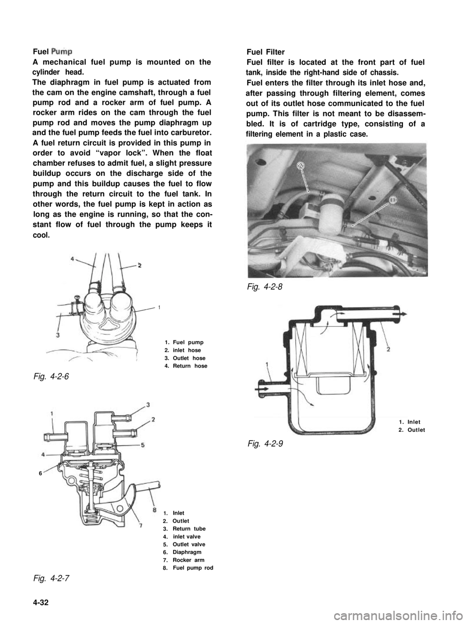
A mechanical fuel pump is mounted on the
cylinder head.
The diaphragm in fuel pump is actuated from
the cam on the engine camshaft, through a fuel
pump rod and a rocker arm of fuel pump. A
rocker arm rides on the cam through the fuel
pump rod and moves the pump diaphragm up
and the fuel pump feeds the fuel into carburetor.
A fuel return circuit is provided in this pump in
order to avoid “vapor lock”. When the float
chamber refuses to admit fuel, a slight pressure
buildup occurs on the discharge side of the
pump and this buildup causes the fuel to flow
through the return circuit to the fuel tank. In
other words, the fuel pump is kept in action as
long as the engine is running, so that the con-
stant flow of fuel through the pump keeps it
cool.
2
Fig. 4-2-8
Fig. 4-2-6
Fuel Filter
Fuel filter is located at the front part of fuel
tank, inside the right-hand side of chassis.
Fuel enters the filter through its inlet hose and,
after passing through filtering element, comes
out of its outlet hose communicated to the fuel
pump. This filter is not meant to be disassem-
bled. It is of cartridge type, consisting of a
filtering element in a plastic case.
1
1. Fuel pump
2. inlet hose
3. Outlet hose4. Return hose
6
1. Inlet
2. Outlet
Fig. 4-2-9
1.Inlet
2.Outlet
3.Return tube
4.inlet valve
5.Outlet valve
6.Diaphragm
7.Rocker arm
8.Fuel pump rod
Fig. 4-2-7
4-32
Page 149 of 962
![SUZUKI GRAND VITARA 1987 Service Repair Manual ,Fuel Pump
[ Rem’oval]
1) Disconnect negative cable from battery.
2) Remove fuel filler cap from fuel filler neck to
release fuel vapor pressure in fuel tank. After
releasing, reinstall the cap.
3) SUZUKI GRAND VITARA 1987 Service Repair Manual ,Fuel Pump
[ Rem’oval]
1) Disconnect negative cable from battery.
2) Remove fuel filler cap from fuel filler neck to
release fuel vapor pressure in fuel tank. After
releasing, reinstall the cap.
3)](/manual-img/20/57437/w960_57437-148.png)
,Fuel Pump
[ Rem’oval]
1) Disconnect negative cable from battery.
2) Remove fuel filler cap from fuel filler neck to
release fuel vapor pressure in fuel tank. After
releasing, reinstall the cap.
3) Disconnect fuel inlet, outlet and return hoses
from fuel pump.
Fuel Filter
[Removal]
1) Disconnect negative cable from battery.
2) Remove fuel filler cap to release fuel vapor
pressure in fuel tank. After releasing, reinstall
the cap.
3) Disconnect inlet and outlet hoses from fuel
filter.
4) Remove fuel filter with clamp.
[Installation]
1) Install filter and clamp, and connect inlet
and outlet hoses to fuel filter.
NOTE:.
The top connection is for outlet hose, the
lower one for inlet hose.
1. Fuel pump
2. Inlet hose3. Outlet hose
4. Return hose
Fig. 4-2-l 1
4) Remove fuel pump from cylinder head.
5) Remove fuel pump rod from cylinder head.
2
1. Fuel pump rod
2. Cylinder head
[Installation]
Reverse removal procedure for installation
using care for the following.
l After oiling it,install fuel pump rod to
cylinder head.
0 Use new fuel pump gasket.
l Make sure for proper hose connection.
0 Upon completion of installation, start engine
and check fuel hose or its joints for leaks.
1.Fuel filter3.From fueltank
2.To fuel pump4.Clamp
Fig.4-2-13
2) Connect negative cable to battery.
3) After installation, start engine and check it
for leaks.
Fuel Tank
[Removal]
1) Disconnect negative cable from battery.
2) Disconnect fuel level gauge lead wire.
3) To release the pressure in fuel tank, remove
fuel filler cap and then, reinstall it.
4) Raise car on hoist.
5) Drain fuel by removing drain plug.
6) Remove filler hose protector.
7) Disconnect filler hose from fuel tank.
.8) Disconnect fuel hosesand pipe from fuel tank.
9) Remove fuel tank.
4-34
Page 171 of 962

NOTE:
l To check therm0 sensor for operation at
higher than 40°C (104” F) temperature when
therm0 sensor is lower than 25°C (77” F),
remove therm0 sensor from air cleaner cap
and warm it up with hair drier or photo light
before checking.
l Never touch bimetal or valve in therm0
sensor.
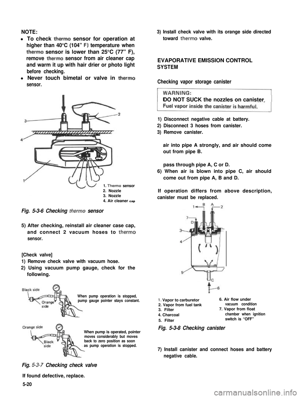
1. Therm0 sensor
2. Nozzle3. Nozzle
4. Air cleaner cap
Fig. 5-3-6 Checking therm0 sensor
5) After checking, reinstall air cleaner case cap,
and connect 2 vacuum hoses to therm0
sensor.
[Check valve]
1) Remove check valve with vacuum hose.
2) Using vacuum pump gauge, check for the
following.
When pump operation is stopped,pump gauge pointer stays constant.
When pump is operated, pointermoves considerably but movesback to zero position as soonas pump operation is stopped.
Fig. 5-3-7 Checking check valve
If found defective, replace.
3) Install check valve with its orange side directed
toward therm0 valve.
EVAPORATIVE EMISSION CONTROL
SYSTEM
Checking vapor storage canister
DO NOT SUCK the nozzles on canister
1) Disconnect negative cable at battery.
2) Disconnect 3 hoses from canister.
3) Remove canister.
air into pipe A strongly, and air should come
out from pipe B.
pass through pipe A, C or D.
6) When air is blown into pipe C, air should
come out from pipe A, B and D.
If operation differs from above description,
canister must be replaced.
1. Vapor to carburetor6. Air flow under
2. Vapor from fuel tankvacuum condition
3. Filter7. Vapor from float
4. Charcoalchamber when ignition
5. Filterswitch is “OFF”
Fig. 5-3-8 Checking canister
7) Install canister and connect hoses and battery
negative cable.
5-20
Page 473 of 962

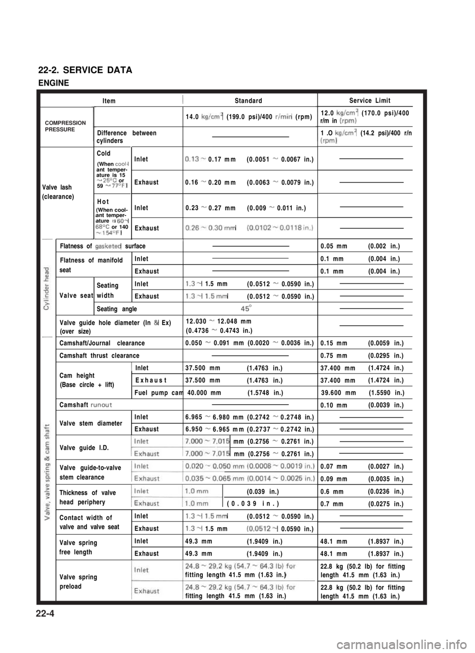
22-2. SERVICE DATA
ENGINE
ItemStandardService Limit
12.0 kg/cm2 (170.0 psi)/400r/m in (rpm)
1 .O kg/cm2 (14.2 psi)/400 r/n
(m-d
14.0 kg/cm2 (199.0 psi)/400 r/min (rpm)
Difference betweencylinders
Cold
(When cooi-ant temper-ature is 15- 25T or59 - 77OF)
Hot
(When cool-ant temper-ature IS 60-68T or 140-154OFJ
Valve lash
(clearance)
Inlet
Exhaust
Inlet
Exhaust
0.13-0.17mm(0.0051 - 0.0067 in.)
0.16 -0.20mm(0.0063 - 0.0079 in.)
0.23 -0.27mm(0.009 - 0.011 in.)
0.26%0.30mm (0.0102-0.0118in.)
/0.05 mm(0.002 in.)Flatness of gasketed surface
Flatness of manifoldInlet
seatExhaust
SeatingInlet
Valve seat widthExhaust
Seating angle
1.3- 1.5 mm(0.0512 - 0.0590 in.)
1.3- 1.5mm(0.0512 - 0.0590 in.)
45O
0.1 mm(0.004 in.)
0.1 mm(0.004 in.)
Valve guide hole diameter (In & Ex)12.030 - 12.048 mm
(over size)(0.4736 - 0.4743 in.)
Camshaft/Journal clearance0.050 - 0.091 mm (0.0020 - 0.0036 in.)0.15 mm(0.0059 in.)
0.75 mm(0.0295 in.)Camshaft thrust clearance
1 Inlet37.500 mm(1.4763 in.)37.400 mm(1.4724 in.)Cam heightI
(Base circle + lift) Exhaust37.500 mm(1.4763 in.)
Fuel pump cam 40.000 mm(1.5748 in.)
37.400 mm(1.4724 in.)
39.600 mm(1.5590 in.)
Camshaft runout0.10 mm(0.0039 in.)
Inlet6.965-6.980mm(0.2742-0.2748in.)Valve stem diameterExhaust6.950-6.965mm(0.2737-0.2742in.)
Valve guide I.D.7.000 - 7.015 mm (0.2756 - 0.2761 in.)
w.015 mm (0.2756 - 0.2761 in.)
Valve guide-to-valve
stem clearance
0.07 mm(0.0027 in.)
0.09 mm(0.0035 in.)
Thickness of valve(0.039 in.)
head peripherymw (0.039 in.)
0.6 mm(0.0236 in.)
0.7 mm(0.0275 in.)
Contact width ofInlet1.3- 1.5mm(0.0512 - 0.0590 in.)
valve and valve seatExhaust1.3- 1.5 mm(0.0512- 0.0590 in.)
48.1 mm(1.8937 in.)Valve spring
free length
Inlet
Exhaust
49.3 mm(1.9409 in.)
49.3 mm(1.9409 in.)48.1 mm(1.8937 in.)
Valve spring
preload
fitting length 41.5 mm (1.63 in.)
fitting length 41.5 mm (1.63 in.)
22.8 kg (50.2 lb) for fitting
length 41.5 mm (1.63 in.)
22.8 kg (50.2 lb) for fitting
length 41.5 mm (1.63 in.)
COMPRESSIONPRESSURE
22-4