1987 SUZUKI GRAND VITARA fuel pump
[x] Cancel search: fuel pumpPage 117 of 962
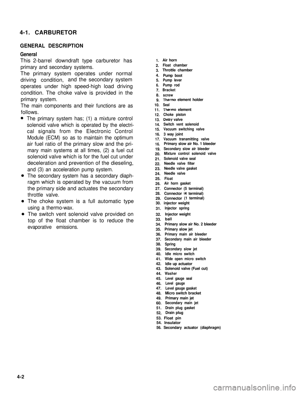
4-1. CARBURETOR
GENERAL DESCRIPTION
General
This 2-barrel downdraft type carburetor has
primary and secondary systems.
The primary system operates under normal
driving condition,and the secondary system
operates under high speed-high load driving
condition. The choke valve is provided in the
primary system.
The main components and their functions are as
follows.
The primary system has; (1) a mixture control
solenoid valve which is operated by the electri-
cal signals from the Electronic Control
Module (ECM) so as to maintain the optimum
air fuel ratio of the primary slow and the pri-
mary main systems at all times, (2) a fuel cut
solenoid valve which is for the fuel cut under
deceleration and prevention of the dieseling,
and (3) an acceleration pump system.
The secondary system has a secondary diaph-
ragm which is operated by the vacuum from
the primary side and actuates the secondary
throttle valve.
The choke system is a full automatic type
using a thermo-wax.
The switch vent solenoid valve provided on
top of the float chamber is to reduce the
evaporative emissions.
1.Air horn
2.Float chamber
3.Throttle chamber
4.Pump boot5.Pump lever
6.Pump rod
7.Bracket
8.screw
9.Therm0 element holder
10.Seal
11.Therm0 element
12.Choke piston
13.Delay valve
14.Switch vent solenoid
15.Vacuum switching valve
16.3 way joint
17.Vacuum transmitting valve
16.Primary slow air No. 1 bleeder
19.Secondary slow air bleeder
20.Mixture control solenoid valve
21.Solenoid valve seal
22.Needle valve filter
23.Needle valve gasket
24.Needle valve
25.Float
26.Air horn gasket
27.Connector (5 terminal)
28.Connector (4 terminal)
29.Connector (1 terminal)
30. injector weight
31.Injector spring
32.Injector weight
33.
34.Primary slow air No. 2 bleeder
35.Primary slow jet
36.Primary main air bleeder
37.Secondary main air bleeder
38.Spring
39.Secondary slow jet
40.Idle micro switch
41.Wide open micro switch
42.Idle up actuator43.Solenoid valve (Fuel cut)
44.Washer
45.Level gauge seal
46.Level gauge
47.Level gauge gasket
48.Micro switch bracket
49.Primary main jet
60.Secondary main jet
51.Drain plug gasket
52,Drain plug
53. Float pin54. Insulator56. Secondary actuator (diaphragm)
4-2
ball
Page 120 of 962
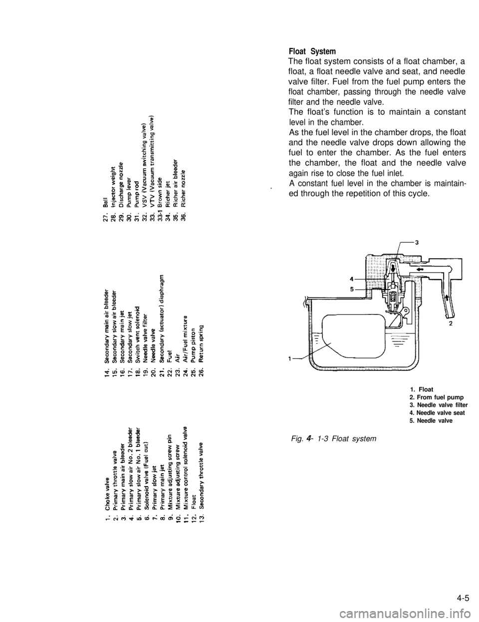
Float System
The float system consists of a float chamber, a
float, a float needle valve and seat, and needle
valve filter. Fuel from the fuel pump enters the
float chamber, passing through the needle valve
filter and the needle valve.
The float’s function is to maintain a constant
level in the chamber.
As the fuel level in the chamber drops, the float
and the needle valve drops down allowing the
fuel to enter the chamber. As the fuel enters
the chamber, the float and the needle valve
again rise to close the fuel inlet.
A constant fuel level in the chamber is maintain-.ed through the repetition of this cycle.
1. Float
2. From fuel pump3. Needle valve filter
4. Needle valve seat
5. Needle valve
Fig. 4- 1-3 Float system
4-5
Page 124 of 962
![SUZUKI GRAND VITARA 1987 Service Repair Manual [Secondary main system]
Operation of the secondary throttle valve is also
controlled by the VTV and VSV. When the VSV
is closed, the vacuum to be applied to the
secondary diaphragm passes the VTV side SUZUKI GRAND VITARA 1987 Service Repair Manual [Secondary main system]
Operation of the secondary throttle valve is also
controlled by the VTV and VSV. When the VSV
is closed, the vacuum to be applied to the
secondary diaphragm passes the VTV side](/manual-img/20/57437/w960_57437-123.png)
[Secondary main system]
Operation of the secondary throttle valve is also
controlled by the VTV and VSV. When the VSV
is closed, the vacuum to be applied to the
secondary diaphragm passes the VTV side and
the secondary throttle valve opens gradually.
When the primary throttle valve opens almost
fully, the VSV opens according to the signal
from the ECM. Then the vacuum is applied
directly to the secondary diaphragm and the
secondary throttle valve responds to intensity of
vacuum. When the secondary throttle valve open-
ing is wider than when secondary slow system
operates, the fuel is discharged through the
secondary main jet and mixed with the air from
the secondary main air bleeder. The air/fuel
mixture is discharged into the carburetor bore
through the main discharge hole.
1. Secondary main jet2. Secondary main air bleeder
3. Main discharge hole4. Primary throttle valve
5. Secondary throttle valve
6.Secondarydiaphragm7.VTV
8.VSV
Acceleration Pump System
This system operates to supply extra fuel to the
primary side only during the acceleration.
When the primary throttle valve closes, the
return spring pushes up the pump piston. Then
the fuel pushes up the check ball and enters into
the pump cylinder. When the throttle valve opens
during the acceleration, simultaneously the
pump piston is pushed down by means of the
pump lever. Then the fuel in the pump cylinder
pushes up the discharge ball and the lower
injector weight and discharges into the carbure-
tor bore from the pump discharge nozzle.
In this way, a higher acceleration performance is
provided by this system.
1. Primary throttle valve
2.Return spring3.Pump piston
4.Check ball6.Pump cylinder
6.Plunger7.Pump lever8.Discharge ball
9.Injector weight10. Pump discharge nozzle11. Pump damper spring
Fig. 4- l- 10Acceleration pump s ys tern
Fig. 4-l-9 Secondary main system
4-9
Page 128 of 962
0 Connect electric couplers securely.
l Connect accelerator cable to carburetor. With
the accelerator pedal released, adjust the cable
play to specification. This adjustment can be
made by turning the adjusting nut. After
adjustment, tighten the lock nut. Refer to
p. 4-19.
l Connect vacuum hoses securely.
l Refill cooling system.
l Connect negative cable at battery.
NOTE:
Upon completion of installation, be sure to
check each part for evidence of fuel leakage and
for proper operation. If defective, correct..
UNIT REPAIR OVERHAUL
This section outlines procedure to be used for
overhauling carburetor as removed from engine.
For removal and installation of carburetor from
and to engine, refer to the previous page.
NOTE:
l Be sure to replace gaskets as well as worn or
damaged parts.
l While disassembling and assembling carbure-
tor, use special care not to deform levers on
throttle valve shaft or cause damage to any
other parts.
l Don’t disassemble mixture control solenoid
valve and accelerator pump piston.
l Don’t remove idle and wide open micro
switches from the bracket where they are
installed.
Disassembly
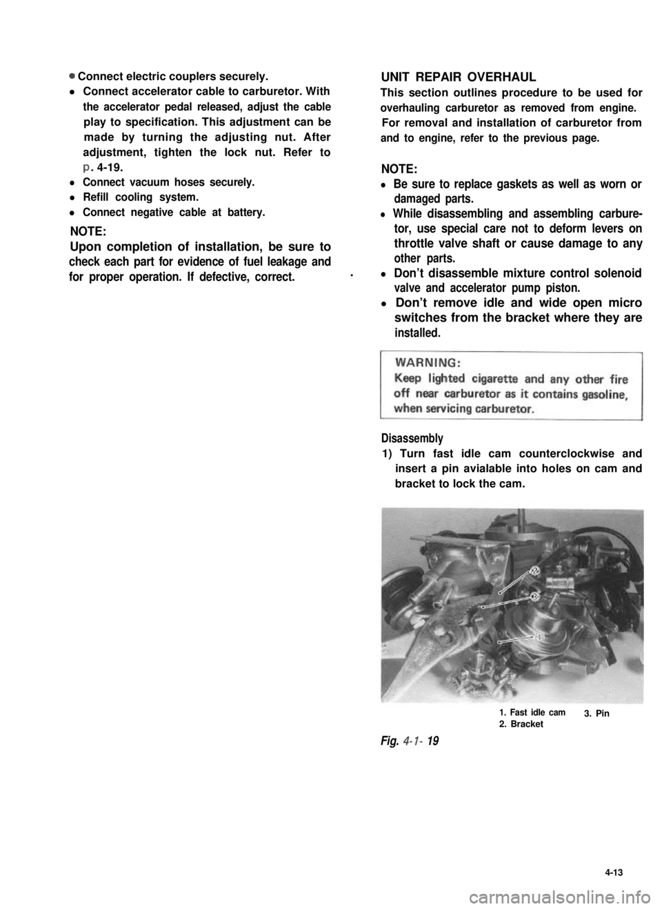
1) Turn fast idle cam counterclockwise and
insert a pin avialable into holes on cam and
bracket to lock the cam.
Fig. 4- I- 19
1. Fast idle cam
2. Bracket3. Pin
4-13
Page 130 of 962
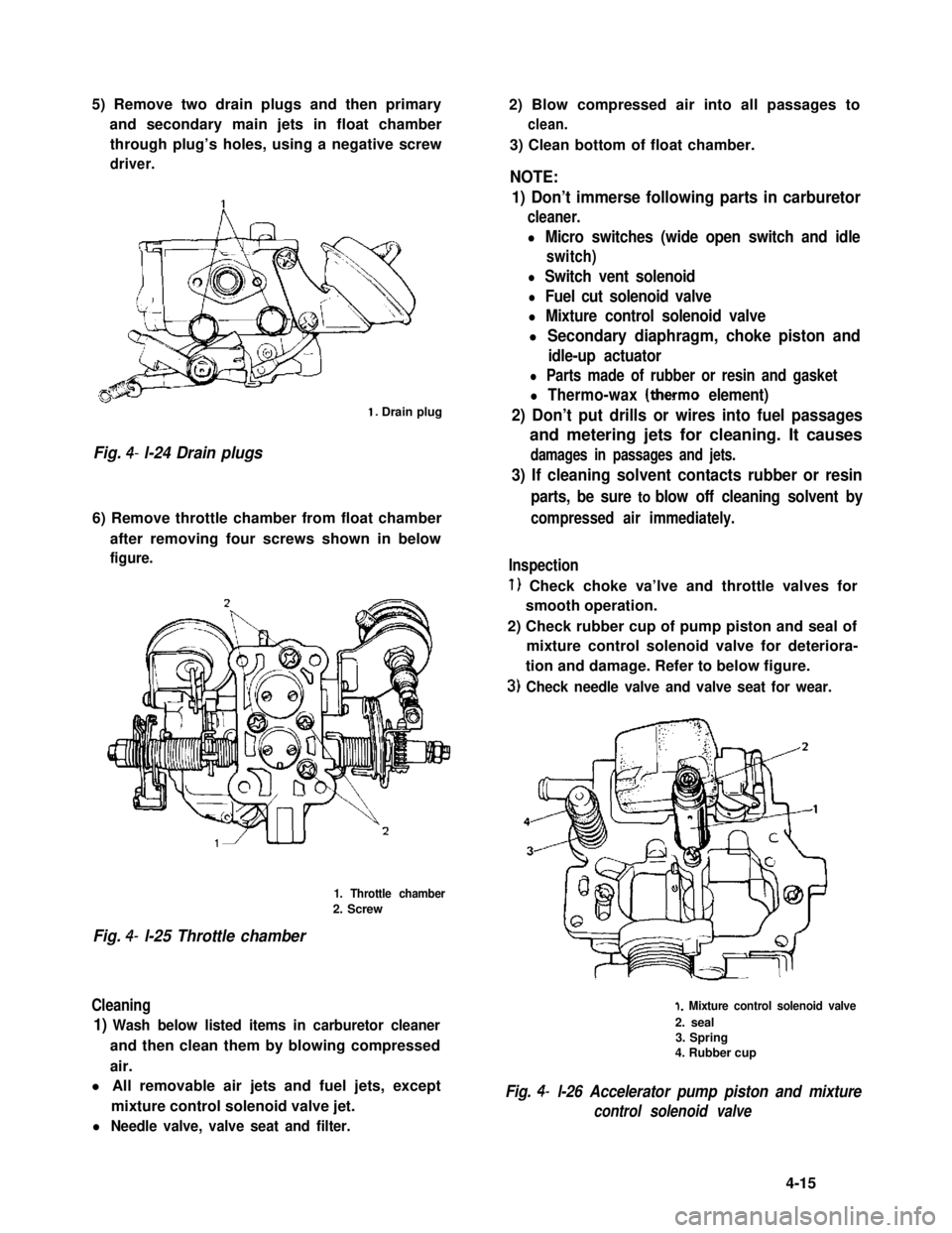
5) Remove two drain plugs and then primary
and secondary main jets in float chamber
through plug’s holes, using a negative screw
driver.
1. Drain plug
Fig. 4- l-24 Drain plugs
6) Remove throttle chamber from float chamber
after removing four screws shown in below
figure.
1. Throttle chamber
2. Screw
Fig. 4- l-25 Throttle chamber
Cleaning
1) Wash below listed items in carburetor cleaner
and then clean them by blowing compressed
air.
l All removable air jets and fuel jets, except
mixture control solenoid valve jet.
l Needle valve, valve seat and filter.
2) Blow compressed air into all passages to
clean.
3) Clean bottom of float chamber.
NOTE:
1) Don’t immerse following parts in carburetor
cleaner.
l Micro switches (wide open switch and idle
switch)
l Switch vent solenoid
l Fuel cut solenoid valve
l Mixture control solenoid valve
l Secondary diaphragm, choke piston and
idle-up actuator
l Parts made of rubber or resin and gasket
l Thermo-wax (therm0 element)
2) Don’t put drills or wires into fuel passages
and metering jets for cleaning. It causes
damages in passages and jets.
3) If cleaning solvent contacts rubber or resin
parts, be sure to blow off cleaning solvent by
compressed air immediately.
Inspection
1) Check choke va’lve and throttle valves for
smooth operation.
2) Check rubber cup of pump piston and seal of
mixture control solenoid valve for deteriora-
tion and damage. Refer to below figure.
3) Check needle valve and valve seat for wear.
1. Mixture control solenoid valve
2. seal3. Spring4. Rubber cup
Fig. 4- l-26 Accelerator pump piston and mixture
control solenoid valve
4-15
Page 140 of 962
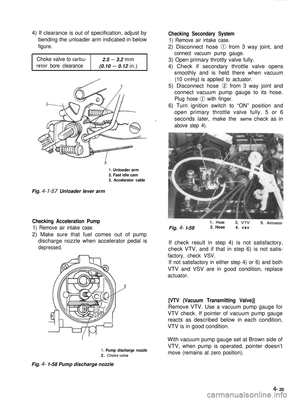
4) If clearance is out of specification, adjust by
bending the unloader arm indicated in belowfigure.
‘
Choke valve to carbu-2.5 - 3.2 mm
retor bore clearance(0.10 - 0.12 in.)
Checking Secondary System
1) Remove air intake case.
2) Disconnect hose @ from 3 way joint, and
connect vacuum pump gauge.
3) Open primary throttly valve fully.
4) Check if secondary throttle valve opens smoothly and is held there when vacuum
(10 cmHg) is applied to actuator.
5) Disconnect hose @ from 3 way joint and
connect vacuum pump gauge to its hose.
Plug hose @ with finger.
. 6) Turn ignition switch to “ON” position and
open primary throttle valve fully. 5 or 6
seconds later, make the .same check as in
above step 4).
1. Unloader arm
2. Fast idle cam
3. Accelerator cable
Fig. 4-
7-57
Unloader lever arm
Checking Acceleration Pump
1) Remove air intake case.
2) Make sure that fuel comes out of pump
discharge nozzle when accelerator pedal is
depressed.
Fig. 4- l-59 2. Hose
4. vsv
If check result in step 4) is not satisfactory,
check VTV, and if that in step 6) is not satis-
factory, check VSV.
If not satisfactory in either step 4) or 6) and both
VTV and VSV are in good condition, replace
actuator.
[VTV (Vacuum Transmitting Valve)]
Remove VTV. Use a vacuum pump gauge for
VTV check. If pointer of vacuum pump gauge reacts as described below in each condition,
VTV is in good condition.
1
I, Pump discharge nozzle
2. Choke,valve
Fig. 4- 1-58 Pump discharge nozzle With vacuum pump gauge set at Brown side of
VTV, when pump is operated, pointer doesn’t
move (remains at zero position).
4- 25
Page 141 of 962
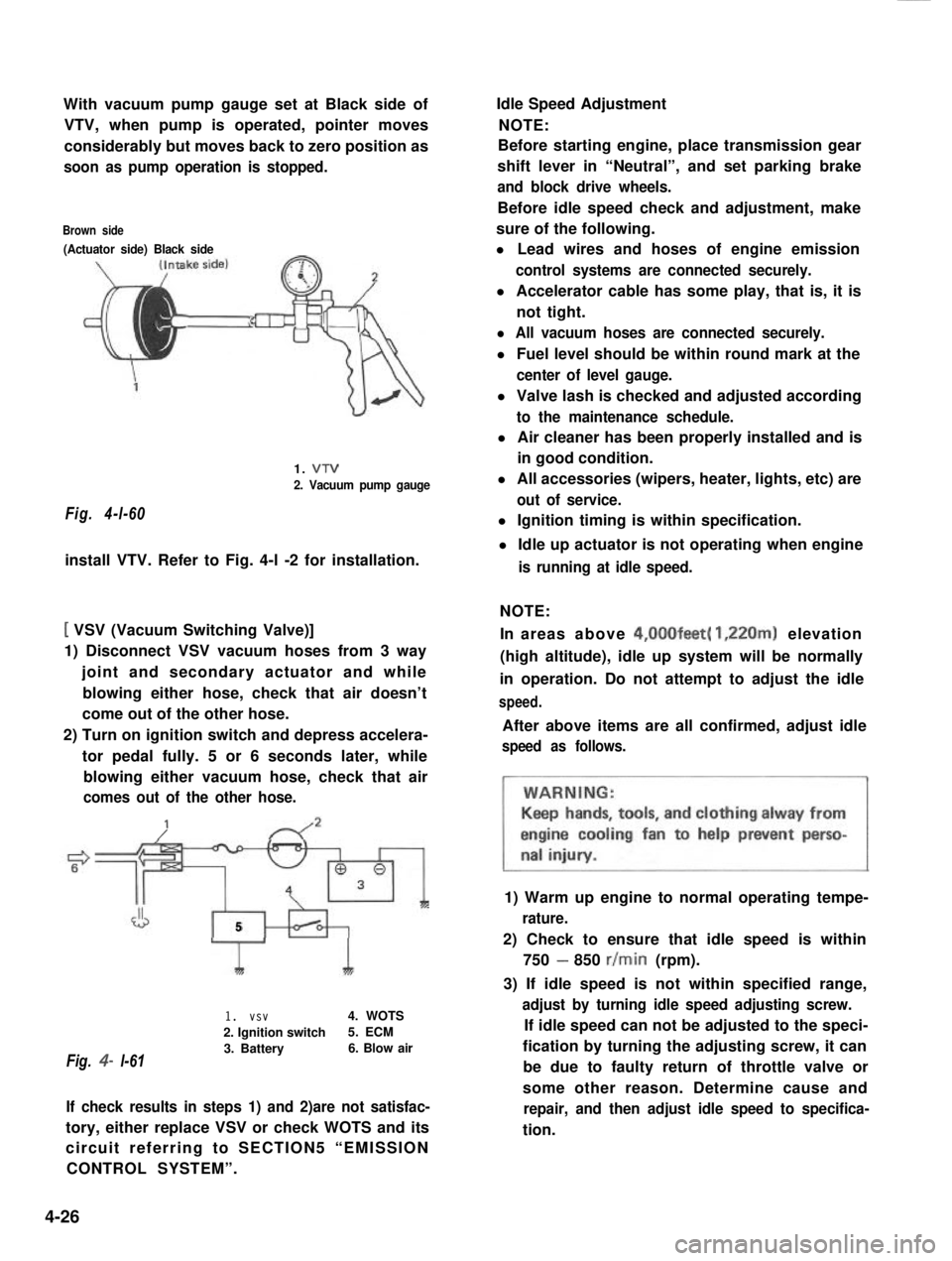
With vacuum pump gauge set at Black side of
VTV, when pump is operated, pointer moves
considerably but moves back to zero position as
soon as pump operation is stopped.
Brown side
(Actuator side) Black side
Fig. 4-l-60
1. VTV
2. Vacuum pump gauge
install VTV. Refer to Fig. 4-l -2 for installation.
[ VSV (Vacuum Switching Valve)]
1) Disconnect VSV vacuum hoses from 3 way
joint and secondary actuator and while
blowing either hose, check that air doesn’t
come out of the other hose.
2) Turn on ignition switch and depress accelera-
tor pedal fully. 5 or 6 seconds later, while
blowing either vacuum hose, check that air
comes out of the other hose.
J5
Fig. 4- l-61
1I
1. vsv4. WOTS
2. Ignition switch5. ECM
3. Battery6. Blow air
If check results in steps 1) and 2)are not satisfac-
tory, either replace VSV or check WOTS and its
circuit referring to SECTION5 “EMISSION
CONTROL SYSTEM”.
Idle Speed Adjustment
NOTE:
Before starting engine, place transmission gear
shift lever in “Neutral”, and set parking brake
and block drive wheels.
Before idle speed check and adjustment, make
sure of the following.
l Lead wires and hoses of engine emission
control systems are connected securely.
l Accelerator cable has some play, that is, it is
not tight.
l All vacuum hoses are connected securely.
l Fuel level should be within round mark at the
center of level gauge.
l Valve lash is checked and adjusted according
to the maintenance schedule.
l Air cleaner has been properly installed and is
in good condition.
l All accessories (wipers, heater, lights, etc) are
out of service.
l Ignition timing is within specification.
l Idle up actuator is not operating when engine
is running at idle speed.
NOTE:
In areas above 4,00Ofeet( 1,220m) elevation
(high altitude), idle up system will be normally
in operation. Do not attempt to adjust the idle
speed.
After above items are all confirmed, adjust idle
speed as follows.
1) Warm up engine to normal operating tempe-
rature.
2) Check to ensure that idle speed is within
750 - 850 r/min (rpm).
3) If idle speed is not within specified range,
adjust by turning idle speed adjusting screw.
If idle speed can not be adjusted to the speci-
fication by turning the adjusting screw, it can
be due to faulty return of throttle valve or
some other reason. Determine cause and
repair, and then adjust idle speed to specifica-
tion.
4-26
Page 146 of 962
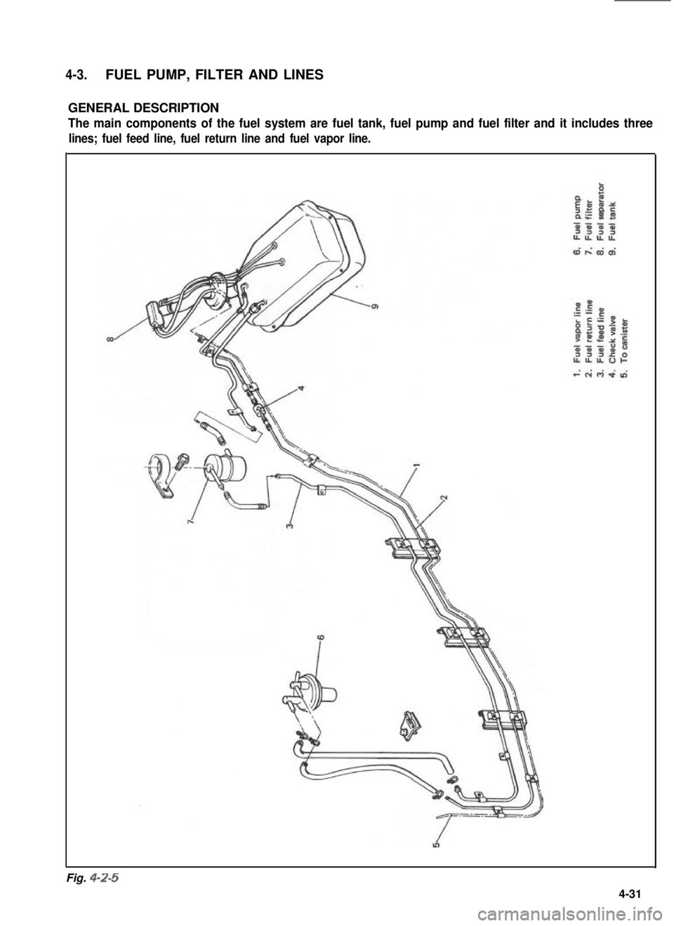
4-3.FUEL PUMP, FILTER AND LINES
GENERAL DESCRIPTION
The main components of the fuel system are fuel tank, fuel pump and fuel filter and it includes three
lines; fuel feed line, fuel return line and fuel vapor line.
Fig. 4-Z-5
4-31