1987 SUZUKI GRAND VITARA fuel pump
[x] Cancel search: fuel pumpPage 47 of 962
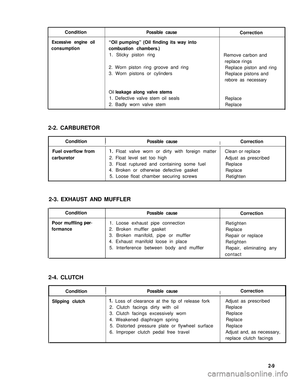
Condition
Excessive engine oil
consumption
Possible cause
“Oil pumping” (Oil finding its way into
combustion chambers.)
1. Sticky piston ring
2. Worn piston ring groove and ring
3. Worn pistons or cylinders
Correction
Remove carbon and
replace rings
Replace piston and ring
Replace pistons and
rebore as necessary
Oil leakage along valve stems
1. Defective valve stem oil sealsReplace
2. Badly worn valve stemReplace
2-2. CARBURETOR
ConditionPossible causeICorrection
Fuel overflow from
carburetor
1, Float valve worn or dirty with foreign matterClean or replace
2. Float level set too highAdjust as prescribed
3. Float ruptured and containing some fuelReplace
4. Broken or otherwise defective gasketReplace
5. Loose float chamber securing screwsRetighten
2-3. EXHAUST AND MUFFLER
Condition
Poor muffling per-
formance
Possible cause
1. Loose exhaust pipe connection
2. Broken muffler gasket
3. Broken manifold, pipe or muffler
4. Exhaust manifold loose in place
5. Interference between body and muffler
Correction
Retighten
Replace
Repair or replace
Retighten
Repair, eliminating any
contact
2-4. CLUTCH
ConditionPossible causeICorrection
Slipping clutch Loss of clearance at the tip of release fork
2. Clutch facings dirty with oil
3. Clutch facings excessively worn
4. Weakened diaphragm spring
5. Distorted pressure plate or flywheel surface
6. Improper clutch pedal free travel
Adjust as prescribed
Replace
Replace
Replace
Replace
Adjust and, as necessary,
replace clutch facings
2-9
1.
Page 62 of 962
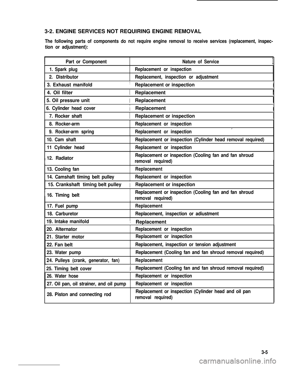
3-2. ENGINE SERVICES NOT REQUIRING ENGINE REMOVAL
The following parts of components do not require engine removal to receive services (replacement, inspec-
tion or adjustment):
Part or ComponentNature of Service1
1. Spark plug
2. Distributor
Replacement or inspection
Replacement, inspection or adjustment
1 3. Exhaust manifold1 Replacement or inspectionI
I 4. Oil filter1 ReplacementI
1 5. Oil pressure unit( Replacement
6. Cylinder head cover1 ReplacementI
I7. Rocker shaft1 Replacement or inspectionI
8. Rocker-arm
9. Rocker-arm spring
Replacement or inspection
Replacement or inspectionI
10. Cam shaft
11 Cylinder head
I12. Radiator
Replacement or inspection (Cylinder head removal required)
Replacement or inspection
Replacement or inspection (Cooling fan and fan shroud
removal required)I
13. Cooling fan
14. Camshaft timing belt pulley
Replacement
Replacement or inspection
I
15. Crankshaft timing belt pulley
16. Timing beltReplacement or inspection (Cooling fan and fan shroud
1 Replacement or inspection
removal required)
17. Fuel pump
18. Carburetor
Replacement
Replacement, inspection or adiustment
19. Intake manifold1 ReplacementI
20. Alternator
21. Starter motor
Replacement or inspection
22. Fan belt
23. Water pump
Replacement, inspection or tension adjustment
Replacement (Cooling fan and fan shroud removal required)
24.Pulleys (crank, generator, fan)Replacement
25. Timing belt cover)Replacement (Cooling fan and fan shroud removal required)
26. Water hose
27. Oil pan, oil strainer, and oil pump
Replacement or inspection
Replacement or inspection
28. Piston and connecting rodReplacement or inspection (Cylinder head and oil pan
removal required)
Replacement or inspection
3-5
Page 63 of 962
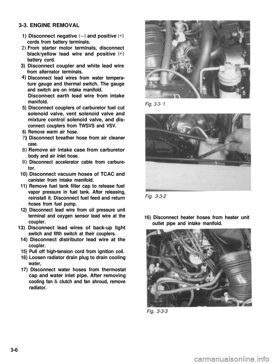
3-3. ENGINE REMOVAL
1) Disconnect negative (-) and positive (+)
cords from battery terminals.
‘)From starter motor terminals, disconnect
black/yellow lead wire and positive (+)
battery cord.
Disconnect coupler and white lead wire
from alternator terminals.
Disconnect lead wires from water tempera-
ture gauge and thermal switch. The gauge
and switch are on intake manifold.
Disconnect earth lead wire from intake
manifold.
5) Disconnect couplers of carburetor fuel cut
solenoid valve, vent solenoid valve and
mixture control solenoid valve, and dis-
connect couplers from TWSVS and VSV.
6) Remove warm air hose.
) Disconnect breather hose from air cleaner
case.
,) Remove air intake case from carburetor
body and air inlet hose.
1) Disconnect accelerator cable from carbure-
tor.
10) Disconnect vacuum hoses of TCAC and
canister from intake manifold.
11) Remove fuel tank filler cap to release fuel
vapor pressure in fuel tank. After releasing,
reinstall it. Disconnect fuel feed and return
hoses from fuel pump.
12) Disconnect lead wire from oil pressure unit
terminal and oxygen sensor lead wire at the
coupler.
13) Disconnect lead wires of back-up light
switch and fifth switch at their couplers.
14) Disconnect distributor lead wire at the
coupler.
15) Pull off high-tension cord from ignition coil.
16) Loosen radiator drain plug to drain cooling
water,
17) Disconnect water hoses from thermostat
cap and water inlet pipe. After removing
cooling fan & clutch and fan shroud, remove
radiator.
Fig. 3-3- 1
Fig. 3-3-2
16) Disconnect heater hoses from heater unit
outlet pipe and intake manifold.
Fig. 3-3-3
3)
4)
3-6
Page 66 of 962
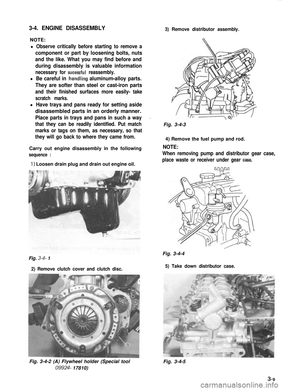
3-4. ENGINE DISASSEMBLY
NOTE:
3) Remove distributor assembly.
l Observe critically before starting to remove a
component or part by loosening bolts, nuts
and the like. What you may find before and
during disassembly is valuable information
necessary for sucessful reassembly.
l Be careful in .handling aluminum-alloy parts.
They are softer than steel or cast-iron parts
and their finished surfaces more easily- take
scratch marks.
l Have trays and pans ready for setting aside
disassembled parts in an orderly manner.
Place parts in trays and pans in such a way_.
that they can be readily identified. Put matchFig. 3-4-3
marks or tags on them, as necessary, so that
they will go back to where they came from.
4) Remove the fuel pump and rod.
Carry out engine disassembly in the following
NOTE:
sequence :When removing pump and distributor gear case,
1) Loosen drain plug and drain out engine oil.place waste or receiver under gear casa.
Fig. 3-4-4Fig. 3-4- 1
2) Remove clutch cover and clutch disc. 5) Take down distributor case.
Fig. 3-4-2 (A) Flywheel holder (Special tool09924-
17810) Fig. 3-4-5
Page 80 of 962
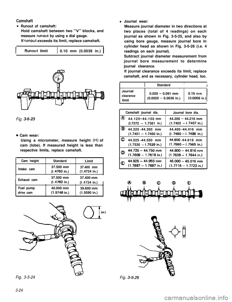
Camshaftl Journal wear:
l Runout of camshaft:
Hold camshaft between two “V” blocks, and
measure runout by using a dial gauge.
If runout exceeds its limit, replace camshaft.
Measure journal diameter in two directions at
two places (total of 4 readings) on each
journal as shown in Fig. 3-5-25, and also by
using bore gauge, measure journal bore in
cylinder head as shown in Fig. 3-5-26 (i.e. 4
readings on each journal).
Subtract journal diameter measurement from
journal bore measurement to determine
journal clearance.
If journal clearance exceeds its limit, replace
camshaft, and as necessary, cylinder head, too.
IRunout limit1 0.10 mm (0.0039 in.) 1
Fig. 3-5-23
0 Cam wear:
Using a micrometer, measure height (H) of
cam (lobe). If measured height is less than
respective limits, replace camshaft.
Cam heightStandardLimit
Intake cam37.500 mm37.400 mm
(I .4763 in.)(1.4724 in.),
IExhaust cam37.500 mm37.400 mm
(I .4763 in.)(I .4724 in.)IrFuel pump40.000 mm39.600 mm
drive cam(I .5748 in.)(1.5590 in.)
Fig. 3-5-24
3-24
IIStandard1I
Journal
clearance
limit
0.050 - 0.091 mm
(0.0020 - 0.0036 in.)
Camshaft journal dia.Journal bore dia.
@44.125 44.150-mm44.200 - 44.216 mm
(I.7372 - 1.7381in.)(1.7402 - I .7407 in.)
@44.325 44.350 mm- 44.400 44.416 mm
(1.7451 - 1.7460 in.)(I .7480 - I .7486 in.)
044.525 44.550 mm-44~600 44.616 mm-
(1.7530 - I .7539 in.)(I .7560 - I .7565 in.)
Fig. 3-5-25
Page 108 of 962
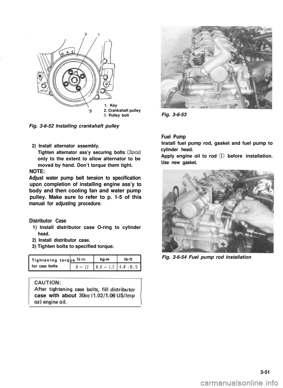
-1. Key
‘32. Crankshaft pulley3. Pulley bolt
Fig. 3-6-52 Installing crankshaft pulley
2) Install alternator assembly.
Tighten alternator ass’y securing bolts (3pcs)
only to the extent to allow alternator to be
moved by hand. Don’t torque them tight.
NOTE:
Adjust water pump belt tension to specification
upon completion of installing engine ass’y to
body and then cooling fan and water pump
pulley. Make sure to refer to p. 1-5 of this
manual for adjusting procedure.
Distributor Case
1) Install distributor case O-ring to cylinder
head.
2) Install distributor case.
3) Tighten bolts to specified torque.
Tightening torque N.mkg-mlb-ft
forcasebolts8-120.8-1.26.0-8.5
Fig. 3-6-53
Fuel Pump
Install fuel pump rod, gasket and fuel pump to
cylinder head.
Apply engine oil to rod @ before installation.
Use new gasket.
Fig. 3-6-54 Fuel pump rod installation
case with about 3Occ (1.02/1.05 US/Imp
3-51
Page 115 of 962
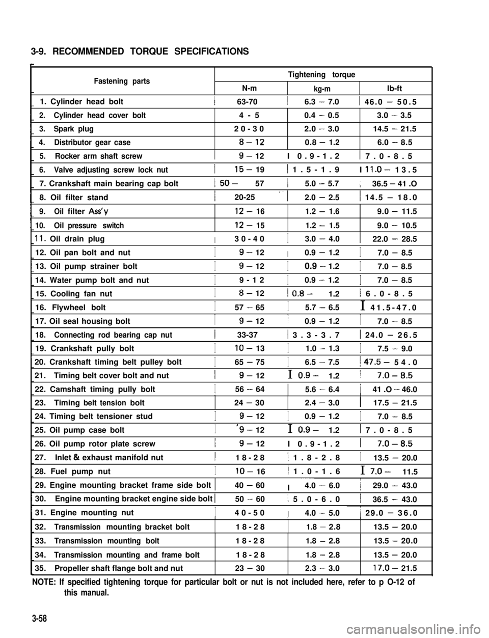
3-9. RECOMMENDED TORQUE SPECIFICATIONS
Fastening partsN-m
Tightening torque
kg-mlb-ft
1. Cylinder head bolt1 63-7016.3 - 7.01 46.0 - 50.5
2.Cylinder head cover bolt4-50.4-0.53.0-3.5
3.Spark plug20-302.0-3.014.5-21.5
4.Distributor gear case8-120.8-1.26.0-8.5
5.Rocker arm shaft screwI9- 12I 0.9-1.21 7.0-8.5
6.Valve adjusting screw lock nut
7. Crankshaft main bearing cap bolt
8. Oil filter stand
I15- 191 1.5-1.9I ll.O- 13.5
1 50- 5715.0 - 5.7136.5 - 41 .O
I20-25 -. 12.0 - 2.51 14.5 - 18.0
9.Oilfilter Ass’y12-161.2-1.69.0-11.5
10.Oilpressure switch12-151.2-1.59.0-10.5
11. Oil drain plugI30-40I3.0 - 4.0122.0 - 28.5
12. Oil pan bolt and nutI9- 12I0.9 - 1.2I7.0 - 8.5
13. Oil pump strainer bolt
14. Water pump bolt and nut
I9- 12I0.9 - 1.2I7.0 - 8.5
I9-12I0.9 - 1.2I7.0 - 8.5
15. Cooling fan nutI8- 121 0.8- 1.21 6.0-8.5
16. Flywheel boltI57 - 65I5.7 - 6.5I 41.5-47.0
17. Oil seal housing boltI9- 12I0.9 - 1.2I7.0 - 8.5
18.Connecting rod bearing cap nut1 33-37( 3.3-3.71 24.0 - 26.5
19. Crankshaft pully boltIlo- 13I1.0 - 1.3I7.5 - 9.0
20. Crankshaft timing belt pulley bolt
21.Timing belt cover bolt and nut
I65 - 75I6.5 - 7.51 47.5- 54.0
I9- 12I 0.9- 1.21 7-O-8.5
22. Camshaft timing pully boltI56 - 6415.6 - 6.4141 .O - 46.0III
23.Timingbelttensionbolt24-302.4-3.0117.5-21.5
24. Timing belt tensioner studI9- 12I0.9 - 1.2I7.0 - 8.5
25. Oil pump case boltI‘9- 12I 0.9- 1.21 7.0-8.5
26. Oil pump rotor plate screwI9- 12I 0.9-1.21 7-O-8.5
27.Inlet & exhaust manifold nutI18-281 1.8-2.8I13.5 - 20.0
28. Fuel pump nutIlo- 161 1.0-1.6I 7.0- 11.5
29. Engine mounting bracket frame side bolt 140 - 60I ~~~4.0 - 6.0129.0 - 43.0
30.Engine mounting bracket engine side bolt I50 - 601 5.0-6.0136.5 - 43.0
31. Engine mounting nutI40-50I4.0 - 5.01 29.0 - 36.0I1I
32.Transmissionmountingbracketbolt18-281.8-2.8113.5-20.0
33.Transmission mounting bolt18-281.8-2.813.5 -20.0
34.Transmission mounting and framebolt18-281.8-2.813.5 -20.0
35.Propeller shaft flange bolt and nut23 - 302.3-3.017.0-21.5
NOTE: If specified tightening torque for particular bolt or nut is not included here, refer to p O-12 of
this manual.
3-58
Page 116 of 962
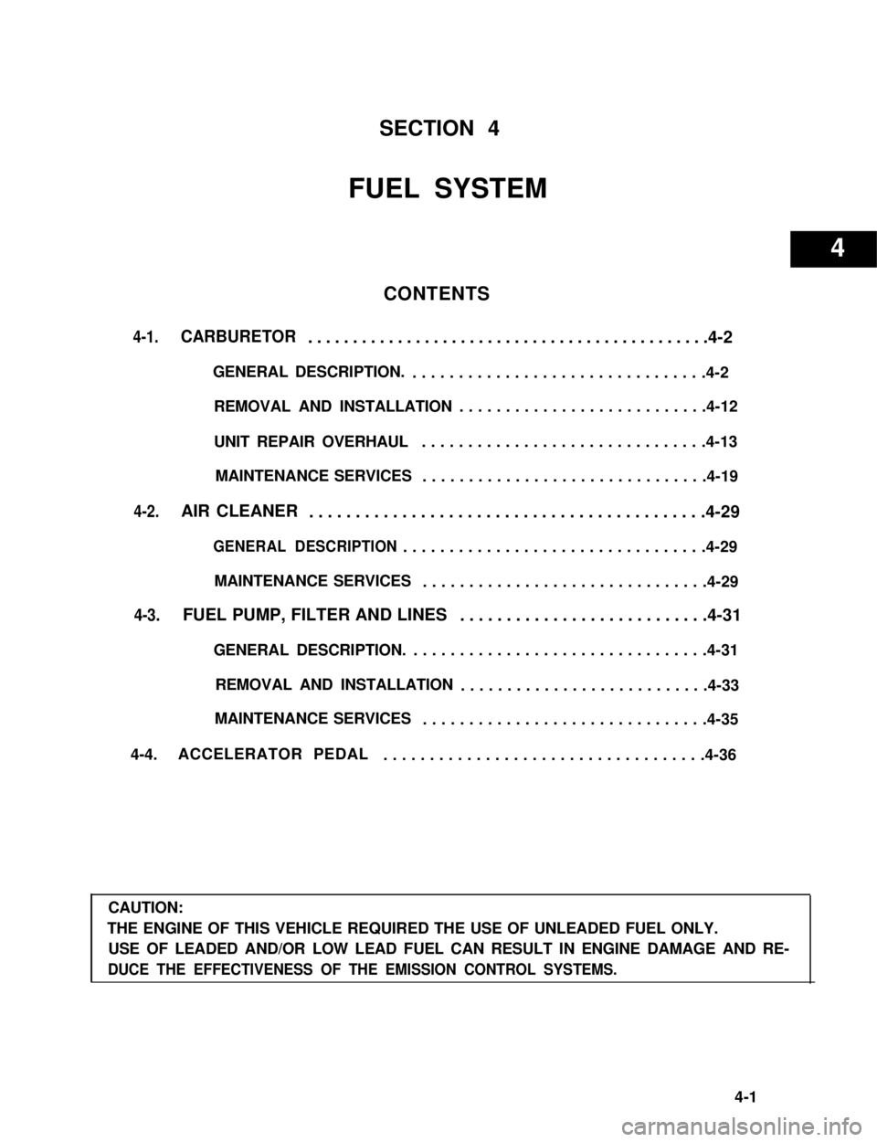
SECTION 4
FUEL SYSTEM
CONTENTS
4-1.CARBURETOR.............................................4-2
GENERAL DESCRIPTION.................................4-2
REMOVAL AND INSTALLATION...........................4-12
UNIT REPAIR OVERHAUL...............................4-13
MAINTENANCE SERVICES...............................4-19
4-2.AIR CLEANER...........................................4-29
GENERAL DESCRIPTION.................................4-29
MAINTENANCE SERVICES...............................4-29
4-3.FUEL PUMP, FILTER AND LINES...........................4-31
GENERAL DESCRIPTION.................................4-31
REMOVAL AND INSTALLATION...........................4-33
MAINTENANCE SERVICES...............................4-35
4-4.ACCELERATOR PEDAL...................................4-36
CAUTION:
THE ENGINE OF THIS VEHICLE REQUIRED THE USE OF UNLEADED FUEL ONLY.
USE OF LEADED AND/OR LOW LEAD FUEL CAN RESULT IN ENGINE DAMAGE AND RE-
DUCE THE EFFECTIVENESS OF THE EMISSION CONTROL SYSTEMS.
4-1
4