1987 SUZUKI GRAND VITARA air filter
[x] Cancel search: air filterPage 45 of 962
9
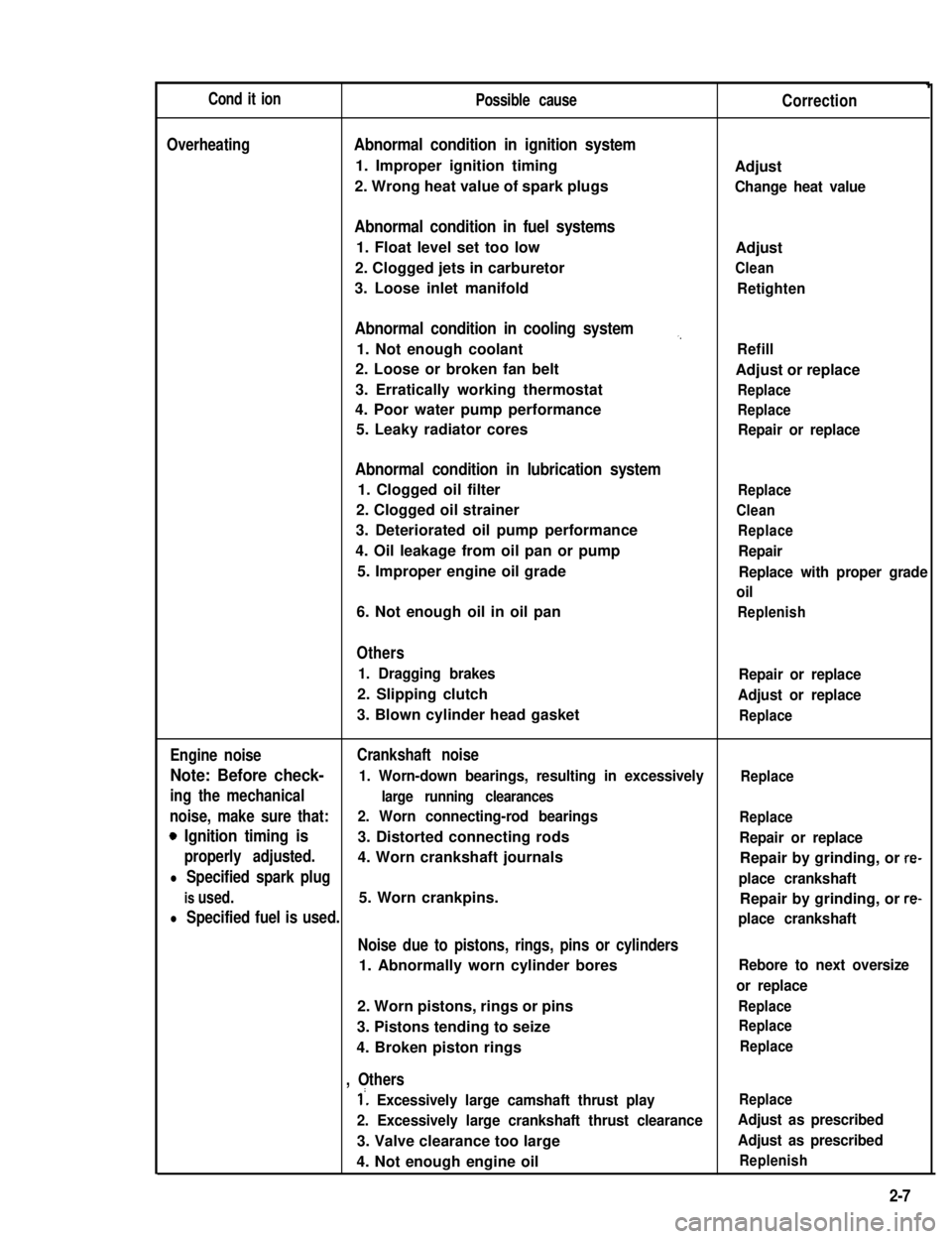
Cond it ionPossible causeCorrection
OverheatingAbnormal condition in ignition system
1. Improper ignition timingAdjust
2. Wrong heat value of spark plugsChange heat value
Abnormal condition in fuel systems
1. Float level set too lowAdjust
2. Clogged jets in carburetorClean
3. Loose inlet manifoldRetighten
Abnormal condition in cooling system,,
1. Not enough coolantRefill
2. Loose or broken fan beltAdjust or replace
3. Erratically working thermostatReplace
4. Poor water pump performanceReplace
5. Leaky radiator coresRepair or replace
Abnormal condition in lubrication system
1. Clogged oil filterReplace
2. Clogged oil strainerClean
3. Deteriorated oil pump performanceReplace
4. Oil leakage from oil pan or pumpRepair
5. Improper engine oil gradeReplace with proper grade
oil
6. Not enough oil in oil panReplenish
Others
1. Dragging brakesRepair or replace
2. Slipping clutchAdjust or replace
3. Blown cylinder head gasketReplace
Engine noiseCrankshaft noise
Note: Before check- 1. Worn-down bearings, resulting in excessivelyReplace
ing the mechanicallarge running clearances
noise, make sure that:2. Worn connecting-rod bearingsReplace
0 Ignition timing is3. Distorted connecting rodsRepair or replace
properly adjusted.4. Worn crankshaft journalsRepair by grinding, or re-
l Specified spark plugplace crankshaft
is used.5. Worn crankpins.Repair by grinding, or re-
l Specified fuel is used.place crankshaft
Noise due to pistons, rings, pins or cylinders
1. Abnormally worn cylinder boresRebore to next oversize
or replace
2. Worn pistons, rings or pinsReplace
3. Pistons tending to seizeReplace
4. Broken piston ringsReplace
, Others
1’. Excessively large camshaft thrust playReplace
2. Excessively large crankshaft thrust clearanceAdjust as prescribed
3. Valve clearance too largeAdjust as prescribed
4. Not enough engine oilReplenish
2-7
Page 46 of 962

ConditionPossible causeCorrection
High fuel consumptionAbnormal condition ignition system
1. Improper ignition timingAdjust
2. Leak or loose connection of high tension cordRepair or replace
3. Defective spark plug (improper gap, heavyClean, adjust or replace
deposits, and burned electrodes, etc..)
4. Cracked distributor cap or rotorReplace
5. Malfunctioning mechanical and vacuumCheck and repair or
advancers in distributorreplace
Abnormal condition in fuel system
1. Improper float levelAdjust
2. Fuel leakage from tank, pipe or carburetorRepair or replace
3. Malfunctioning carburetor choke systemRepair or replace
4. Dirty or clogged carburetor jetsClean
5. Clogged air cleaner elementClean or replace
6. Malfunctioning thermostatically controlledCheck and repair or
air cleanerreplace
Abnormal condition in engine
1. Low compressionPreviously outlined
2. Poor valve seatingRepair or replace
3. Improper valve clearanceAdjust
Emission control
1. Air leaks at exhaust manifoldTighten manifold bolts
and nuts.
Replace gasket.
2. Oxygen sensor out of orderReplace.
3. Water temperature switch out of orderReplace.
4. Malfunctioning throttle position switchReplace
5. Malfunctioning MCS (mixture controlReplace
solenoid) valve in carburetor
6. Malfunctioning EGR valveReplace
Others
1. Dragging brakesRepair or replace
2. Slipping clutchAdjust or replace
3. Improper tire pressureAdjust
Excessive engine oilOil leakage
consumption1. Loose oil drain plugTighten
2. Loose oil pan securing boltsTighten
3. Deteriorated or broken oil pan sealantReplace sealant
4. Leaky oil sealsReplace
5. Blown cylinder head gasketReplace
6. Improper tightening of oil filterTighten
7. Loose oil pressure switchTighten
2-8
Page 116 of 962

SECTION 4
FUEL SYSTEM
CONTENTS
4-1.CARBURETOR.............................................4-2
GENERAL DESCRIPTION.................................4-2
REMOVAL AND INSTALLATION...........................4-12
UNIT REPAIR OVERHAUL...............................4-13
MAINTENANCE SERVICES...............................4-19
4-2.AIR CLEANER...........................................4-29
GENERAL DESCRIPTION.................................4-29
MAINTENANCE SERVICES...............................4-29
4-3.FUEL PUMP, FILTER AND LINES...........................4-31
GENERAL DESCRIPTION.................................4-31
REMOVAL AND INSTALLATION...........................4-33
MAINTENANCE SERVICES...............................4-35
4-4.ACCELERATOR PEDAL...................................4-36
CAUTION:
THE ENGINE OF THIS VEHICLE REQUIRED THE USE OF UNLEADED FUEL ONLY.
USE OF LEADED AND/OR LOW LEAD FUEL CAN RESULT IN ENGINE DAMAGE AND RE-
DUCE THE EFFECTIVENESS OF THE EMISSION CONTROL SYSTEMS.
4-1
4
Page 117 of 962
4-1. CARBURETOR
GENERAL DESCRIPTION
General
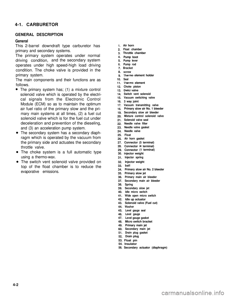
This 2-barrel downdraft type carburetor has
primary and secondary systems.
The primary system operates under normal
driving condition,and the secondary system
operates under high speed-high load driving
condition. The choke valve is provided in the
primary system.
The main components and their functions are as
follows.
The primary system has; (1) a mixture control
solenoid valve which is operated by the electri-
cal signals from the Electronic Control
Module (ECM) so as to maintain the optimum
air fuel ratio of the primary slow and the pri-
mary main systems at all times, (2) a fuel cut
solenoid valve which is for the fuel cut under
deceleration and prevention of the dieseling,
and (3) an acceleration pump system.
The secondary system has a secondary diaph-
ragm which is operated by the vacuum from
the primary side and actuates the secondary
throttle valve.
The choke system is a full automatic type
using a thermo-wax.
The switch vent solenoid valve provided on
top of the float chamber is to reduce the
evaporative emissions.
1.Air horn
2.Float chamber
3.Throttle chamber
4.Pump boot5.Pump lever
6.Pump rod
7.Bracket
8.screw
9.Therm0 element holder
10.Seal
11.Therm0 element
12.Choke piston
13.Delay valve
14.Switch vent solenoid
15.Vacuum switching valve
16.3 way joint
17.Vacuum transmitting valve
16.Primary slow air No. 1 bleeder
19.Secondary slow air bleeder
20.Mixture control solenoid valve
21.Solenoid valve seal
22.Needle valve filter
23.Needle valve gasket
24.Needle valve
25.Float
26.Air horn gasket
27.Connector (5 terminal)
28.Connector (4 terminal)
29.Connector (1 terminal)
30. injector weight
31.Injector spring
32.Injector weight
33.
34.Primary slow air No. 2 bleeder
35.Primary slow jet
36.Primary main air bleeder
37.Secondary main air bleeder
38.Spring
39.Secondary slow jet
40.Idle micro switch
41.Wide open micro switch
42.Idle up actuator43.Solenoid valve (Fuel cut)
44.Washer
45.Level gauge seal
46.Level gauge
47.Level gauge gasket
48.Micro switch bracket
49.Primary main jet
60.Secondary main jet
51.Drain plug gasket
52,Drain plug
53. Float pin54. Insulator56. Secondary actuator (diaphragm)
4-2
ball
Page 129 of 962
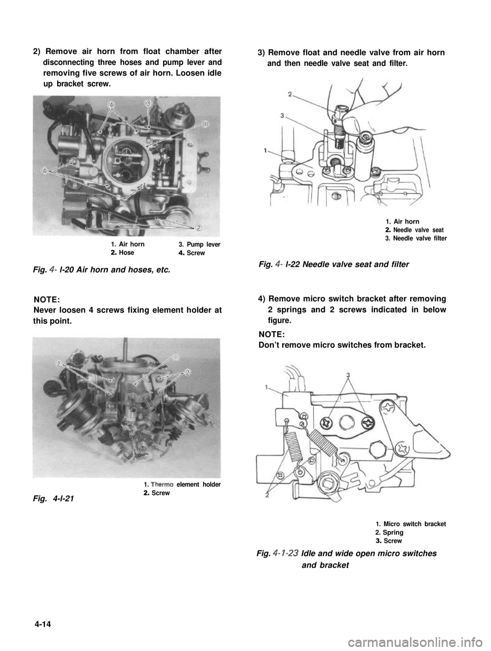
2) Remove air horn from float chamber after
disconnecting three hoses and pump lever and
removing five screws of air horn. Loosen idle
up bracket screw.
3) Remove float and needle valve from air horn
and then needle valve seat and filter.
1. Air horn
2. Needle valve seat
3. Needle valve filter1. Air horn3. Pump lever2. Hose4. Screw
Fig. 4- l-22 Needle valve seat and filterFig. 4- l-20 Air horn and hoses, etc.
NOTE:
Never loosen 4 screws fixing element holder at
this point.
4) Remove micro switch bracket after removing
2 springs and 2 screws indicated in below
figure.
NOTE:
Don’t remove micro switches from bracket.
1. Therm0 element holder
2. ScrewFig. 4-l-21
1. Micro switch bracket
2. Spring
3. Screw
Fig. 4- l-23 Idle and wide open micro switches
and bracket
4-14
Page 130 of 962
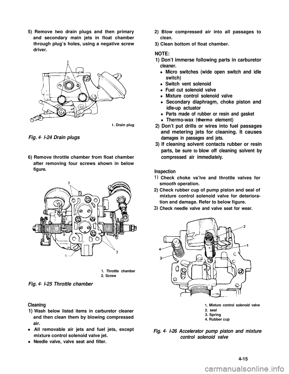
5) Remove two drain plugs and then primary
and secondary main jets in float chamber
through plug’s holes, using a negative screw
driver.
1. Drain plug
Fig. 4- l-24 Drain plugs
6) Remove throttle chamber from float chamber
after removing four screws shown in below
figure.
1. Throttle chamber
2. Screw
Fig. 4- l-25 Throttle chamber
Cleaning
1) Wash below listed items in carburetor cleaner
and then clean them by blowing compressed
air.
l All removable air jets and fuel jets, except
mixture control solenoid valve jet.
l Needle valve, valve seat and filter.
2) Blow compressed air into all passages to
clean.
3) Clean bottom of float chamber.
NOTE:
1) Don’t immerse following parts in carburetor
cleaner.
l Micro switches (wide open switch and idle
switch)
l Switch vent solenoid
l Fuel cut solenoid valve
l Mixture control solenoid valve
l Secondary diaphragm, choke piston and
idle-up actuator
l Parts made of rubber or resin and gasket
l Thermo-wax (therm0 element)
2) Don’t put drills or wires into fuel passages
and metering jets for cleaning. It causes
damages in passages and jets.
3) If cleaning solvent contacts rubber or resin
parts, be sure to blow off cleaning solvent by
compressed air immediately.
Inspection
1) Check choke va’lve and throttle valves for
smooth operation.
2) Check rubber cup of pump piston and seal of
mixture control solenoid valve for deteriora-
tion and damage. Refer to below figure.
3) Check needle valve and valve seat for wear.
1. Mixture control solenoid valve
2. seal3. Spring4. Rubber cup
Fig. 4- l-26 Accelerator pump piston and mixture
control solenoid valve
4-15
Page 133 of 962
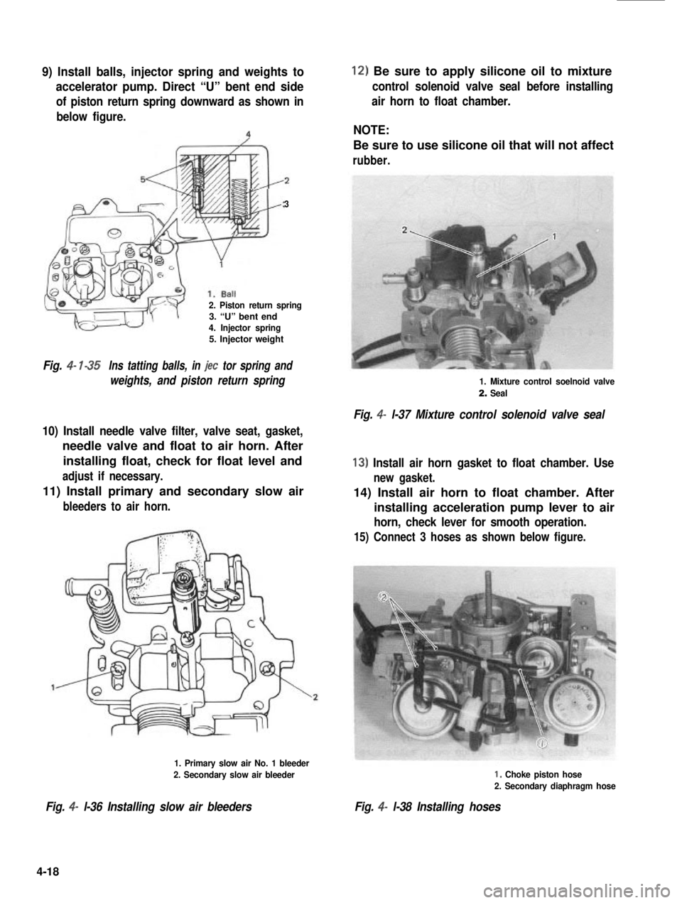
9) Install balls, injector spring and weights to
accelerator pump. Direct “U” bent end side
of piston return spring downward as shown in
below figure.
3
2. Piston return spring3. “U” bent end4. Injector spring5. Injector weight
Fig. 4- l-35Ins tatting balls, in jet tor spring and
weights, and piston return spring
10) Install needle valve filter, valve seat, gasket,
needle valve and float to air horn. After
installing float, check for float level and
adjust if necessary.
11) Install primary and secondary slow air
bleeders to air horn.
1. Primary slow air No. 1 bleeder
2. Secondary slow air bleeder
Fig. 4- l-36 Installing slow air bleeders
12) Be sure to apply silicone oil to mixture
control solenoid valve seal before installing
air horn to float chamber.
NOTE:
Be sure to use silicone oil that will not affect
rubber.
1. Mixture control soelnoid valve
2. Seal
Fig. 4- l-37 Mixture control solenoid valve seal
13) Install air horn gasket to float chamber. Use
new gasket.
14) Install air horn to float chamber. After
installing acceleration pump lever to air
horn, check lever for smooth operation.
15) Connect 3 hoses as shown below figure.
I, Choke piston hose
2. Secondary diaphragm hose
Fig. 4- l-38 Installing hoses
4-18
Page 144 of 962
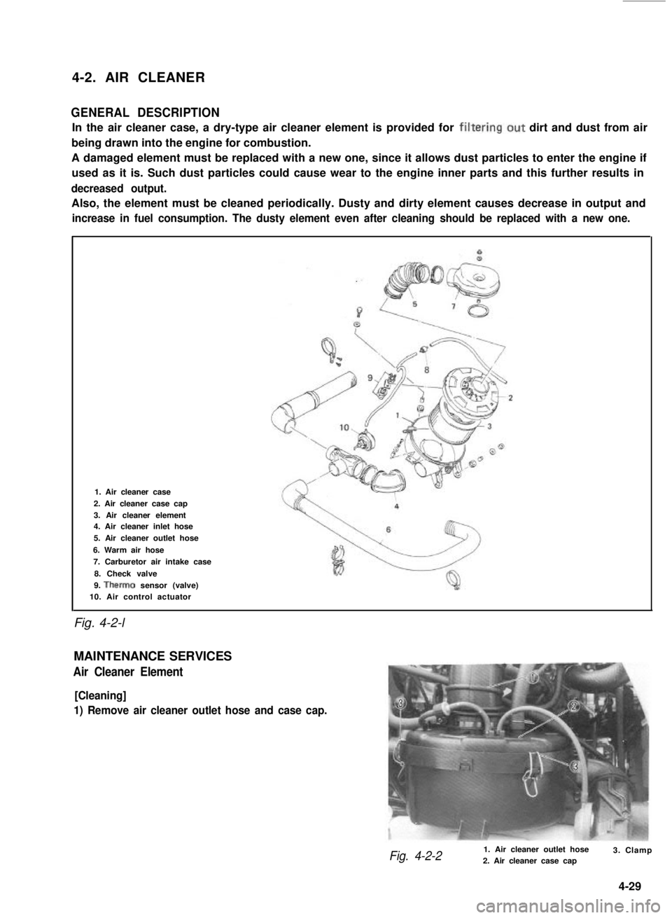
4-2. AIR CLEANER
GENERAL DESCRIPTION
In the air cleaner case, a dry-type air cleaner element is provided for filtering.out dirt and dust from air
being drawn into the engine for combustion.
A damaged element must be replaced with a new one, since it allows dust particles to enter the engine if
used as it is. Such dust particles could cause wear to the engine inner parts and this further results in
decreased output.
Also, the element must be cleaned periodically. Dusty and dirty element causes decrease in output and
increase in fuel consumption. The dusty element even after cleaning should be replaced with a new one.
Fig. 4-2-l
1. Air cleaner case
2. Air cleaner case cap
3. Air cleaner element4. Air cleaner inlet hose
5. Air cleaner outlet hose
6. Warm air hose
7. Carburetor air intake case
8. Check valve
9. Therm0 sensor (valve)10. Air control actuator
MAINTENANCE SERVICES
Air Cleaner Element
[Cleaning]
1) Remove air cleaner outlet hose and case cap.
Fig. 4-2-21. Air cleaner outlet hose2. Air cleaner case cap3. Clamp
4-29