Page 421 of 962

2,
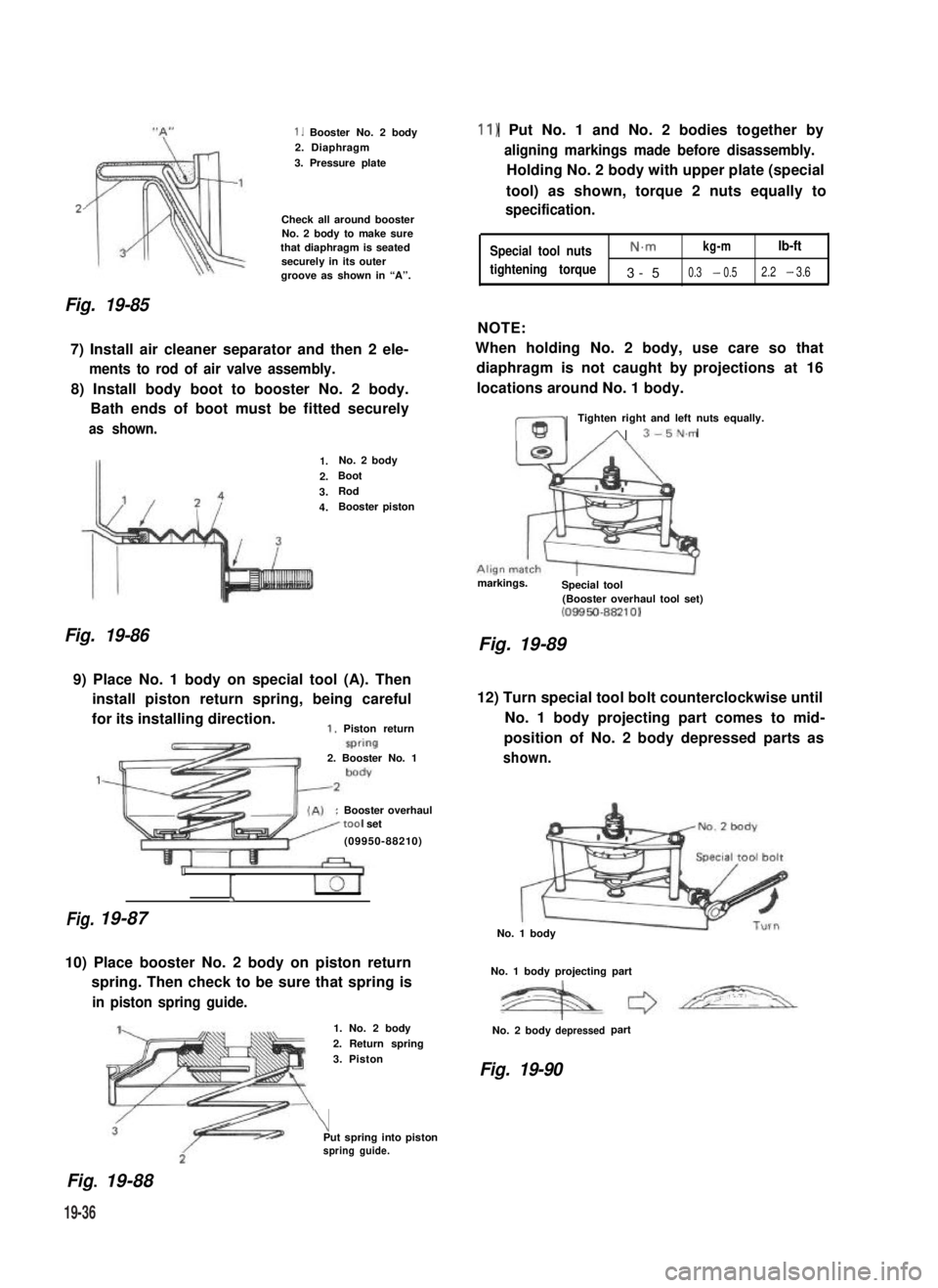
Fig. 19-85
1. Booster No. 2 body2. Diaphragm
3. Pressure plate
Check all around boosterNo. 2 body to make surethat diaphragm is seatedsecurely in its outergroove as shown in “A”.
7) Install air cleaner separator and then 2 ele-
ments to rod of air valve assembly.
8) Install body boot to booster No. 2 body.
Bath ends of boot must be fitted securely
as shown.
Fig. 19-86
1.No. 2 body
2.Boot
3.Rod
4.Booster piston
9) Place No. 1 body on special tool (A). Then
install piston return spring, being careful
for its installing direction.1. Piston return
Fig.
2. Booster No. 1
:Booster overhaultool set
(09950-88210)
1
I
19-87
10) Place booster No. 2 body on piston return
spring. Then check to be sure that spring is
in piston spring guide.
Fig.. 19-88
1. No. 2 body
2. Return spring
3. Piston
\Put spring into pistonspring guide.
11) Put No. 1 and No. 2 bodies together by
aligning markings made before disassembly.
Holding No. 2 body with upper plate (special
tool) as shown, torque 2 nuts equally to
specification.
Special tool nutsN.mkg-mlb-ft
tightening torque3-50.3 - 0.52.2 - 3.6
NOTE:
When holding No. 2 body, use care so that
diaphragm is not caught by projections at 16
locations around No. 1 body.
ml
Tighten right and left nuts equally.
A 3-5N.m
markings.Special tool(Booster overhaul tool set)(08850-88210)
Fig. 19-89
12) Turn special tool bolt counterclockwise until
No. 1 body projecting part comes to mid-
position of No. 2 body depressed parts as
shown.
No. 1 body
No. 1 body projecting part
No. 2 bodydepressedpart
Fig. 19-90
19-36
Page 424 of 962

19-7. BRAKE PIPES AND HOSES
REMOVAL AND INSTALLATION
1) Take out fluid with a cyringe or such.
2) Clean dirt and foreign material from both
hose end or pipe end fittings. Remove brake
hose or pipe.
3) Reverse removal procedure for brake hose
or pipe installation.When installing hose,
make sure that it has no twists or kinks.
Inspect to see that hose doesn’t make contact
with any part of suspension. Check in extreme
right and extreme left turn conditions. If
hose makes .any contact, remove and correct.
Fill and maintain brake fluid level in reser-
voir. Bleed brake system.
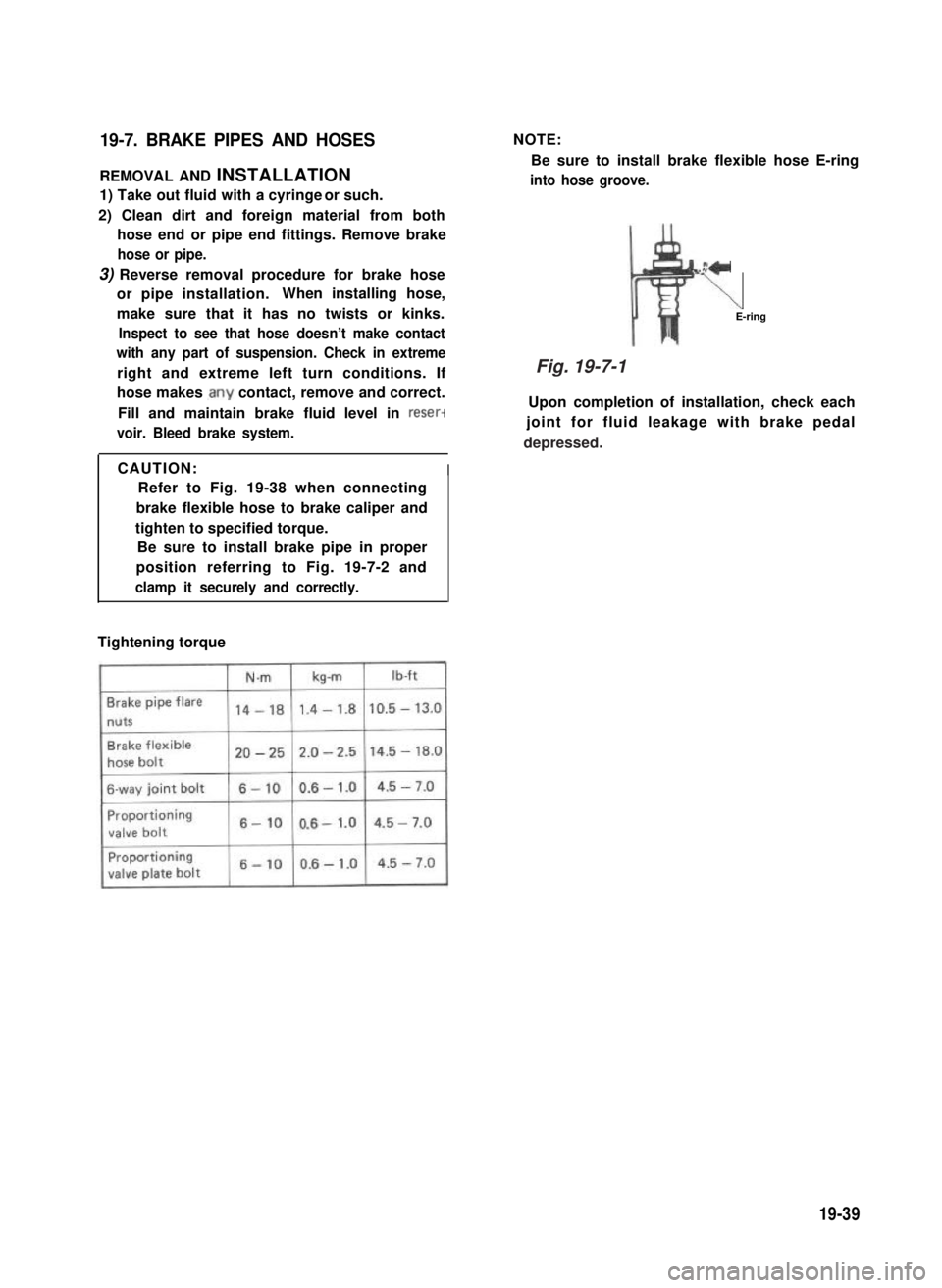
NOTE:
Be sure to install brake flexible hose E-ring
into hose groove.
z+
\E-ring
Upon completion of installation, check each
joint for fluid leakage with brake pedal
CAUTION:I
Refer to Fig. 19-38 when connecting
brake flexible hose to brake caliper and
tighten to specified torque.
Be sure to install brake pipe in proper
position referring to Fig. 19-7-2 and
clamp it securely and correctly.
Tightening torque
19-39
Fig. 19-7-1
depressed.
Page 425 of 962

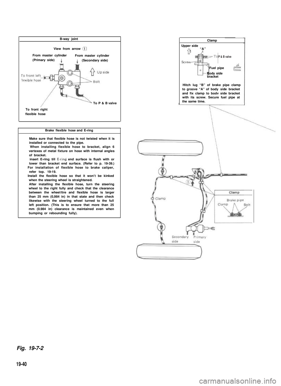
B-way joint
View from arrow @
From master cylinderFrom master cylinder(Primary side)4(Secondary side)
To P & B valve
To front rightflexible hose
Brake flexible hose and E-ring
Make sure that flexible hose is not twisted when it isinstalled or connected to the pipe.When installing flexible hose to bracket, align 6vertexes of metal fixture on hose with internal anglesof bracket.insert E-ring till Ewing end surface is flush with orlower than bracket end surface. (Refer to p. 19-39.) For installation of flexible hose to brake caliper,refer top. 19-19. Install the flexible hose so that it won’t be kinkedwhen the steering wheel is straightened.After installing the flexible hose, turn the steeringwheel to the right fully and check that the clearancebetween the wheel/tire and flexible hose is largerthan 25 mm (0,984 in) in that state and then checklikewise with the steering wheel turned to the fullleft position. (This is to ensure that more than 25mm (0.984 in) clearance is maintained even whenbumping or rebounding fully).
Clamp
Upper sideA“A”71’/
sre~~To
Tr
Fuel pipe0Body sidebracket
Hitch lug “B” of brake pipe clampto groove “A” of body side bracketand fix clamp to bodv side bracketwith its screw. Secure fuel pipe atthe same time.
Fig. 19-7-2
19-40
P & B valve
Page 426 of 962
Clamp
Up side
Brake pipe
Brake pipes (Right side)
Install brake pipe to
Up sidewheel cylinder pro-perly using care forits installing posi-tion.
cylinder
Blake backing Plato (Right & Left)
When installing backing plateontoaxle housing, applySEALING COMPOUND 366E(99000-31090) to mating sur-faces of both parts.
Brake backing plate
compound
hose groove securelyand clamp hose.
Air bleeder
(To flexible hose)
wheel cylinder pro-perly using care foritsinstallrng posi-tion.
Rear axle
IBrake pipe
1Rear axle
P & B valve
View from arrow @
Up side
From 6-way joint
Plug
To rear flexible hose
19-41
Page 437 of 962
REMOVAL
Door Window Glass
1) Remove door window regulator handle.
Fig. 20-1-2
2) Remove inside handle case.
Fig. 20-1-3
3) Remove inside pull handle.
4) Loosen two screws securing the stopper
band, and take off the band.
5) Remove door trim board.
Fig. 20-1-5
6) Remove the door water proof film.
Fig. 20-1-6
7) Remove the glass inside and outside scrape.
Fig. 20-1-4 Fig. 20-1-7
20-3
Page 438 of 962
8) Remove 2 screws securing the door window
regulator roller holder (lower side).
Fig. 20-1-10
Fig. 20-1-8
9) Take out the glass.
Fig. 20-1-9
10) Detach glass from bottom channel.
Door Window Regulator
After carrying out door glass removal steps 1)
through 6) and 8), move on to the following
steps to take off the door window regulator.
1) Remove 2 screws securing the door window
regulator roller holder (upper side).
NOTE:
Make sure to support the glass to keep it from
falling while removing the screws.
2) Remove 4 screws securing the window regula-
tor.
Fig. 20-1-11
3) Remove the window regulator.
Fig. 20-1-12
20-4
Page 441 of 962
![SUZUKI GRAND VITARA 1987 Service Repair Manual [Door lock inside handle]
Fit the inside handle, adjusting the clearance
between inside open lever @I and outside open
lever @I of the door lock to 0 - 2 mm (0 -
0,079 in) by moving the inside handle SUZUKI GRAND VITARA 1987 Service Repair Manual [Door lock inside handle]
Fit the inside handle, adjusting the clearance
between inside open lever @I and outside open
lever @I of the door lock to 0 - 2 mm (0 -
0,079 in) by moving the inside handle](/manual-img/20/57437/w960_57437-440.png)
[Door lock inside handle]
Fit the inside handle, adjusting the clearance
between inside open lever @I and outside open
lever @I of the door lock to 0 - 2 mm (0 -
0,079 in) by moving the inside handle remote
control rod @ in the arrow direction given in
below figure.
After installation, give it a trial and check if its
play felt then is appropriate.
8. Inside open lever
9. Outside open lever
10. Control rod
11. Door lock striker“B” :0 - 2 mm (0 - 0.079 in.)
Fig. 20-1-21
[Door lock rod pin]
Fix the lock rod with rod pin securely as illust-
rated below.
Rod pin
Fig. 20-1-22
[Door lock striker]
Increase or decrease striker spacers fitted in “A”
position behind the striker to adjust dimensions
to below values as shown in below figure.
After adjustment, check the difference in level
between the door and
there is difference by
striker to right or left.
body and adjust when
moving the door lock
Clearance3.0 mm
(0.12 in.)Spacer fitting position “A”r
Striker
Door lock base\JIA4Yl
y <1 Door inner panelDimension
H 12.7-14.7mm(0.499 - 0.579 in.)
Fig. 20-1-23
Move the striker base up and down so that
striker shaft aligns with the center of the groove
of the door lock (the clearance between the shaft
of door lock striker and lock base is 1.0 mm
(0.04 in.)) in the vertical direction.
CAUTION:
l The striker should be placed vertically.
l Do not adjust the door lock.
Door lock cam
Fig. 20-1-24
20-7
Page 466 of 962
21-15. WIRING HARNESS ROUTING
When reinstalling wire harness, be careful for the following.
l When doing wiring harness related work, make always sure to disconnect battery negative cable from
battery.
l Clamp wire harness securely at prescribed positions.
l Try to route wire harness so as to avoid contact with other parts as much as possible. Use special care
not to let it contact sharp edges of body or other parts.
0 Connect connectors securely.
Engine Room Wiring
1.Wire harness No. 2
2.Battery3. To starter, alternator, head light, small light, horn and etc.
4. To license light, stop/tail light, 4WD switch
5.Earth
6.To wiring harness No.17. To head light, small light, etc.
8.To distributor
9. To ignition coil
10. To back up light switch
11. To fifth switch
12.To TWSV
13.Duty check coupler
14. Thermal engine room switch
15. HAC
16.Ignition coil
17.Brake fluidreservoir
Fig. 27-37
21-19