1986 TOYOTA SUPRA roof
[x] Cancel search: roofPage 47 of 878
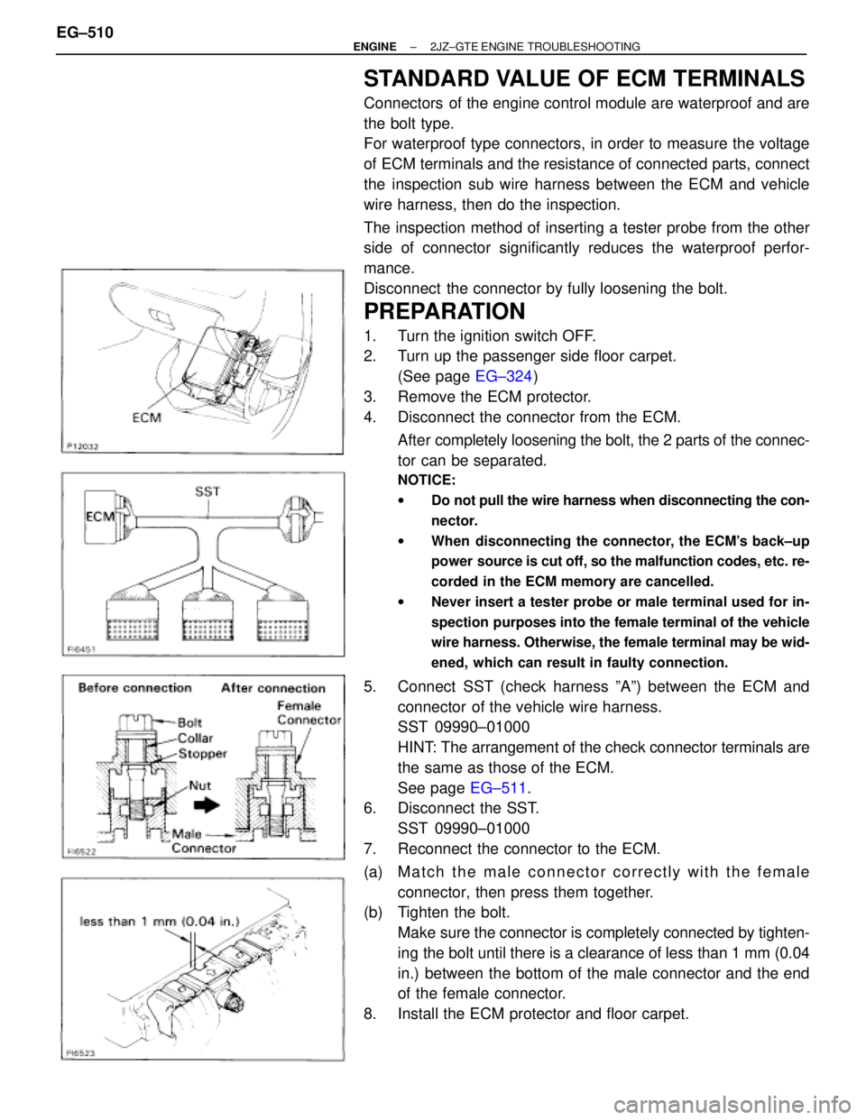
STANDARD VALUE OF ECM TERMINALS
Connectors of the engine control module are waterproof and are
the bolt type.
For waterproof type connectors, in order to measure the voltage
of ECM terminals and the resistance of connected parts, connect
the inspection sub wire harness between the ECM and vehicle
wire harness, then do the inspection.
The inspection method of inserting a tester probe from the other
side of connector significantly reduces the waterproof perfor-
mance.
Disconnect the connector by fully loosening the bolt.
PREPARATION
1. Turn the ignition switch OFF.
2. Turn up the passenger side floor carpet.
(See page EG±324)
3. Remove the ECM protector.
4. Disconnect the connector from the ECM.
After completely loosening the bolt, the 2 parts of the connec-
tor can be separated.
NOTICE:
wDo not pull the wire harness when disconnecting the con-
nector.
wWhen disconnecting the connector, the ECM's back±up
power source is cut off, so the malfunction codes, etc. re-
corded in the ECM memory are cancelled.
wNever insert a tester probe or male terminal used for in-
spection purposes into the female terminal of the vehicle
wire harness. Otherwise, the female terminal may be wid-
ened, which can result in faulty connection.
5. Connect SST (check harness ºAº) between the ECM and
connector of the vehicle wire harness.
SST 09990±01000
HINT: The arrangement of the check connector terminals are
the same as those of the ECM.
See page EG±511.
6. Disconnect the SST.
SST 09990±01000
7. Reconnect the connector to the ECM.
(a) M a t c h t h e m a l e connector correctly with the female
connector, then press them together.
(b) Tighten the bolt.
Make sure the connector is completely connected by tighten-
ing the bolt until there is a clearance of less than 1 mm (0.04
in.) between the bottom of the male connector and the end
of the female connector.
8. Install the ECM protector and floor carpet. EG±510
± ENGINE2JZ±GTE ENGINE TROUBLESHOOTING
Page 160 of 878
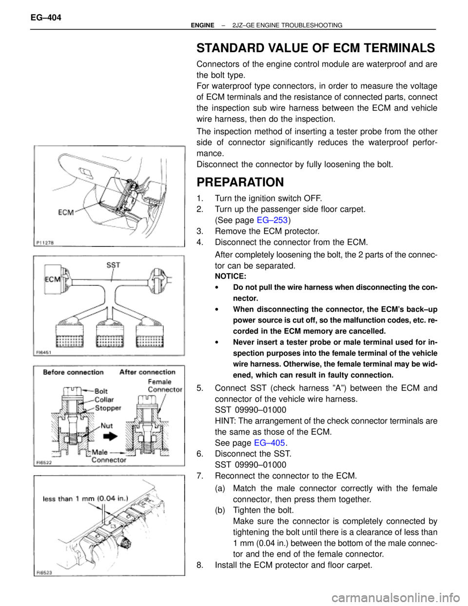
STANDARD VALUE OF ECM TERMINALS
Connectors of the engine control module are waterproof and are
the bolt type.
For waterproof type connectors, in order to measure the voltage
of ECM terminals and the resistance of connected parts, connect
the inspection sub wire harness between the ECM and vehicle
wire harness, then do the inspection.
The inspection method of inserting a tester probe from the other
side of connector significantly reduces the waterproof perfor-
mance.
Disconnect the connector by fully loosening the bolt.
PREPARATION
1. Turn the ignition switch OFF.
2. Turn up the passenger side floor carpet.
(See page EG±253)
3. Remove the ECM protector.
4. Disconnect the connector from the ECM.
After completely loosening the bolt, the 2 parts of the connec-
tor can be separated.
NOTICE:
wDo not pull the wire harness when disconnecting the con-
nector.
wWhen disconnecting the connector, the ECM's back±up
power source is cut off, so the malfunction codes, etc. re-
corded in the ECM memory are cancelled.
wNever insert a tester probe or male terminal used for in-
spection purposes into the female terminal of the vehicle
wire harness. Otherwise, the female terminal may be wid-
ened, which can result in faulty connection.
5. Connect SST (check harness ºAº) between the ECM and
connector of the vehicle wire harness.
SST 09990±01000
HINT: The arrangement of the check connector terminals are
the same as those of the ECM.
See page EG±405.
6. Disconnect the SST.
SST 09990±01000
7. Reconnect the connector to the ECM.
(a) Match the male connector correctly with the female
connector, then press them together.
(b) Tighten the bolt.
Make sure the connector is completely connected by
tightening the bolt until there is a clearance of less than
1 mm (0.04 in.) between the bottom of the male connec-
tor and the end of the female connector.
8. Install the ECM protector and floor carpet. EG±404
± ENGINE2JZ±GE ENGINE TROUBLESHOOTING
Page 474 of 878
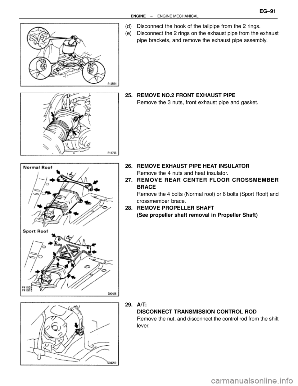
(d) Disconnect the hook of the tailpipe from the 2 rings.
(e) Disconnect the 2 rings on the exhaust pipe from the exhaust
pipe brackets, and remove the exhaust pipe assembly.
25. REMOVE NO.2 FRONT EXHAUST PIPE
Remove the 3 nuts, front exhaust pipe and gasket.
26. REMOVE EXHAUST PIPE HEAT INSULATOR
Remove the 4 nuts and heat insulator.
27. R E M O V E R E A R C E N T E R F L O O R C R O S S M E M B E R
BRACE
Remove the 4 bolts (Normal roof) or 6 bolts (Sport Roof) and
crossmember brace.
28. REMOVE PROPELLER SHAFT
(See propeller shaft removal in Propeller Shaft)
29. A/T:
DISCONNECT TRANSMISSION CONTROL ROD
Remove the nut, and disconnect the control rod from the shift
lever.
± ENGINEENGINE MECHANICALEG±91
Page 613 of 878

12
TROUBLESHOOTING
HOW TO REPLACE TERMINAL
(with terminal retainer or secondary locking
device)
1. PREPARE THE SPECIAL TOOL
HINT: To remove the terminal from the connector, please
construct and use the special tool or like object shown
on the left.
2. DISCONNECT CONNECTOR
3. DISENGAGE THE SECONDARY LOCKING DEVICE OR
TERMINAL RETAINER.
(a) Locking device must be disengaged before the
terminal locking clip can be released and the terminal
removed from the connector.
(b) Use a special tool or the terminal pick to unlock the
secondary locking device or terminal retainer.
NOTICE:
Do not remove the terminal retainer from connector body.
For Non±Waterproof Type Connector
HINT: The needle insertion position varies according
to the connector's shape (number of terminals
etc.), so check the position before inserting it.
ªCase 1º
Raise the terminal retainer up to the temporary
lock position.
ªCase 2º
Open the secondary locking device.
Page 614 of 878

13
For Waterproof Type Connector
HINT: Terminal retainer color is different
according to connector body.
Example:
Terminal Retainer
: Connector Body
Black or White : Gray
Black or White : Dark Gray
Gray or White : Black
ªCase 1º
Type where terminal retainer is pulled up
to the temporary lock position (Pull Type).
Insert the special tool into the terminal
retainer access hole ( Mark) and pull the
terminal retainer up to the temporary lock
position.
HINT: The needle insertion position varies
according to the connector's shape
(Number of terminals etc.), so check the
position before inserting it.
ªCase 2º
Type which cannot be pulled as far as
Power Lock insert the tool straight into the
access hole of terminal retainer as shown.
Page 719 of 878
120
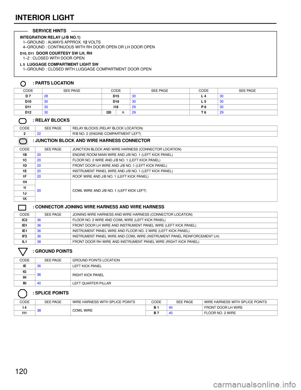
INTERIOR LIGHT
INTEGRATION RELAY (J/B NO.1)
1±GROUND : ALWAYS APPROX. 12 VOLTS
4±GROUND : CONTINUOUS WITH RH DOOR OPEN OR LH DOOR OPEN
D10, D11 DOOR COURTESY SW LH, RH
1±2 : CLOSED WITH DOOR OPEN
L 5 LUGGAGE COMPARTMENT LIGHT SW
1±GROUND : CLOSED WITH LUGGAGE COMPARTMENT DOOR OPEN
: PARTS LOCATION
CODESEE PAGECODESEE PAGECODESEE PAGE
D 728D1530L 430
D1030D1630L 530
D1130I1829P 630
D1230I20A29T 629
: RELAY BLOCKS
CODESEE PAGERELAY BLOCKS (RELAY BLOCK LOCATION)
222R/B NO. 2 (ENGINE COMPARTMENT LEFT)
: JUNCTION BLOCK AND WIRE HARNESS CONNECTOR
CODESEE PAGEJUNCTION BLOCK AND WIRE HARNESS (CONNECTOR LOCATION)
1B20ENGINE ROOM MAIN WIRE AND J/B NO. 1 (LEFT KICK PANEL)
1C20FLOOR NO. 2 WIRE AND J/B NO. 1 (LEFT KICK PANEL)
1D20FRONT DOOR LH WIRE AND J/B NO. 1 (LEFT KICK PANEL)
1E20INSTRUMENT PANEL WIRE AND J/B NO. 1 (LEFT KICK PANEL)
1F20ROOF WIRE AND J/B NO. 1 (LEFT KICK PANEL)
1H
1I20COWL WIRE AND J/B NO 1 (LEFT KICK LEFT)1J20COWL WIRE AND J/B NO. 1 (LEFT KICK LEFT)
1K
: CONNECTOR JOINING WIRE HARNESS AND WIRE HARNESS
CODESEE PAGEJOINING WIRE HARNESS AND WIRE HARNESS (CONNECTOR LOCATION)
IC236FLOOR NO. 2 WIRE AND COWL WIRE (LEFT KICK PANEL)
ID136FRONT DOOR LH WIRE AND INSTRUMENT PANEL WIRE (LEFT KICK PANEL)
IE136INSTRUMENT PANEL WIRE AND FLOOR NO. 2 WIRE (LEFT KICK PANEL)
IF236INSTRUMENT PANEL WIRE AND COWL WIRE (INSTRUMENT PANEL REINFORCEMENT LH)
IL138FRONT DOOR RH WIRE AND INSTRUMENT PANEL WIRE (RIGHT KICK PANEL)
: GROUND POINTS
CODESEE PAGEGROUND POINTS LOCATION
IE36LEFT KICK PANEL
IG36RIGHT KICK PANELIH36RIGHT KICK PANEL
BI40LEFT QUARTER PILLAR
: SPLICE POINTS
CODESEE PAGEWIRE HARNESS WITH SPLICE POINTSCODESEE PAGEWIRE HARNESS WITH SPLICE POINTS
I 438COWL WIREB 140FRONT DOOR LH WIRE
I1138COWL WIREB 740FLOOR NO. 2 WIRE
SERVICE HINTS
Page 839 of 878
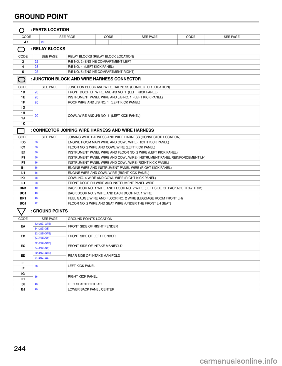
244
GROUND POINT
: PARTS LOCATION
CODESEE PAGECODESEE PAGECODESEE PAGE
J 129
: RELAY BLOCKS
CODESEE PAGERELAY BLOCKS (RELAY BLOCK LOCATION)
222R/B NO. 2 (ENGINE COMPARTMENT LEFT
423R/B NO. 4 (LEFT KICK PANEL)
523R/B NO. 5 (ENGINE COMPARTMENT RIGHT)
: JUNCTION BLOCK AND WIRE HARNESS CONNECTOR
CODESEE PAGEJUNCTION BLOCK AND WIRE HARNESS (CONNECTOR LOCATION)
1D20FRONT DOOR LH WIRE AND J/B NO. 1 (LEFT KICK PANEL)
1E20INSTRUMENT PANEL WIRE AND J/B NO. 1 (LEFT KICK PANEL)
1F20ROOF WIRE AND J/B NO. 1 (LEFT KICK PANEL)
1G
1H20COWL WIRE AND J/B NO 1 (LEFT KICK PANEL)1J20COWL WIRE AND J/B NO. 1 (LEFT KICK PANEL)
1K
: CONNECTOR JOINING WIRE HARNESS AND WIRE HARNESS
CODESEE PAGEJOINING WIRE HARNESS AND WIRE HARNESS (CONNECTOR LOCATION)
IB536ENGINE ROOM MAIN WIRE AND COWL WIRE (RIGHT KICK PANEL)
IC136FLOOR NO. 2 WIRE AND COWL WIRE (LEFT KICK PANEL)
IE136INSTRUMENT PANEL WIRE AND FLOOR NO. 2 WIRE (LEFT KICK PANEL)
IF136INSTRUMENT PANEL WIRE AND COWL WIRE (INSTRUMENT PANEL REINFORCEMENT LH)
IF336INSTRUMENT PANEL WIRE AND COWL WIRE (RIGHT KICK PANEL)
II138ENGINE WIRE AND INSTRUMENT PANEL WIRE (RIGHT KICK PANEL)
IJ138ENGINE WIRE AND COWL WIRE (RIGHT KICK PANEL)
IK138COWL NO. 4 WIRE AND COWL WIRE (RIGHT KICK PANEL)
IL138FRONT DOOR RH WIRE AND INSTRUMENT PANEL WIRE
BM140BACK DOOR NO. 1 WIRE AND FLOOR NO. 2 WIRE (LEFT SIDE OF PACKAGE TRAY TRIM)
BO140BACK DOOR NO. 2 WIRE AND BACK DOOR NO. 1 WIRE
BP140FUEL GAUGE WIRE AND FLOOR NO. 2 WIRE (LUGGAGE ROOM FRONT LH)
BQ142FLOOR NO. 2 WIRE AND SEAT WIRE (UNDER THE FRONT LH SEAT)
: GROUND POINTS
CODESEE PAGEGROUND POINTS LOCATION
EA32 (2JZ±GTE)FRONT SIDE OF RIGHT FENDEREA34 (2JZ±GE)FRONT SIDE OF RIGHT FENDER
EB32 (2JZ±GTE)FRONT SIDE OF LEFT FENDEREB34 (2JZ±GE)FRONT SIDE OF LEFT FENDER
EC32 (2JZ±GTE)FRONT SIDE OF INTAKE MANIFOLDEC34 (2JZ±GE)FRONT SIDE OF INTAKE MANIFOLD
ED32 (2JZ±GTE)REAR SIDE OF INTAKE MANIFOLDED34 (2JZ±GE)REAR SIDE OF INTAKE MANIFOLD
IE36LEFT KICK PANELIF36LEFT KICK PANEL
IG36RIGHT KICK PANELIH36RIGHT KICK PANEL
BI40LEFT QUARTER PILLAR
BJ40LOWER BACK PANEL CENTER