Page 186 of 878
 Disconnect the EFI No.1 fuse (30A) for 10 sec. or more, with IG switch OFF.
Initiate test mode (Connect terminal TE2 and E1 of data link connector 2
with IG switch OFF).
(2) S")
See page
EG±421
(1) Disconnect the EFI No.1 fuse (30A) for 10 sec. or more, with IG switch OFF.
Initiate test mode (Connect terminal TE2 and E1 of data link connector 2
with IG switch OFF).
(2) Start the engine and warm up with all ACC switched OFF.
(3) Idle the engine for 5 min.
(After the engine is started, do not depress the accelerator pedal.)
(4) If the malfunction is not detected during idling, racing the engine without any load at
approx. 2,000 rpm for 60 sec.
HINT: If a malfunction exists, the malfunction indicator lamp will light up during the 5 min. idling
period or within 60 sec. of starting racing.
NOTICE: If the conditions in this test are not strictly followed, detection of the malfunction
will not be possible.
CIRCUIT DESCRIPTION (Cont'd)
DIAGNOSTIC TROUBLE CODE DETECTION DRIVING PATTERN
Purpose of the driving pattern.
(a) To simulate diagnostic trouble code detecting condition after diagnostic trouble code is recorded.
(b) To check that the malfunction is corrected when the repair is completed confirming that diagnostic
trouble code is no longer detected.
Malfunction: Open or Short in Injector circuit, Injector Leak or Blockage.
WIRING DIAGRAM
See page EG±421 for the WIRING DIAGRAM.
*: Only for California specification vehicles
EG±430± ENGINE2JZ±GE ENGINE TROUBLESHOOTING
Page 191 of 878

DIAGNOSTIC TROUBLE CODE DETECTION DRIVING PATTERN
Purpose of the driving pattern.
(a) To simulate diagnostic trouble code detecting condition after diagnostic trouble cod")
CIRCUIT DESCRIPTION (Cont'd)
DIAGNOSTIC TROUBLE CODE DETECTION DRIVING PATTERN
Purpose of the driving pattern.
(a) To simulate diagnostic trouble code detecting condition after diagnostic trouble code is recorded.
(b) To check that the malfunction is corrected when the repair is completed confirming that diagnostic
trouble code is no longer detected.
(1) Disconnect the EFI No.1 fuse (30A) for 10 sec. or more, with IG switch OFF.
Initiate test mode (Connect terminal TE2 and E1 of data link connector 2 with
IG switch OFF).
(2) Start the engine and warm up with all ACC switch OFF.
(3) Deive the vehicle at 80 ~ 88 km/h (50 ~ 55 mph) for 10 min. or more.
(4) Stop at a safe place and idle the engine for 2 min. or less.
(5) Accelerate to 96 km/h (60 mph) with the throttle valve fully open.
HINT: If a malfunction exists, the malfunction indicator lamp will light up during step (5).
NOTICE: If the conditions in this test are not strictly followed, detection of the malfunction
will not be possible.
Malfunction: Open or Short in Sub Heated Oxygen Sensor
± ENGINE2JZ±GE ENGINE TROUBLESHOOTINGEG±435
Page 210 of 878
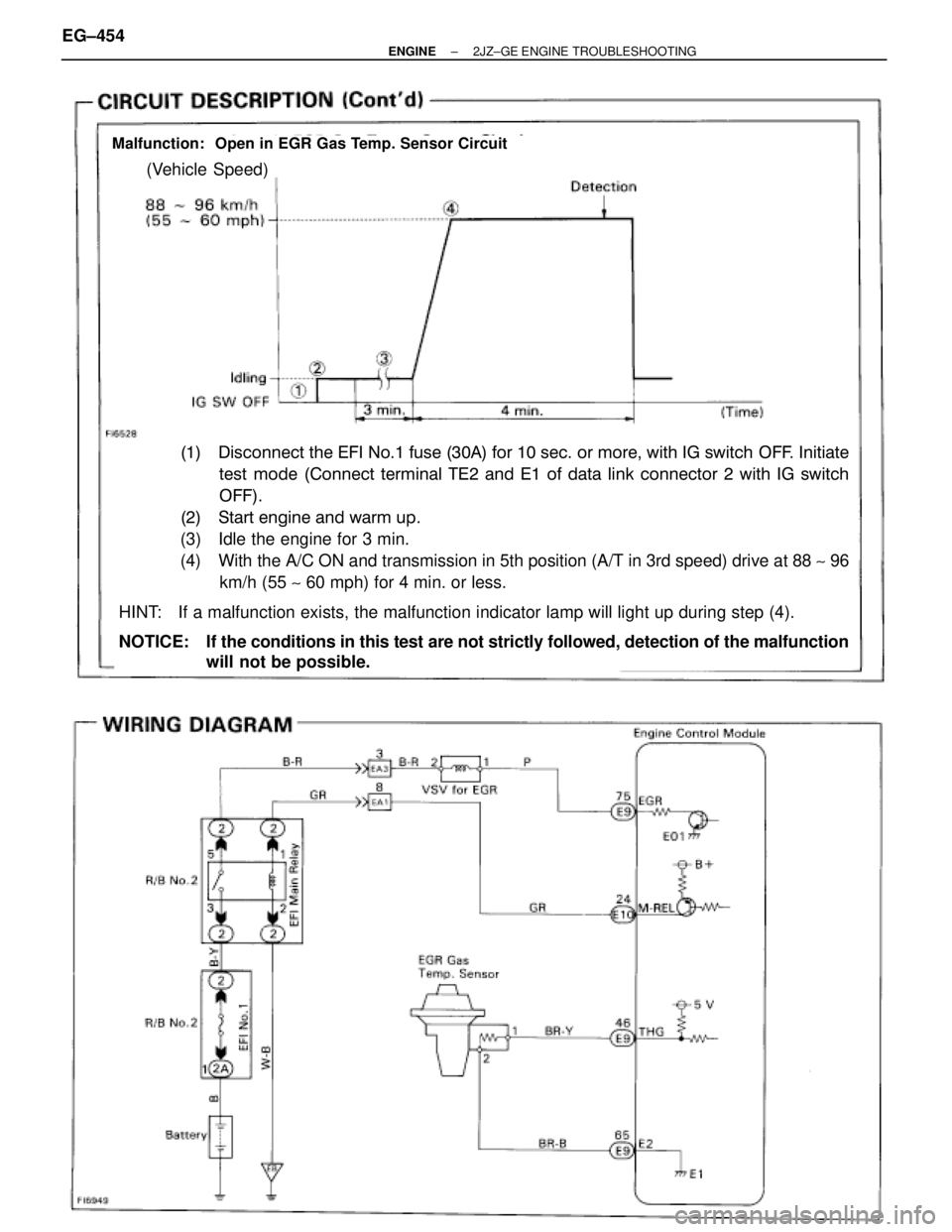
Malfunction: Open in EGR Gas Temp. Sensor Circuit
(Vehicle Speed)
(1)�Disconnect the EFI No.1 fuse (30A) for 10 sec. or more, with IG switch OFF. Initiate
���test mode (Connect terminal TE2 and E1 of data link connector 2 with IG switch
���OFF).
(2)�Start engine and warm up.
(3) Idle the engine for 3 min.
(4) With the A/C ON and transmission in 5th position (A/T in 3rd speed) drive at 88 ~ 96
km/h (55 ~ 60 mph) for 4 min. or less.
HINT: If a malfunction exists, the malfunction indicator lamp will light up during step (4).
NOTICE: If the conditions in this test are not strictly followed, detection of the malfunction
will not be possible. EG±454
± ENGINE2JZ±GE ENGINE TROUBLESHOOTING
Page 223 of 878
Check IGN fuse.
Remove IGN fuse from J/B No.1.
Check continuity of IGN fuse.
Continuity
Check for short in the harness and all the com-
ponents connected to IGN fuse (See Electrical
Wiring Diagram).
Check ignition switch.
(1) Remove finish lower panel and finish lower
panel LH.
(2) Remove heater to register duct No.2.
Check continuity between terminals.
Replace ignition switch.
Check and repair harness and connector between
battery and ignition switch, ignition switch and en-
gine control module.
± ENGINE2JZ±GE ENGINE TROUBLESHOOTINGEG±467
Page 224 of 878
Check voltage between terminal M±REL of engine control module connector
and body ground.
Turn ignition switch ON.
Measure voltage between terminal M±REL of en-
gine control module connector and body ground.
Voltage: 9 Ð 14 V
Check and replace engine control module.
Check EFI No.1 Fuse.
Remove EFI No.1 fuse from R/B No.2.
Check continuity of EFI No.1 fuse.
Continuity
Check for short in the harness and all the compo-
nents connected to EFI No.1 fuse (See Electrical
Wiring Diagram).
EG±468± ENGINE2JZ±GE ENGINE TROUBLESHOOTING
Page 225 of 878
Check EFI main relay.
Remove EFI main relay from R/B No.2.
Check continuity between terminals of EFI main
relay shown below.
Replace EFI main relay.
(1) Apply battery voltage between terminals 1
and 2.
(2) Check continuity between terminals 3 and 5.
Repair or replace harness or connector.
Check and repair harness or connector between
EFI No.1 fuse and battery.
Check for open and short in harness and connector between terminal M±REL
of engine control module and body ground(See page
IN±30).
Terminals 3 and 5
Terminals 3 and 5
Terminals 1 and 2
Open
Continuity
Continuity
(Reference value 72 �)
± ENGINE2JZ±GE ENGINE TROUBLESHOOTINGEG±469
Page 227 of 878
INSPECTION PROCEDURE
Check EFI No.1 Fuse.
Remove EFI No.1 fuse from R/B No.2.
Check continuity of EFI No.1 fuse.
Continuity
Check for short in the harness and all the com-
ponents connected to EFI No.1 fuse (See Electri-
cal Wiring Diagram).
Connect SST (check harness ªAº).
(See page EG±404)
SST 09990±01000
Measure voltage between terminal BATT of en-
gine control module connector and body ground.
Voltage: 9 Ð 14 V
Check and replace engine control module.
Check and repair harness or connector between
engine control module and EFI No.1 fuse, EFI No.1
fuse and battery.
Proceed to next circuit inspection shown on matrix
chart (See page
EG±408).
Check voltage between terminal BATT of engine control module connector
and body ground.
Are the diagnostic trouble codes still in the memory when the ignition switch
is turned OFF?
± ENGINE2JZ±GE ENGINE TROUBLESHOOTINGEG±471
Page 229 of 878
INSPECTION PROCEDURE
(See page EG±404)
Check voltage between terminals # 10 ~ 60 of engine control module and
body ground.
(1) Connect SST check harness ªAº).
(See page EG±404)
SST 09990±01000
(2) Turn ignition switch ON.
Measure voltage between terminals #10
~ 60 of
engine control module and body ground.
Voltage: 9 Ð 14 V
Check for short in the harness and all the compo-
nents connected to AM2 fuse.
Remove AM2 fuse from R/B No.2.
Check continuity of AM2 fuse.
Continuity
Check and repair harness or connector between en-
gine control module and battery.
Check AM2 Fuse.
± ENGINE2JZ±GE ENGINE TROUBLESHOOTINGEG±473
.")

 Apply battery voltage between terminals 1
and 2")


Check voltage between terminals # 10 ~ 60 of engine control module and
body ground.
(1) Connect SST check harness ªAº).
(See page EG±404)
SST 09990±01000
(")