1985 BMW 3 SERIES brake drum
[x] Cancel search: brake drumPage 4 of 228
0•4Introduction
The E30 3-Series range first became
available in the UK in March 1983, and
continued in production until April 1991, when
the revised E36 3-Series range (not covered
by this manual) was introduced. Convertible
and Touring (Estate) models were introduced
for 1988, and these models have continued in
E30 form to date.
The E28 5-Series models were introduced
in October 1981, and were superseded in
June 1988 by the revised E34 5-Series range,
Touring versions of which became available
from March 1992. Throughout this manual,
E28 models are also referred to as “old-
shape”, while E34 models are designated
“new-shape”.
The models covered by this manual are
equipped with single overhead cam in-line
four- and six-cylinder engines. Early 316 and
518 models are fitted with carburettors, but all
other models are fitted with fuel injection
systems. Transmissions are a five-speed
manual, or three- or four-speed automatic.
The transmission is mounted to the back of
the engine, and power is transmitted to the
fully-independent rear axle through a two-
piece propeller shaft. The final drive unit is
bolted solidly to a frame crossmember, and
drives the rear wheels through driveshaftsequipped with inner and outer constant
velocity joints.
The front suspension is of MacPherson
strut type, with the coil spring/shock absorber
unit making up the upper suspension link. The
rear suspension is made up of coil spring-
over-shock absorber struts, or coil springs
and conventional shock absorbers,
depending on model.
The brakes are disc type at the front, with
either drums or discs at the rear, depending
on model. Servo assistance is standard on all
models. Some later models are equipped with
an Anti-lock Braking System (ABS).
All models are manufactured to fine limits,
and live up to the BMW reputation of quality
workmanship. Although many of the models
covered by this manual appear complex at
first sight, they should present no problems to
the home mechanic.
Note for UK readers
The greater part of this manual was
originally written in the USA. Some of the
photographs used are of American-market
models, but the procedures given are fully
applicable to right-hand-drive models (or have
been amended where necessary).
Acknowledgements
Thanks are due to Champion Spark Plug,
who supplied the illustrations showing spark
plug conditions. Thanks are also due to
Sykes-Pickavant Limited, who provided some
of the workshop tools, and to all those people
at Sparkford who helped in the production of
this manual. Technical writers who
contributed to this project include Robert
Maddox, Mark Ryan and Mike Stubblefield.
We take great pride in the accuracy of
information given in this manual, but
vehicle manufacturers make alterations
and design changes during the production
run of a particular vehicle of which they do
not inform us. No liability can be accepted
by the authors or publishers for loss,
damage or injury caused by any
errors in, or omissions from, the
information given.
Project vehicles
The main project vehicle used in the
preparation of this manual for the UK market
was a 1988 BMW 318i with an M40/B18
engine.
Introduction to the BMW 3- and 5-Series
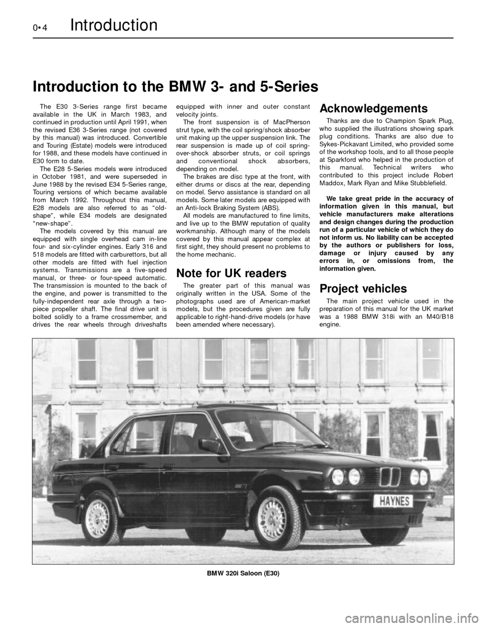
BMW 320i Saloon (E30)
Page 6 of 228

0•6Safety First!
Working on your car can be dangerous.
This page shows just some of the potential
risks and hazards, with the aim of creating a
safety-conscious attitude.
General hazards
Scalding
• Don’t remove the radiator or expansion
tank cap while the engine is hot.
• Engine oil, automatic transmission fluid or
power steering fluid may also be dangerously
hot if the engine has recently been running.
Burning
• Beware of burns from the exhaust system
and from any part of the engine. Brake discs
and drums can also be extremely hot
immediately after use.
Crushing
• When working under or near
a raised vehicle,
always
supplement the
jack with axle
stands, or use
drive-on
ramps.
Never
venture
under a car which
is only supported by a jack.
• Take care if loosening or tightening high-
torque nuts when the vehicle is on stands.
Initial loosening and final tightening should
be done with the wheels on the ground.
Fire
• Fuel is highly flammable; fuel vapour is
explosive.
• Don’t let fuel spill onto a hot engine.
• Do not smoke or allow naked lights
(including pilot lights) anywhere near a
vehicle being worked on. Also beware of
creating sparks
(electrically or by use of tools).
• Fuel vapour is heavier than air, so don’t
work on the fuel system with the vehicle over
an inspection pit.
• Another cause of fire is an electrical
overload or short-circuit. Take care when
repairing or modifying the vehicle wiring.
• Keep a fire extinguisher handy, of a type
suitable for use on fuel and electrical fires.
Electric shock
• Ignition HT
voltage can be
dangerous,
especially to
people with heart
problems or a
pacemaker. Don’t
work on or near the
ignition system with
the engine running or
the ignition switched on.• Mains voltage is also dangerous. Make
sure that any mains-operated equipment is
correctly earthed. Mains power points should
be protected by a residual current device
(RCD) circuit breaker.
Fume or gas intoxication
• Exhaust fumes are
poisonous; they often
contain carbon
monoxide, which is
rapidly fatal if inhaled.
Never run the
engine in a
confined space
such as a garage
with the doors shut.
• Fuel vapour is also
poisonous, as are the vapours from some
cleaning solvents and paint thinners.
Poisonous or irritant substances
• Avoid skin contact with battery acid and
with any fuel, fluid or lubricant, especially
antifreeze, brake hydraulic fluid and Diesel
fuel. Don’t syphon them by mouth. If such a
substance is swallowed or gets into the eyes,
seek medical advice.
• Prolonged contact with used engine oil can
cause skin cancer. Wear gloves or use a
barrier cream if necessary. Change out of oil-
soaked clothes and do not keep oily rags in
your pocket.
• Air conditioning refrigerant forms a
poisonous gas if exposed to a naked flame
(including a cigarette). It can also cause skin
burns on contact.
Asbestos
• Asbestos dust can cause cancer if inhaled
or swallowed. Asbestos may be found in
gaskets and in brake and clutch linings.
When dealing with such components it is
safest to assume that they contain asbestos.
Special hazards
Hydrofluoric acid
• This extremely corrosive acid is formed
when certain types of synthetic rubber, found
in some O-rings, oil seals, fuel hoses etc, are
exposed to temperatures above 400
0C. The
rubber changes into a charred or sticky
substance containing the acid. Once formed,
the acid remains dangerous for years. If it
gets onto the skin, it may be necessary to
amputate the limb concerned.
• When dealing with a vehicle which has
suffered a fire, or with components salvaged
from such a vehicle, wear protective gloves
and discard them after use.
The battery
• Batteries contain sulphuric acid, which
attacks clothing, eyes and skin. Take care
when topping-up or carrying the battery.
• The hydrogen gas given off by the battery
is highly explosive. Never cause a spark or
allow a naked light nearby. Be careful when
connecting and disconnecting battery
chargers or jump leads.
Air bags
• Air bags can cause injury if they go off
accidentally. Take care when removing the
steering wheel and/or facia. Special storage
instructions may apply.
Diesel injection equipment
• Diesel injection pumps supply fuel at very
high pressure. Take care when working on
the fuel injectors and fuel pipes.
Warning: Never expose the hands,
face or any other part of the body
to injector spray; the fuel can
penetrate the skin with potentially fatal
results.
Remember...
DO
• Do use eye protection when using power
tools, and when working under the vehicle.
• Do wear gloves or use barrier cream to
protect your hands when necessary.
• Do get someone to check periodically
that all is well when working alone on the
vehicle.
• Do keep loose clothing and long hair well
out of the way of moving mechanical parts.
• Do remove rings, wristwatch etc, before
working on the vehicle – especially the
electrical system.
• Do ensure that any lifting or jacking
equipment has a safe working load rating
adequate for the job.
A few tips
DON’T
• Don’t attempt to lift a heavy component
which may be beyond your capability – get
assistance.
• Don’t rush to finish a job, or take
unverified short cuts.
• Don’t use ill-fitting tools which may slip
and cause injury.
• Don’t leave tools or parts lying around
where someone can trip over them. Mop
up oil and fuel spills at once.
• Don’t allow children or pets to play in or
near a vehicle being worked on.
Page 12 of 228

Fuel system
Idle speed
3-Series, E30
316 with M10/B18 engine . . . . . . . . . . . . . . . . . . . . . . . . . . . . . . . . 850 ± 50 rpm
316i with M40/B16 engine . . . . . . . . . . . . . . . . . . . . . . . . . . . . . . . 800 ± 40 rpm
318i with M10/B18 engine (manual transmission) . . . . . . . . . . . . . 850 ± 50 rpm
318i with M10/B18 engine (automatic transmission) . . . . . . . . . . . 750 ± 50 rpm
318i with M40/B18 engine . . . . . . . . . . . . . . . . . . . . . . . . . . . . . . . 800 ± 40 rpm
320i with M20/B20 engine (L-Jetronic) . . . . . . . . . . . . . . . . . . . . . . 800 ± 50 rpm
320i with M20/B20 engine (Motronic) . . . . . . . . . . . . . . . . . . . . . . . 760 ± 40 rpm
325i with M20/B25 engine . . . . . . . . . . . . . . . . . . . . . . . . . . . . . . . 760 ± 40 rpm
5-Series, E28 (“old-shape”)
518 and 518i with M10/B18 engine . . . . . . . . . . . . . . . . . . . . . . . . 800 ± 50 rpm
All other models . . . . . . . . . . . . . . . . . . . . . . . . . . . . . . . . . . . . . . . 850 ± 50 rpm
5-Series, E34 (“new-shape”)
518i with M40/B18 engine . . . . . . . . . . . . . . . . . . . . . . . . . . . . . . . 800 ± 40 rpm
520i with M20/B20M engine . . . . . . . . . . . . . . . . . . . . . . . . . . . . . . 760 ± 40 rpm
525i with M20/B25M engine . . . . . . . . . . . . . . . . . . . . . . . . . . . . . . 760 ± 40 rpm
530i with M30/B30M engine . . . . . . . . . . . . . . . . . . . . . . . . . . . . . . 800 ± 50 rpm
535i with M30/B35M engine . . . . . . . . . . . . . . . . . . . . . . . . . . . . . . 850 ± 50 rpm
CO% at 3000 rpm
3-Series, E30
316 with M10/B18 engine . . . . . . . . . . . . . . . . . . . . . . . . . . . . . . . . 0.5 to 1.0
316i and 318i with M40/B16 engine . . . . . . . . . . . . . . . . . . . . . . . . 0.7 ± 0.5
318i with M10/B18 engine . . . . . . . . . . . . . . . . . . . . . . . . . . . . . . . 1.0 maximum
320i with M20/B20 engine (L-Jetronic) . . . . . . . . . . . . . . . . . . . . . . 1.0 ± 0.5
320i with M20/B20 engine (Motronic) . . . . . . . . . . . . . . . . . . . . . . . 0.7 ± 0.5
325i with M20/B25 engine . . . . . . . . . . . . . . . . . . . . . . . . . . . . . . . 1.0 ± 0.5
5-Series, E28 (“old-shape”)
518 and 518i with M10/B18 engine . . . . . . . . . . . . . . . . . . . . . . . . 1.0 maximum
525i with M30/B25 engine . . . . . . . . . . . . . . . . . . . . . . . . . . . . . . . 1.0 ± 0.5
528i with M30/B28 engine . . . . . . . . . . . . . . . . . . . . . . . . . . . . . . . 1.5 maximum
535i with M30/B34 engine . . . . . . . . . . . . . . . . . . . . . . . . . . . . . . . 0.3 to 1.5
M535i with M30/B34 engine . . . . . . . . . . . . . . . . . . . . . . . . . . . . . . 0.3 to 1.5
5-Series, E34 (“new-shape”)
All models . . . . . . . . . . . . . . . . . . . . . . . . . . . . . . . . . . . . . . . . . . . . 0.7 ± 0.5
Air filter element
M10 engines . . . . . . . . . . . . . . . . . . . . . . . . . . . . . . . . . . . . . . . . . . . . Champion W155 (round) or U504 (square)
M20 engines . . . . . . . . . . . . . . . . . . . . . . . . . . . . . . . . . . . . . . . . . . . . Champion U504 or U527
M30 engines . . . . . . . . . . . . . . . . . . . . . . . . . . . . . . . . . . . . . . . . . . . . Champion U504 or U527
M40 engines . . . . . . . . . . . . . . . . . . . . . . . . . . . . . . . . . . . . . . . . . . . . Champion U527
Fuel filter (all fuel injection engines) . . . . . . . . . . . . . . . . . . . . . . . . . . . . Champion L206
Ignition system
Spark plug type
M10, M20 and M30 engines . . . . . . . . . . . . . . . . . . . . . . . . . . . . . . . . Champion N9YCC
M40 engines . . . . . . . . . . . . . . . . . . . . . . . . . . . . . . . . . . . . . . . . . . . . Champion C9YCC
Spark plug gap* . . . . . . . . . . . . . . . . . . . . . . . . . . . . . . . . . . . . . . . . . . . 0.8 mm
Spark plug (HT) leads . . . . . . . . . . . . . . . . . . . . . . . . . . . . . . . . . . . . . . . Champion type not available
* The spark plug gap quoted is that recommended by Champion for their specified plugs listed above. If spark plugs of any other type are to be
fitted, refer to their manufacturer’s spark plug gap recommendations.
Brakes
Disc brake pad thickness (minimum) . . . . . . . . . . . . . . . . . . . . . . . . . . . 2.0 mm
Drum brake shoe lining thickness (minimum) . . . . . . . . . . . . . . . . . . . . . 2.0 mm
Wiper blades
Windscreen
3-Series . . . . . . . . . . . . . . . . . . . . . . . . . . . . . . . . . . . . . . . . . . . . . . . . Champion X-5103
3-Series passenger side from 1991 . . . . . . . . . . . . . . . . . . . . . . . . . . Champion X-5103 (20 inch) or Champion X-5303 (21 inch)
5-Series, E28 (“old-shape”) . . . . . . . . . . . . . . . . . . . . . . . . . . . . . . . . Champion X-4503
5-Series, E34 (“new-shape”) . . . . . . . . . . . . . . . . . . . . . . . . . . . . . . . . Champion type not available
Tailgate
3-Series . . . . . . . . . . . . . . . . . . . . . . . . . . . . . . . . . . . . . . . . . . . . . . . . Champion X-4503
5-Series . . . . . . . . . . . . . . . . . . . . . . . . . . . . . . . . . . . . . . . . . . . . . . . . Champion type not available
1•2Servicing Specifications
Page 33 of 228
material is bonded to a metal plate or shoe -
the metal portion is not included in this
measurement. Always renew the pads on
both sides of the vehicle (in axle sets), even if
only one pad of the four is worn, or uneven
braking may result.
12Remove the calipers without
disconnecting the brake hoses (see Chap-
ter 9).
13Check the condition of the brake disc.
Look for score marks, deep scratches and
overheated areas (they will appear blue or
discoloured). If damage or wear is noted, the
disc can be removed and resurfaced by an
engineering workshop; otherwise, it will have
to be renewed. In either case, both discs
should be involved, even if only one is worn.
Refer to Chapter 9 for more detailed
inspection and repair procedures.
Drum brakes
14Refer to Chapter 9 and remove the rear
brake drums.
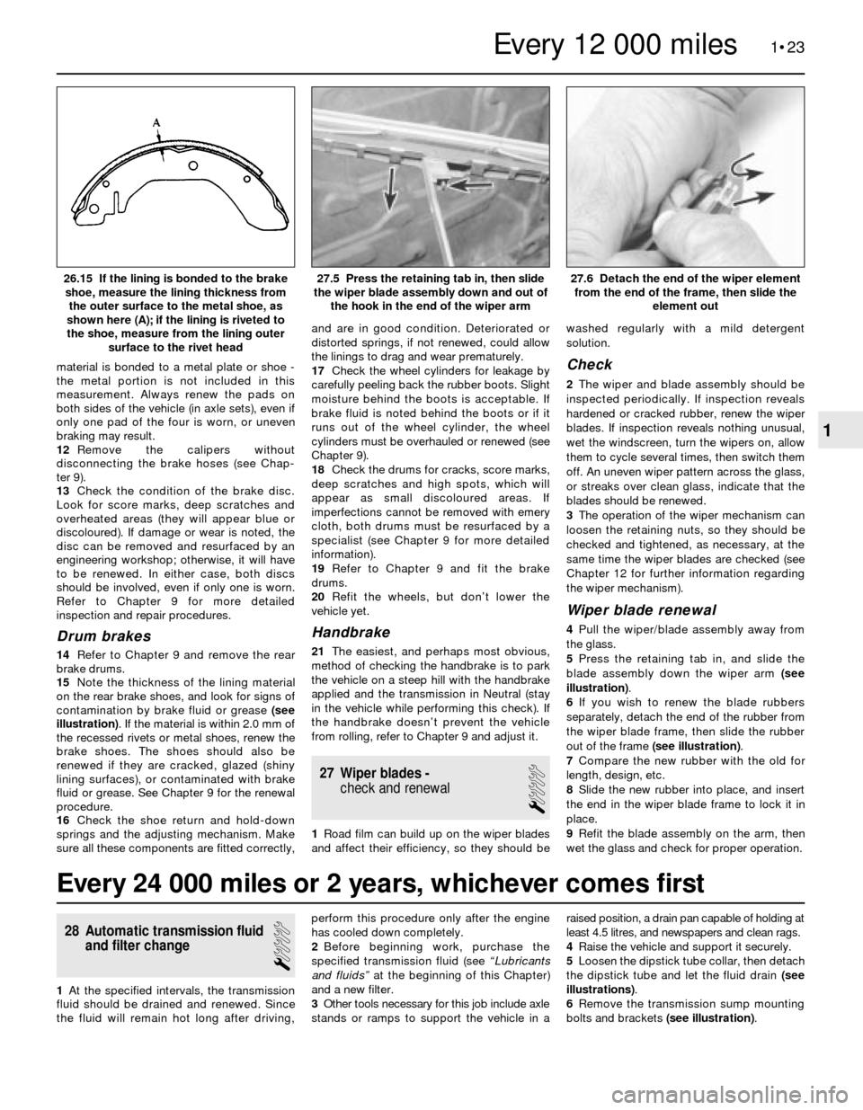
15Note the thickness of the lining material
on the rear brake shoes, and look for signs of
contamination by brake fluid or grease (see
illustration). If the material is within 2.0 mm of
the recessed rivets or metal shoes, renew the
brake shoes. The shoes should also be
renewed if they are cracked, glazed (shiny
lining surfaces), or contaminated with brake
fluid or grease. See Chapter 9 for the renewal
procedure.
16Check the shoe return and hold-down
springs and the adjusting mechanism. Make
sure all these components are fitted correctly,and are in good condition. Deteriorated or
distorted springs, if not renewed, could allow
the linings to drag and wear prematurely.
17Check the wheel cylinders for leakage by
carefully peeling back the rubber boots. Slight
moisture behind the boots is acceptable. If
brake fluid is noted behind the boots or if it
runs out of the wheel cylinder, the wheel
cylinders must be overhauled or renewed (see
Chapter 9).
18Check the drums for cracks, score marks,
deep scratches and high spots, which will
appear as small discoloured areas. If
imperfections cannot be removed with emery
cloth, both drums must be resurfaced by a
specialist (see Chapter 9 for more detailed
information).
19Refer to Chapter 9 and fit the brake
drums.
20Refit the wheels, but don’t lower the
vehicle yet.
Handbrake
21The easiest, and perhaps most obvious,
method of checking the handbrake is to park
the vehicle on a steep hill with the handbrake
applied and the transmission in Neutral (stay
in the vehicle while performing this check). If
the handbrake doesn’t prevent the vehicle
from rolling, refer to Chapter 9 and adjust it.
27 Wiper blades -
check and renewal
1
1Road film can build up on the wiper blades
and affect their efficiency, so they should bewashed regularly with a mild detergent
solution.
Check
2The wiper and blade assembly should be
inspected periodically. If inspection reveals
hardened or cracked rubber, renew the wiper
blades. If inspection reveals nothing unusual,
wet the windscreen, turn the wipers on, allow
them to cycle several times, then switch them
off. An uneven wiper pattern across the glass,
or streaks over clean glass, indicate that the
blades should be renewed.
3The operation of the wiper mechanism can
loosen the retaining nuts, so they should be
checked and tightened, as necessary, at the
same time the wiper blades are checked (see
Chapter 12 for further information regarding
the wiper mechanism).
Wiper blade renewal
4Pull the wiper/blade assembly away from
the glass.
5Press the retaining tab in, and slide the
blade assembly down the wiper arm (see
illustration).
6If you wish to renew the blade rubbers
separately, detach the end of the rubber from
the wiper blade frame, then slide the rubber
out of the frame (see illustration).
7Compare the new rubber with the old for
length, design, etc.
8Slide the new rubber into place, and insert
the end in the wiper blade frame to lock it in
place.
9Refit the blade assembly on the arm, then
wet the glass and check for proper operation.
1•23
27.6 Detach the end of the wiper element
from the end of the frame, then slide the
element out27.5 Press the retaining tab in, then slide
the wiper blade assembly down and out of
the hook in the end of the wiper arm26.15 If the lining is bonded to the brake
shoe, measure the lining thickness from
the outer surface to the metal shoe, as
shown here (A); if the lining is riveted to
the shoe, measure from the lining outer
surface to the rivet head
1
Every 12 000 miles
Every 24 000 miles or 2 years, whichever comes first
28 Automatic transmission fluid
and filter change
1
1At the specified intervals, the transmission
fluid should be drained and renewed. Since
the fluid will remain hot long after driving,perform this procedure only after the engine
has cooled down completely.
2Before beginning work, purchase the
specified transmission fluid (see “Lubricants
and fluids”at the beginning of this Chapter)
and a new filter.
3Other tools necessary for this job include axle
stands or ramps to support the vehicle in araised position, a drain pan capable of holding at
least 4.5 litres, and newspapers and clean rags.
4Raise the vehicle and support it securely.
5Loosen the dipstick tube collar, then detach
the dipstick tube and let the fluid drain (see
illustrations).
6Remove the transmission sump mounting
bolts and brackets (see illustration).
Page 129 of 228

9
General
Brake fluid type . . . . . . . . . . . . . . . . . . . . . . . . . . . . . . . . . . . . . . . . . . . . See Chapter 1
Disc brakes
Minimum brake pad thickness . . . . . . . . . . . . . . . . . . . . . . . . . . . . . . . . See Chapter 1
Brake disc minimum permissible thickness (wear limit)*
Front
3-Series
Solid discs . . . . . . . . . . . . . . . . . . . . . . . . . . . . . . . . . . . . . . . . . . 10.7 mm
Ventilated discs . . . . . . . . . . . . . . . . . . . . . . . . . . . . . . . . . . . . . . 20.0 mm
5-Series
Solid discs . . . . . . . . . . . . . . . . . . . . . . . . . . . . . . . . . . . . . . . . . . 10.0 mm
Ventilated discs . . . . . . . . . . . . . . . . . . . . . . . . . . . . . . . . . . . . . . 20.0 mm
Rear . . . . . . . . . . . . . . . . . . . . . . . . . . . . . . . . . . . . . . . . . . . . . . . . . . 8.0 mm
Brake disc minimum thickness after machining
Front
3-Series
Solid discs . . . . . . . . . . . . . . . . . . . . . . . . . . . . . . . . . . . . . . . . . . 11.1 mm
Ventilated discs . . . . . . . . . . . . . . . . . . . . . . . . . . . . . . . . . . . . . . 20.4 mm
5-Series
Solid discs . . . . . . . . . . . . . . . . . . . . . . . . . . . . . . . . . . . . . . . . . . 10.4 mm
Ventilated discs . . . . . . . . . . . . . . . . . . . . . . . . . . . . . . . . . . . . . . 20.4 mm
Rear . . . . . . . . . . . . . . . . . . . . . . . . . . . . . . . . . . . . . . . . . . . . . . . . . . 8.4 mm
Parallelism (difference between any two measurements) . . . . . . . . . . . 0.02 mm
Maximum disc run-out . . . . . . . . . . . . . . . . . . . . . . . . . . . . . . . . . . . . . . 0.2 mm
*Refer to marks cast into the disc (they supersede information printed here)
Brake pedal adjustments
Brake pedal/servo pushrod adjustment (A) (3-Series) . . . . . . . . . . . . . . 125 mm
Brake pedal height (pedal-to-bulkhead distance)
3-Series
Left-hand-drive . . . . . . . . . . . . . . . . . . . . . . . . . . . . . . . . . . . . . . . . 235 mm
Right-hand-drive . . . . . . . . . . . . . . . . . . . . . . . . . . . . . . . . . . . . . . . 273 mm
5-Series . . . . . . . . . . . . . . . . . . . . . . . . . . . . . . . . . . . . . . . . . . . . . . . . 245 mm
Stop-light switch adjustment (dimension A - see text) . . . . . . . . . . . . . . 5.0 mm to 6.0 mm
Handbrake
Handbrake shoe lining minimum thickness . . . . . . . . . . . . . . . . . . . . . . 1.5 mm
Handbrake lever travel . . . . . . . . . . . . . . . . . . . . . . . . . . . . . . . . . . . . . . 5 to 8 clicks
Chapter 9 Braking system
Anti-lock brake system (ABS) - general information . . . . . . . . . . . . . 2
Brake check . . . . . . . . . . . . . . . . . . . . . . . . . . . . . . . . See Chapter 1
Brake disc - inspection, removal and refitting . . . . . . . . . . . . . . . . . 5
Brake fluid level check . . . . . . . . . . . . . . . . . . . . . . . . See Chapter 1
Brake hoses and lines - inspection and renewal . . . . . . . . . . . . . . . . 15
Brake hydraulic system - bleeding . . . . . . . . . . . . . . . . . . . . . . . . . . 16
Brake pedal - adjustment . . . . . . . . . . . . . . . . . . . . . . . . . . . . . . . . . 13
Brake vacuum servo - check, removal and refitting . . . . . . . . . . . . . 8
Disc brake caliper - removal, overhaul and refitting . . . . . . . . . . . . . 4Disc brake pads - renewal . . . . . . . . . . . . . . . . . . . . . . . . . . . . . . . . 3
Drum brake shoes - renewal . . . . . . . . . . . . . . . . . . . . . . . . . . . . . . . 6
General information . . . . . . . . . . . . . . . . . . . . . . . . . . . . . . . . . . . . . . 1
Handbrake assembly - check, removal and refitting . . . . . . . . . . . . 12
Handbrake - adjustment . . . . . . . . . . . . . . . . . . . . . . . . . . . . . . . . . . 11
Handbrake cable(s) - renewal . . . . . . . . . . . . . . . . . . . . . . . . . . . . . . 10
Hydraulic brake servo - description, removal and refitting . . . . . . . . 9
Master cylinder - removal and refitting . . . . . . . . . . . . . . . . . . . . . . . 7
Stop-light switch - check and adjustment . . . . . . . . . . . . . . . . . . . . 14
9•1
Easy,suitable for
novice with little
experienceFairly easy,suitable
for beginner with
some experienceFairly difficult,
suitable for competent
DIY mechanic
Difficult,suitable for
experienced DIY
mechanicVery difficult,
suitable for expert
DIY or professional
Degrees of difficulty
Specifications Contents
Page 130 of 228

Torque wrench settingsNm
Front disc brake caliper
Caliper guide (mounting) bolts . . . . . . . . . . . . . . . . . . . . . . . . . . . . . . 30 to 35
Caliper bracket-to-strut housing bolts
3-Series, E30 . . . . . . . . . . . . . . . . . . . . . . . . . . . . . . . . . . . . . . . . . . 123
5-Series, E28 (“old-shape”) . . . . . . . . . . . . . . . . . . . . . . . . . . . . . . . 123
5-Series, E34 (“new-shape”) . . . . . . . . . . . . . . . . . . . . . . . . . . . . . . 110
Rear disc brake caliper
Caliper guide (mounting) bolts . . . . . . . . . . . . . . . . . . . . . . . . . . . . . . 30 to 35
Carrier-to-trailing arm bolts . . . . . . . . . . . . . . . . . . . . . . . . . . . . . . . . 67
Brake hose-to-caliper fitting . . . . . . . . . . . . . . . . . . . . . . . . . . . . . . . . . . 14 to 17
Master cylinder-to-brake servo nuts
3-Series . . . . . . . . . . . . . . . . . . . . . . . . . . . . . . . . . . . . . . . . . . . . . . . . 24
5-Series . . . . . . . . . . . . . . . . . . . . . . . . . . . . . . . . . . . . . . . . . . . . . . . . 25 to 29
Brake servo mounting nuts . . . . . . . . . . . . . . . . . . . . . . . . . . . . . . . . . . . 22 to 24
Hydraulic line-to-hydraulic brake servo threaded
fittings - 5-Series, E28 (“old-shape”) . . . . . . . . . . . . . . . . . . . . . . . . . . . 31
Wheel bolts . . . . . . . . . . . . . . . . . . . . . . . . . . . . . . . . . . . . . . . . . . . . . . . See Chapter 1
9•2 Braking system
1 General information
All 3-Series models, and 5-Series E28 (“old-
shape”) models, are equipped with front disc
brakes and either rear drum or rear disc
brakes. 5-Series E34 (“new-shape”) models
have disc brakes front and rear. Front and
rear brakes are self-adjusting on all models.
Some later models are equipped with an Anti-
lock Braking System (ABS); this is described
in Section 2.
Hydraulic system
The hydraulic system consists of two
separate circuits. The master cylinder has
separate reservoirs for the two circuits; in the
event of a leak or failure in one hydraulic
circuit, the other circuit will remain operative.
Brake servo
The vacuum brake servo, utilising engine
manifold vacuum and atmospheric pressure
to provide assistance to the hydraulically
operated brakes, is mounted on the bulkhead
in the engine compartment.
A hydraulic brake servo system is used on
5-Series E28 models. This system uses
hydraulic pressure from the power steering
pump to assist braking.
Handbrake
The handbrake operates the rear brakes,
and is cable-operated via a lever mounted in
the centre console. The handbrake assembly
on rear drum brake models is part of the rear
drum brake assembly, and is self-adjusting.
On rear disc brake models, the handbrake
uses a pair of brake shoes located inside the
centre portion of the rear brake disc, and is
manually-adjusted.
Brake pad wear warning system
The brake pad wear warning system is
linked to a red warning light in the instrumentcluster, which comes on when the brake pads
have worn down to the point at which they
require renewal. DO NOT ignore this reminder.
If you don’t renew the pads shortly after the
brake pad wear warning light comes on, the
brake discs will be damaged.
On some models, the brake pad wear
warning system also includes an early
warning light that comes on only when the
brake pedal is depressed, letting you know in
advance that the pads need to be renewed.
The wear sensor is attached to the brake
pads. The sensor is located at the left front
wheel; on some models, there is another
sensor at the right rear wheel. The wear
sensor is part of a closed circuit. Once the
pads wear down to the point at which they’re
flush with the sensor, the disc grinds away the
side of the sensor facing the disc. Thus, the
wire inside the sensor is broken, and the red
light on the instrument panel comes on.
Always check the sensor(s) when renewing
the pads. If you change the pads before the
warning light comes on, the sensor(s) may still
be good; once the light has come on, renew
the sensor.
Service
After completing any operation involving
dismantling of any part of the brake system,
always test drive the vehicle to check for
proper braking performance before resuming
normal driving. When testing the brakes, try to
select a clean, dry, road with no camber (ie as
flat as possible) and with no other traffic.
Conditions other than these can lead to
inaccurate test results.
Test the brakes at various speeds with both
light and heavy pedal pressure. The vehicle
should stop evenly, without pulling to one side
or the other. Avoid locking the brakes,
because this slides the tyres and diminishes
braking efficiency and control of the vehicle.
Tyres, vehicle load and wheel alignment are
factors which also affect braking
performance.
2 Anti-lock Braking system
(ABS)- general information
The Anti-lock Braking System is designed
to maintain vehicle control, directional stability
and optimum deceleration under severe
braking conditions on most road surfaces. It
does so by monitoring the rotational speed of
each wheel and controlling the brake line
pressure to each wheel during braking. This
prevents the wheels from locking up.
The ABS system has three main
components - the wheel speed sensors, the
electronic control unit, and the hydraulic
control unit. The sensors - one at each wheel
since 1985, but at both front wheels and one
at the rear differential on earlier models - send
a variable voltage signal to the control unit,
which monitors these signals, compares them
to its program information, and determines
whether a wheel is about to lock up. When a
wheel is about to lock up, the control unit
signals the hydraulic unit to reduce hydraulic
pressure (or not increase it further) at that
wheel’s brake caliper. Pressure modulation is
handled by electrically-operated solenoid
valves.
If a problem develops within the system, an
“ABS” warning light will glow on the
dashboard. Sometimes, a visual inspection of
the ABS system can help you locate the
problem. Carefully inspect the ABS wiring
harness. Pay particularly close attention to the
harness and connections near each wheel.
Look for signs of chafing and other damage
caused by incorrectly-routed wires. If a wheel
sensor harness is damaged, the sensor
should be renewed (the harness and sensor
are integral).
Warning: DO NOT try to repair an
ABS wiring harness. The ABS
system is sensitive to even the
smallest changes in resistance. Repairing
the harness could alter resistance values
Page 135 of 228

adjusting screw and contract the handbrake
shoes (see illustration).
Refitting
7Ensure that the disc is completely clean
before refitting. If penetrating oil was used to
remove the disc, make sure that no trace of
this is present. Place the disc on the hub, and
refit the disc retaining screw. Tighten the
screw securely.
8Refit the caliper mounting bracket (if
removed), brake pads and caliper (see
Sections 3 and 4). Tighten all fasteners to the
torques listed in this Chapter’s Specifications.
9Refit the wheel, then lower the vehicle to
the ground. Depress the brake pedal a few
times to bring the brake pads into contact
with the disc.
10Adjust the handbrake shoes, if necessary
(Section 11).
11Check the operation of the brakes
carefully before returning the vehicle to
normal service.
6 Drum brake shoes- renewal
2
Warning: Brake shoes must be
renewed on both wheels at the
same time - never renew the
shoes on only one wheel. Also,
the dust created by the brake system may
contain asbestos, which is harmful to your
health. Never blow it out with compressed
air, and don’t inhale any of it. Always wear
an approved filtering mask when servicing
the brake system. Do not, under anycircumstances, use petroleum-based
solvents to clean brake parts. Use brake
system cleaner only.
Caution: Whenever the brake
shoes are renewed, new return
and hold-down springs and new
automatic adjuster thermo-clips
should also be fitted. Due to the
continuous heating/cooling cycle to which
the springs are subjected, they may lose
their tension over a period of time,
allowing the shoes to drag on the drum,
and wear at a much faster rate than
normal. When fitting new brake shoes, use
only original-equipment or high-quality
brand name parts.
Note 1:All four rear brake shoes must be
renewed at the same time, but to avoid mixing
up parts, work on only one brake assembly at
a time. Some rear brake components are
different for left and right-hand sides, so don’t
mix them up.
Note 2:If the wheel cylinder is found to be
leaking or otherwise defective, renew it after
removing the brake shoes. This is simply a
matter of disconnecting the hydraulic line and
unbolting the cylinder from the backplate.
Attempting to overhaul a leaking cylinder is
unlikely to be satisfactory, even if spare parts
are available.
1Chock the front wheels, then loosen the
rear wheel bolts, raise the rear of the vehicle
and place it securely on axle stands. Remove
the rear wheels and release the handbrake.
2Remove the drum retaining screw (see
illustration)and remove the drum. If the drum
is stuck to the hub, spray the area between
the hub and the drum with penetrating oil
(see illustration). If the drum still won’t come
off, the shoes have probably worn ridges into
the drum, and will have to be retracted. Insert
a narrow flat-bladed screwdriver through one
of the holes in the hub flange (see
illustration)and back off the adjuster wheel
until the drum can be removed.
3Inspect the drum for cracks, score marks,
deep scratches and hard spots, which will
appear as small discoloured areas. If the hard
spots can’t be removed with emery cloth or if
any of the other conditions exist, the drum must
be taken to a specialist to have the drum
resurfaced. Note:Professionals recommendresurfacing the drums whenever a brake job is
done. Resurfacing will eliminate the possibility
of out-of-round drums. If the drums are worn so
much that they can’t be resurfaced without
exceeding the maximum allowable diameter
(which is cast into the drum) (see illustration),
then new ones will be required. At the very least,
if you elect not to have the drums resurfaced,
remove the glazing from the surface with emery
cloth or sandpaper, using a swirling motion.
Braking system 9•7
6.2b If the drum is stuck to the hub, apply
penetrating oil around the hub/drum area,
and give it a few minutes to loosen up
any rust6.2a Removing the drum retaining screw5.6d If a rear disc still sticks to the hub,
insert a thin, flat-bladed screwdriver
through the hub flange, rotate the
starwheel on the handbrake adjusting
screw, and contract the handbrake shoes
(disc removed for clarity)
6.3 The maximum allowable inside
diameter of the drum is cast into the drum
6.2c If the brake shoes have worn a
groove in the drum and it won’t come off,
insert a thin flat-bladed screwdriver
through one of the wheel bolt holes in the
flange, and loosen the automatic adjuster
mechanism (for the sake of clarity, the
drum has already been removed in this
photo, and the screwdriver is being
inserted underneath the flange instead of
though a wheel bolt hole)
9
If the front disc is stuck, on
some discs it is possible to
thread two or three bolts into
the holes provided and
tighten them. Alternate between the
bolts, turning them a couple of turns at
a time, until the disc is free.
Page 137 of 228

friction surfaces of the brake shoes or
drums.
12Make sure the adjuster assembly is
properly engaged with its respective notch in
the handbrake lever.
13When refitting the automatic adjustment
mechanism, fit the lever on the shoe first (see
illustration), then hook the lower end of the
spring onto the lever and the upper end into
its hole in the front shoe (see illustration).
14When you’re done, the brake assembly
should look like this (see illustration). Now
proceed to the other brake.
15When you’re done with both brakes, refit
the brake drums.
16If the wheel cylinder was renewed (see
Note 2), bleed the hydraulic system as
described in Section 16.
17Depress the brake pedal repeatedly to
actuate the self-adjusting mechanism. A
clicking sound will be heard from the brake
drums as the adjusters take up the slack.
18Check the handbrake adjustment (Sec-
tion 11).
19Refit the wheels and bolts. Lower the
vehicle to the ground, and tighten the wheel
bolts to the torque listed in the Chapter 1
Specifications. Check the operation of the
brakes carefully before driving the vehicle in
traffic.
7 Master cylinder-
removal and refitting
3
Warning: Brake fluid is
poisonous. It is also an effective
paint stripper. Refer to the
warning at the start of Section 16.
Note: Although master cylinder parts and
overhaul kits are available for most models, we
recommend fitting a new or overhauled
master cylinder complete. It will take you more
time to overhaul the master cylinder than to
renew it, and you can’t even determine
whether the master cylinder is in good enough
condition to overhaul it until you have
dismantled it. You may very well find that itcan’t be overhauled because of its internal
condition.
Removal
1The master cylinder is connected to the
brake vacuum servo, and both are attached to
the bulkhead, located on the left-hand side of
the engine compartment (see illustration).
2Remove as much fluid as you can from the
reservoir with a syringe.
3Place rags under the line fittings, and
prepare caps or plastic bags to cover the
ends of the lines once they are disconnected.
Caution: Brake fluid will damage
paint. Cover all body parts, and
be careful not to spill fluid during
this procedure.
4Loosen the union nuts at the ends of the
brake lines where they enter the master
cylinder. To prevent rounding off the flats on
these nuts, a split ring (“brake”) spanner,
which wraps around the nut, should be used.
5Pull the brake lines away from the master
cylinder slightly, and plug the ends to prevent
dirt contamination and further fluid loss.
6Disconnect any electrical connectors at the
master cylinder, then remove the nutsattaching the master cylinder to the brake
servo. Pull the master cylinder off the studs,
and lift it out of the engine compartment.
Again, be careful not to spill fluid as this is
done. Discard the old O-ring (see illustration)
between the master cylinder and the servo
unit.
Warning: The O-ring should
always be renewed. A faulty O-
ring can cause a vacuum leak,
which can reduce braking performance
and cause an erratic idle.
Bleeding procedure
7Before fitting a new or overhauled master
cylinder, it should be bled on the bench.
Because it will be necessary to apply pressure
to the master cylinder piston and, at the same
time, control flow from the brake line outlets, it
is recommended that the master cylinder be
mounted in a vice. Use a vice with protected
jaws, and don’t clamp the vice too tightly, or
the master cylinder body might crack.
8Insert threaded plugs into the brake line
outlet holes. Tighten them down so that there
will be no air leakage past them, but not so
tight that they cannot be easily loosened.
9Fill the reservoir with brake fluid of the
recommended type (see “Lubricants, fluids
and capacities” in Chapter 1).
10Remove one plug, and push the piston
assembly into the master cylinder bore to
Braking system 9•9
6.14 When you get everything back
together, this is how it
should look! 6.13b . . . then hook the lower end of the
spring onto the lever as shown; stretch the
spring, and hook the upper end into its
hole in the handbrake shoe6.13a Refit the automatic adjuster lever
first - make sure it’s properly engaged with
the notch in the front end of the
adjuster mechanism . . .
7.6 Always renew the O-ring (1) - groove
arrowed - between the master cylinder and
the brake servo
7.1 To remove the master cylinder, unplug
the electrical connector (top arrow),
disconnect the brake fluid hydraulic line
fittings (lower right arrow, other fitting not
visible in this photo) and remove the two
master cylinder mounting nuts (lower left
arrow, other nut not visible in this photo) -
5-Series master cylinder shown, 3-Series
similar
9