Page 40 of 79
SELF-DIAGNOSIS
-Decoding Chart (Cont’d)
CodeNo 21 I
ked Green ,
IV
Fuel pump circuit IS I malfunctioning
lgnmon signal IS malfunctioning I
I SEFS61 B
Throttle valve witch (Idle swrch) circuit IS malfunctioning
Code No. 23 ~
W-@
Red Green
. I- 0Q -./
SEF663B
NeutralIPark witch circuit 16 mal- functconmg (VG30ET enginel
Code
No. 24 ~
m-m
Red Green
. .,, .
SEF664B
EF & EC-40
Page 49 of 79
ELECTRONIC CONTROL SYSTEM INSPECTION
OK -+
@ Fuel pump (Code No. 22)
Replace E C C S control unit
Turn ignition switch "ON" and listen to the fuel
pump operating sound The sound must be heard for
about
5 seconds
Check Normal
12V direct current
18 applied between ~
Disconnect E C C S 15-pin
connector. and check
voltage between terminal
@ and ground when
ignition switch
is turned to ON
Replace fuel pump
Battery voltage
SEF683B
OK I
Replace fuel pump relay
Check fuel pump for ContinuitY
Contmuny should exis
SEF684B
OK1 ING
Check harness for continuity
OK I ING
I Repair harness
OK
Check fuel pump relay
NO @ - @ I C0"tl""ltY
SEF685B
ING
EF & EC-49
Page 54 of 79
ELECTRONIC CONTROL SYSTEM INSPECTION
Check harness ~~
@ Auxiliary
air control (A A.C.) valve or idleup solenoid valve
Repair harness
Disconnect E C C S 20-pin connector, and check
voltage between terminal @and ground when igni-
tion switch
is turned to ON
LEU Battery voltage
I SEF695B
NG I
Replace E F I relay the fuel pump relay. check E F I relay I
OK I
Check A A C valve or idle-up solenoid valve
Replace A A C valve or idle-up
solenoid valve
I
EF & EC-54
Page 55 of 79
ELECTRONIC CONTROL SYSTEM INSPECTION
NG Check harness for continuity c
@ E.G.R. control valve
Disconnect E C C S 20-pin connector, and check
voltage between terminal @and ground when igni-
tion switch
is turned to ON
Repair harness
Battery voltage
SEF697B
NG
Using the same procedure as that for
the fuel pump relay, check
E F I relay
NG Replace E F I relay
Check E G R control valve for continuity
m
SEF6988
Check E G R control valve for operation
Armorohere
0 From intake
R ".I". d ToEGR Control Valve
When applying 12 "Oltl manifold SEF79ZB
NG - Replace E G R control valve
EF & EC-55
Page 63 of 79

FUEL SYSTEM INSPECTION
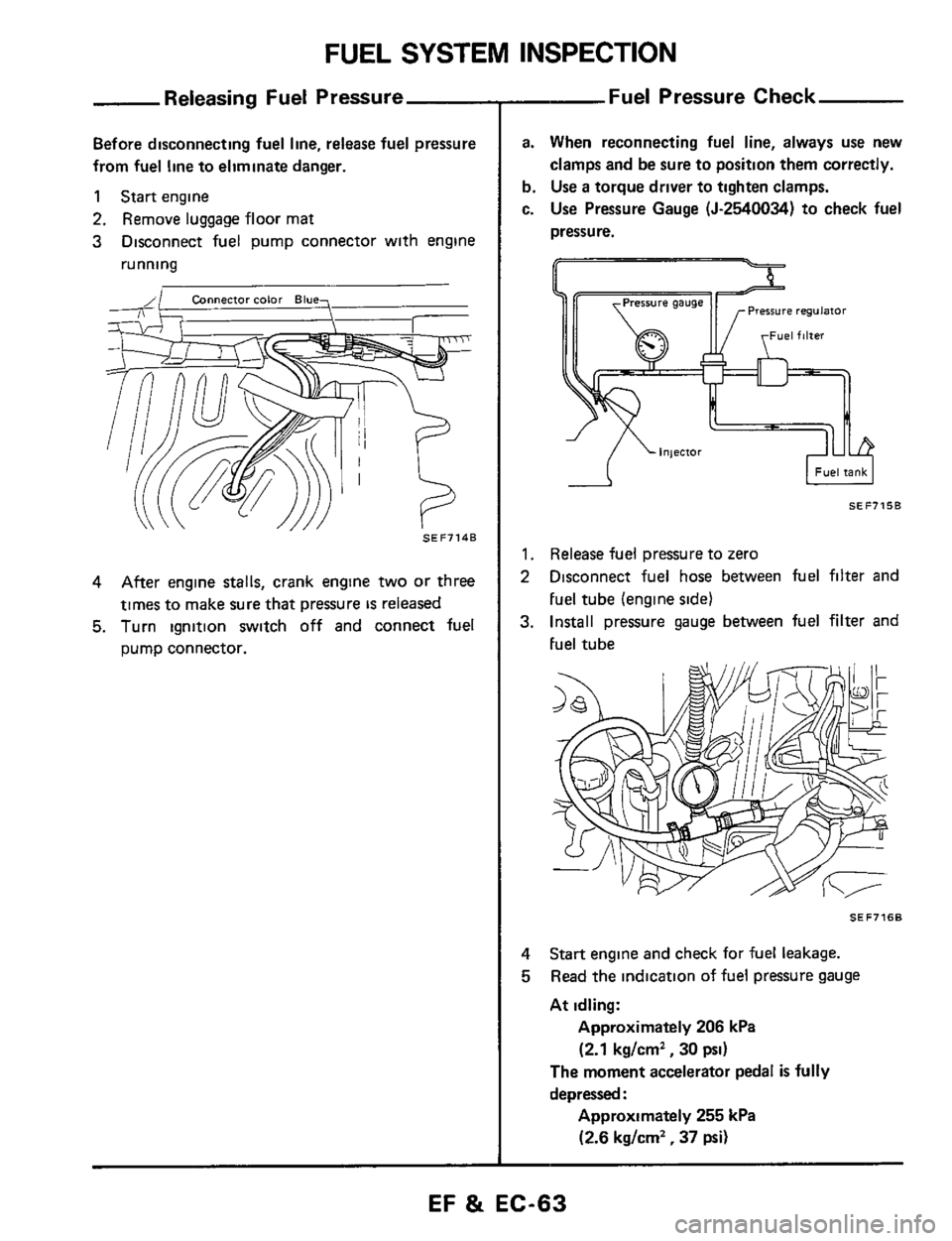
Releasing Fuel Pressure
Before disconnecting fuel line, release fuel pressure
from fuel line to eliminate danger.
1 Start engine
2. Remove luggage floor mat
3 Disconnect fuel pump connector with engine
running
SEF7148
4 After engine stalls, crank engine two or three
times to make sure that pressure
IS released
5. Turn ignition switch off and connect fuel
pump connector.
--Fuel Pressure Check
a. When reconnecting fuel line, always use new
clamps and be sure to position them correctly.
b. Use a torque driver to tighten clamps.
c.
Use Pressure Gauge (5-2540034) to check fuel
pressure.
I Fuel tank I -A
SEF7158
1. Release fuel pressure to zero
2 Disconnect fuel hose between fuel filter and
Fuel tube (engine side1
3. Install pressure gauge between fuel filter and
Fuel tube
SEF7168
4
5
Start engine and check for fuel leakage.
Read the indication of fuel pressure gauge
At idling:
Approximately 206 kPa
(2.1 kg/cm2, 30 psi)
The moment accelerator pedal is fully
depressed
:
Approximately 255 kPa
(2.6 kg/cm2, 37 psi)
EF & EC-63
Page 64 of 79
FUEL SYSTEM INSPECTION
Fuel Pressure Check (Cont'd)
6 Stop engine and disconnect fuel pressure re-
gulator vacuum hose from intake collector
7
Plug intake collector with a rubber cap
8 Connect variable vacuum source (J-23738 or
equivalent) to fuel pressure regulator.
9 Disconnect fuel pump connector and apply
battery voltage
as follows
SEF717B
10 Start engine and read the indication of fuel
pressure gauge as vacuum is changed
Vacuum Fuel prerrure
SEF718B
Vacuum Fuel pressure
kPa (mmHg, inHg) kPa (kg/cm2, psi1
0 (0.01 248 1 .255 0
(2 53
- 2 60.36 0.37 01
227 5.241 3
(2 32.2 46,330.35
01 16 9 (127, 5 00)
213 8.220 7
(2 18.2 25,31 0 - 32 01 33 9 (254. 10 001
200 1 - 206 9
(2 04
- 2 11.29 0- 30 01 50 8 (381,15 00)
179 5. 193 2
(1 83-197.260-280) 67 7 (508.20 00)
Fuel pressure should decrease as vacuum increases.
If results are unsatisfactory, replace fuel pressure
regulator.
EF 8t EC-64
Page 79 of 79

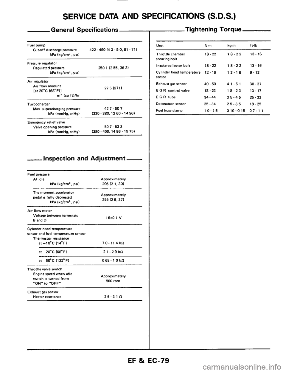
SERVICE DATA AND SPECIFICATIONS (S.D.S.)
General Specifications
Fuel pump Cut-off discharge pressure 422 -490 I4 3 -5 0.61 .71)
kPa (kg/cm'. psi1
Pressure regulator Regulated pressure 250 1 (2 55.36 3) kPa Ikalcm'. Dsll
Air regulatoi
27 5 (971 I Air flow amount
[atZO'C (68OF)I m3 (cu ft)/hr ~~
Turbocharger
Max supercharging pressure 42 7 - 507
kPa (mmHa.
InHal (320-380.1260-1496)
Emergency relief valve Valve opening pressure 507 - 53 3
(380 -400.14 96 - 15 75) kPa (mmHg, InHg)
-inspection and Adjustment -
Fuel pressure
At idle Approximately
kPa (kg/cm', psi) 206 (2 1.30)
The moment accelerator
pedal IS fully depressed Approximately
255 (2 6.371 kPa (kglcm'. psi)
Air flow meter
Voltage between terminals
B and D 1 620 1 V
Cylinder head temperature
sensor and fuel temperature sensor Thermistor resistance
at-lO'C 114'F) 7 0- 11 4 kSl
at 20'C I68'Fl 21-29kSl
at 50°C Il22'FI 068- 1 0 kSl ~~~~
Throttle
valve switch Engine speed when idle
swmh
IS turned from
"ON" to "OFF"
Approximately
900 rpm
Exhaust gas sensor Heater resistance 26-31Sl
- Tightening Torque
-
U"lt Nm kwn ft-lb
Throttle chamber 18-22 18-22 13-16 securing bolt
Intakecollector bolt
18-22 18-22 13-16
Cylinder head temperature 12. 16 1 2.1 6 9.12 SeIlSOr
Exhaust gar senior 40.50 41-51 30-37
E G R control valve 18-23 18-23 13-17
E G H tube 34-44 35-45 25-33
Detonation sensor 25.34 25-35 18-25
Fuel hose clamp 10-15 010-015 07-1 1
EF %i EC-79