Page 11 of 77
BODYENDANDDOOR
Front Door (Cont'd)
POWER WINDOWIWI RING DrAGRAM
(White)
HARNESS POWER WINOOW SUB SWITCH IAssistI --Ass161 MAIN HARNESS LIY-
BATTERY (Via fusible link1
POWER WINDOW
MOTOR IAssirtl
LIY
POWER WINDOW
MOTOR IDriverI
(Driver) LN -
IGNITION SWITCH
ON or START
IGNITION RELAY
w CIRCUIT BREAKER
lured together with power seat1
To engine room harness (Ground)
HARNESS DOOR HARNESS
SBF408B
power door lock actuator POWER DOOR LOCK/WIRING DIAGRAM
FUSE BLOCK
u
I
I L
To engme room - harness IGroundl
.
Power door lock switch
MAIN DOOR HARNESS HARNESS -Driver
SBF409B
BF-I 1
Page 53 of 77
t IGNITION SWITCH I ON or START
IGNITION RELAY 35M
Big;
(For power window and
CIRCUIT
BREAKER
power seat)
To engine room harness L (Ground1
!
t B
,,-CIRCUIT BREAKER
M [ I
r CIRCUIT BREAKER SEAT SWITCH ~~ (Seat Ilfter. sllde. reclining and
thigh support1
Seat cushion ground
- CIRCUIT BREAKER
in harness
LD m ll W (D W m
SEAT BACK SWITCH
RTR AIR PUMP MOTOR
Seat cushion ground
IRiI
CIRCUIT BREAKER Seat curhian ground -
Page 57 of 77
SEAT BELT
Refer to MA section for installation of seat belts.
GLL model has been equipped with seat belts with tension reducer This unit reduces the force required
to pull out seat belt while in use, and lessens pressure on the shoulder and hips for greater comfort
TENSION REDUCER WIRING DIAGRAM
IGNITION SWITCH I ON or ST
TENSION REDUCER-Assist
FUSE BLOCK
@
U
SEAT BELT SWITCH-Assist Iinrjde retractor1 (Main harness1
TENSION REDUCER-Driver (Inside retractor)
SEAT BELT SWITCH-Drwer IM~I~ IPower
harness1 To rime control unit (Seat belt warning lamp1
To engine room harness (Ground)
__ seat cushion ground
TENSION REDUCE OPERATION
SBF439B
Fully Seat belt stroke Fully retraned pulled out SBFMOE
Page 71 of 77

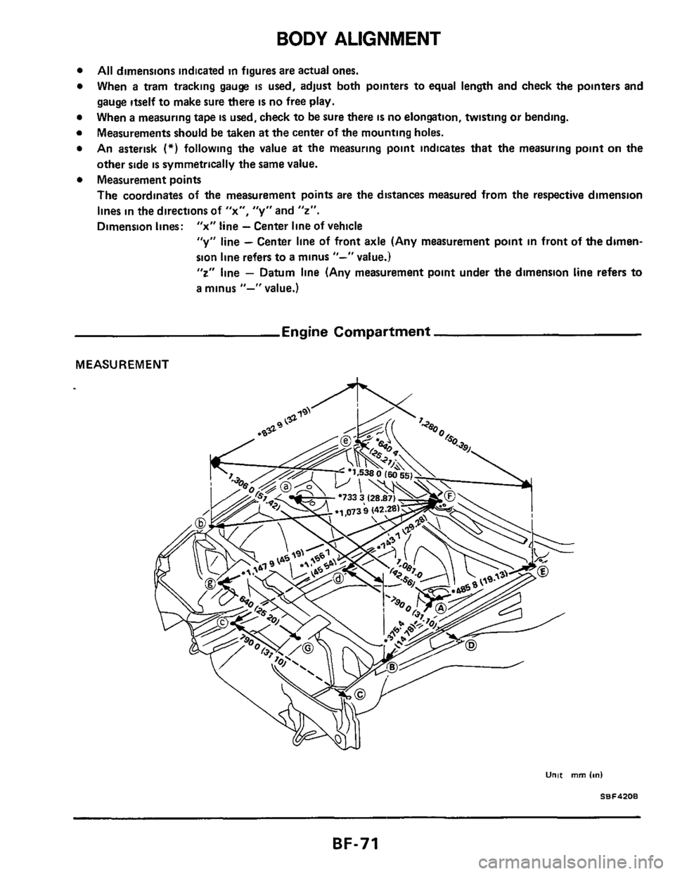
BODY ALIGNMENT
All dimensions indicated in figures are actual ones.
When
a tram tracking gauge is used, adjust both pointers to equal length and check the pointers and
gauge itself to make sure there
is no free play.
When
a measuring tape IS used, check to be sure there IS no elongation, twisting or bending.
Measurements should be taken
at the center of the mounting holes.
An asterisk
(*) following the value at the measuring point indicates that the measuring point on the
other side
is symmetrically the same value.
Measurement points
The coordinates of
the measurement points are the distances measured from the respective dimension
lines in the directions of
"x", "y" and "2".
Dimension lines: "x" line - Center line of vehicle
"y" line - Center line of front axle (Any measurement point in front of the dimen-
sion line refers to
a minus "-" value.)
"2" line - Datum line (Any measurement point under the dimension line refers to
a minus "-" value.)
Engine Compartment
MEASUREMENT
____
BF-71
Page 72 of 77
BODY ALIGNMENT
Engine Compartment (Cont’d)
MEASUREMENT POINTS
Points Hole dia
mm (in) Detailed points Coordinates mm (in)
“X” I, I, 2
540 5
(21 28) -
653 0
(2571)
26 a
(1 0551 -
-325 0
1-12 ao)
Hole for front suspension upper mounting (Outside front
hole) 919 0
(36 1 a)
852 0
(33 54)
490 0
(1 9 29)
490 0
(19 29)
966 0
(38 03)
12 (047)
9 (0 35)
5 4 (0 213)
a (0 31 )
IH
bumper rubber
SBF421B
Hole for fixing front
fender
Hole for fixing har-
ness clip
at upperside
of front side member 395 0
(15 55)
460 0
:-1811l
strut tower
Hole for fixing har-
ness clip
at upperside
of front side member 395 0
(15 55)
100 0
(3 941
Front ride member 1 SBFd23B
Hole for mounting
hood hinge 640 0
(25 20)
500 0
(19 69) 11 (043)
SB F 4248
BF-72
Page 73 of 77
BODY ALIGNMENT
Engine Compartment (Cont'd)
Points Hole dia
mm (in1
7 (0 281
16 (0 631
Detailed points
FR 5BF425E
r Hood bumDer
Hole for mounting
wiper pivot
Hole for mounting
hood bumper rubber
on headlamp side
housing
Coordinates mm (in1 -
"X"
00
(01
320 0
(1 2 60)
-
"Y"
520 8
(20 501
-566 1
(-22 291
"2"
959 0
(37 761
BF-73