Page 38 of 77
BODY END AND DOOR
Theft Warning System (Cont’d)
Alarm mmtnusr (8s not intamittent) - Alarm phase IOperatlon cham step @ 1
Ignition witch OFF
Alarmphase
-
Disconnect main harness connector at
sub-control AMP
YES IAt least one of them)
1
Ched alarm errnit Connect battery ground cable to see
If horn rounds and headlampi light
NO
(Both of them) Faulty theft warning relay - 1
Faulty sub-control AMP
Faulty main control AMP
Faulty adapter harness
BF-38
Page 39 of 77
BODY END AND DOOR
Theft Warning System (Cont'd)
ST- @
8 Ignition switch ST
Check to see of alarm has not been set to
auto-stop phase
Doer alarm restart d any door IS opened?
Disconnect main harness connector at
sukontrol AMP
I v
. Can stamer motor operate when batten'
Check naner motor circuit.
ground cable
IS connected?
1 YES 0 Starter motor malfunction
I
Faulty ruhontrol AMP
Faulty main control AMP
Faulty adapter harness
Faulty starter motor circuit
Faulty theft warning relay - 2
ST- 0
Starter motor can operate - Alarm phase (Operation chart step
Alarm Phase
1 11 Ignitiiswtch ST 1
Check mmr motor clrwlt Wnh battery ground cable connected
and
@ (at main harness side) ( grounded. canoperate check , to see NO If starter motor )?
Faulty starter motor circuit Faulty theft warning relay -2 I 1 I I
Faulty main control AMP
Faulty adapter harness
Faultv harness around
BF-39
Page 40 of 77

m n
0 b
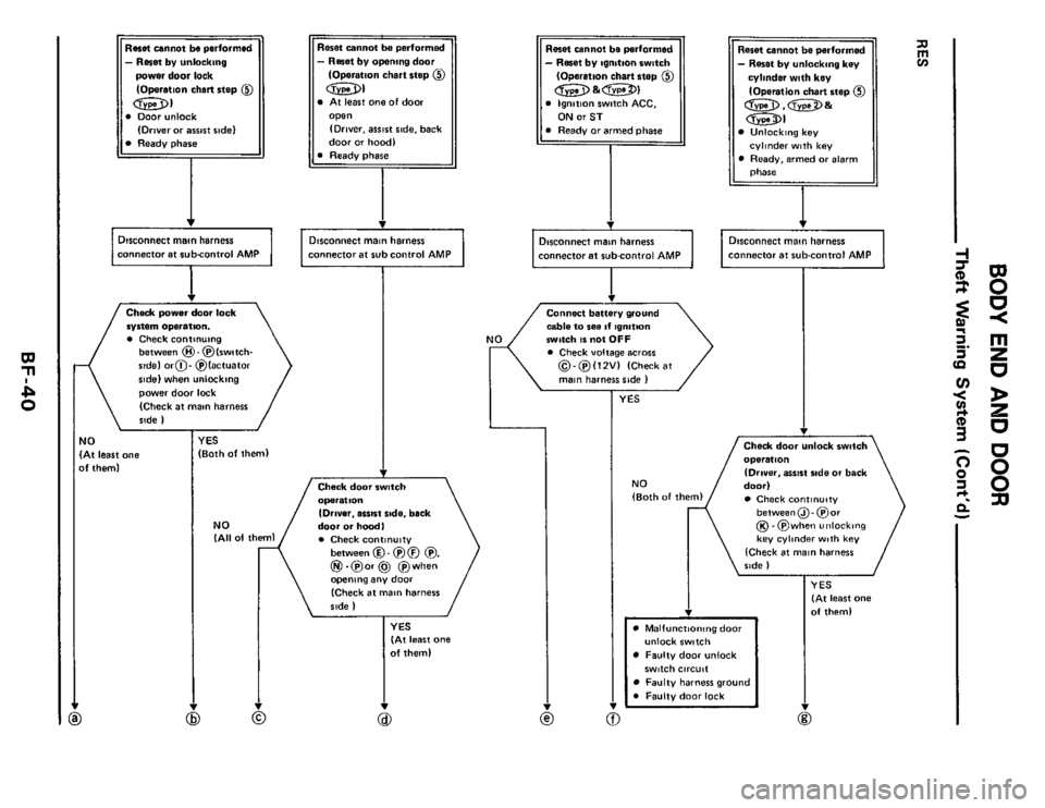
- Reset by unlocking
power door lock
(Operation
chin step @
0 Doorunlock
Ready phase (Driver or awst ridel
Disconnect main harness
Check power door lock
system Operation.
0 Check continuing between @-@(switch-
sidel or@- @lactuator
sidel when unlocking
power door lock
(Check
at main harness
side
I
4t least one
f them)
(Both of theml
- Reset by opening door
(Operation chart step @
At least one of door
IDriver. assrst side. back
door
or hoodl
connector at sub control AMP
r
(Driver. essisl ride. back
door or hoodl
. Check continuity (All of theml
between @ - @ @ @,
@!.@or@ @when
opening any door
(Check at main harness
Reset cannot be performed
- Reset by ignition switch
(Operation chart step @
Ignition switch ACC,
Ready or armed phase
connector at subcontrol AMP
cable to see If ignition
match IS not OFF Cheek voltage BC~OIE
0- @(12Vl (Check at
main harness side I
1
n
v) rn - Reset by unlockan9 key
cylinder with key
(Operation chart step @
Unlocking key
Ready. armed or alarm
cylinder with key
I
Disconnect main harness
I connector at sub-control AMP
+
Check door unlock switch
operattlo"
(Drover, BIIISI ride or back
door1
Check continuity
between@- @or @.@when unlocking
key cylinder with key
(Check at main harness
ride I
YES (At least one
of them1
Malfunctioningdoar
Faulty door unlock
Faulty harness ground
n 0 Faulty door lock
unlock switch
switch circuit
Page 41 of 77
9 8
I I
1
door lock system
Faulty door switch Faulty door switch circuit
Fwlty door switch ground Faulty harness ground
Faulty door alignment
Faulty ignition swltch U Faulty ignition circuit
I
Ready & armed
phase
Alarm phase
Faulty sub-control AMP
Faulty main control AMP U Faulty adapter harness
I
I v
Refer to Trouble-
shootins
"Starter motor cannot
operate
- Except alarm
(Operation chart step
T)i)0@landm)
phase"
Page 42 of 77

BODYENDANDDOOR
Theft Warning System (Cont'd)
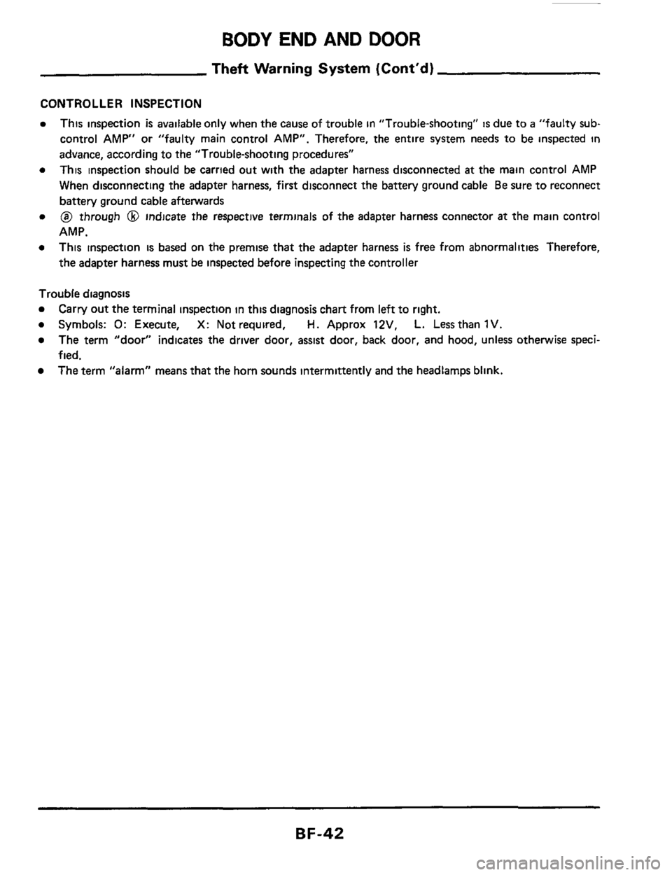
CONTROLLER INSPECTION
This inspection is available only when the cause of trouble in "Troubleshooting" is due to a "faulty sub-
control
AMP" or "faulty main control AMP". Therefore, the entire system needs to be inspected in
advance, according to the "Trouble-shooting procedures"
This inspection should be carried out with the adapter harness disconnected
at the main control AMP
When disconnecting the adapter harness, first disconnect the battery ground cable Be sure to reconnect
battery ground cable afterwards
@I through 0 indicate the respective terminals of the adapter harness connector at the main control
AMP.
This inspection
is based on the premise that the adapter harness is free from abnormalities Therefore,
the adapter harness must be inspected before inspecting the controller
Trouble diagnosis
b Symbols: 0: Execute, X: Not required, H. Approx 12V, L. Lessthan 1V.
Carry out the terminal inspection in this diagnosis chart from left to right.
The term "door" indicates the driver door, assist door, back door, and hood, unless otherwise speci-
fied.
The term "alarm" means that the horn sounds intermittently and the headlamps blink.
BF-42
Page 46 of 77
m n
i?. Q, ~
ST-@
I Trouble
condition Trouble-
shooting
Starter motor cen operate
-Alarm phese
(Operation chan step 01
Ignition switch ST
Alarm phase
No I
Starter motor annot owrate
-Exapt alarm phase
Ignition swttch ST
RW cennot ba performed RES
ower source
terminal
inspction
H
H
H
*11 When door IS closed-Dirarmed phase and reset phase *12 When door is opened or ready phase '13 After closing Ea locking door, Walt over 40 seconds and then measure '14 When door IS opened '15 When power door lock system unlocks
*16 Ignition switch ACC, ON or ST
Ground
terminal
inspection Output terminal
inspection
q
0 000
Input terminal inswctton
-
0 - H
e11
L '12 -
H
'13
-
L
'14 -
H '15 *16
Result
OK
(All of
them)
NG
(At
least one of them)