Page 265 of 394
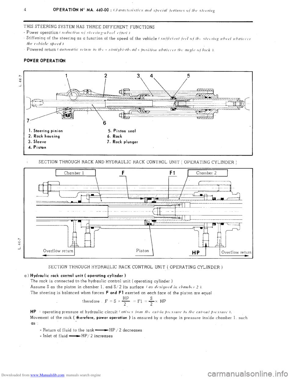
Downloaded from www.Manualslib.com manuals search engine THIS STEERING SYSTEM HAS THREE DIFFERENT FUNCTIONS
- Power operation i rc,d/ic-/ici// 0 I .~/I c,r-i/lg-o /Io.c,/ c’//or/ /
Stiffeninq of the steerinq as a function of the speed of the vehicle f s////it-ic,r/t /<,(,I o/ 11~1 c/c,c~ri/t.cq r/~llc(,I I//JNI(,I or
lhc, 1 cjhicle spc,c~d )
1. Steering pinion 5. Piston seal
2. Rack housing 6. Rack
3. Sleeve 7. Rack plunger
4. Piston
I SECTION THROUGH RACK AND HYDRAULIC RACK CONTROL UNIT ( OPERATING CYLINDER )
SECTION THROUGH HYDRAULIC RACK CONTROL UNIT ( OPERATING CYLINDER )
a) Hydraulic rack control unit ( operating cylinder )
The rack is connected to the hydraulic control unit ( operating cylinder )
Assume S as the piston in chamber 1, and S/ 2
its surface ( ns dcjsiguvd iu c-hmvhc 1’ 2 J.
The steering is balanced when forces F and Fl exerted on each face of the piston are equal
therefore F = S x F =Fl +x HP
HP 1 operatinq pressure of hydraulic circuit f mist s l‘ront /hc r-r/-iit /I,,( s.5~1’~~ lo fhc cf4I-r)ul /~r~~.~.s~ir~~ J.
Movement of the rack ( therefore, power operation ) is ensured by a change in pressure inside chamber 1, such
as
I Return of fluid to the tank -HP / 2 decreases
- Inlet of fluid -HP/ 2 increases
Page 266 of 394
Downloaded from www.Manualslib.com manuals search engine b) Control unit : ’
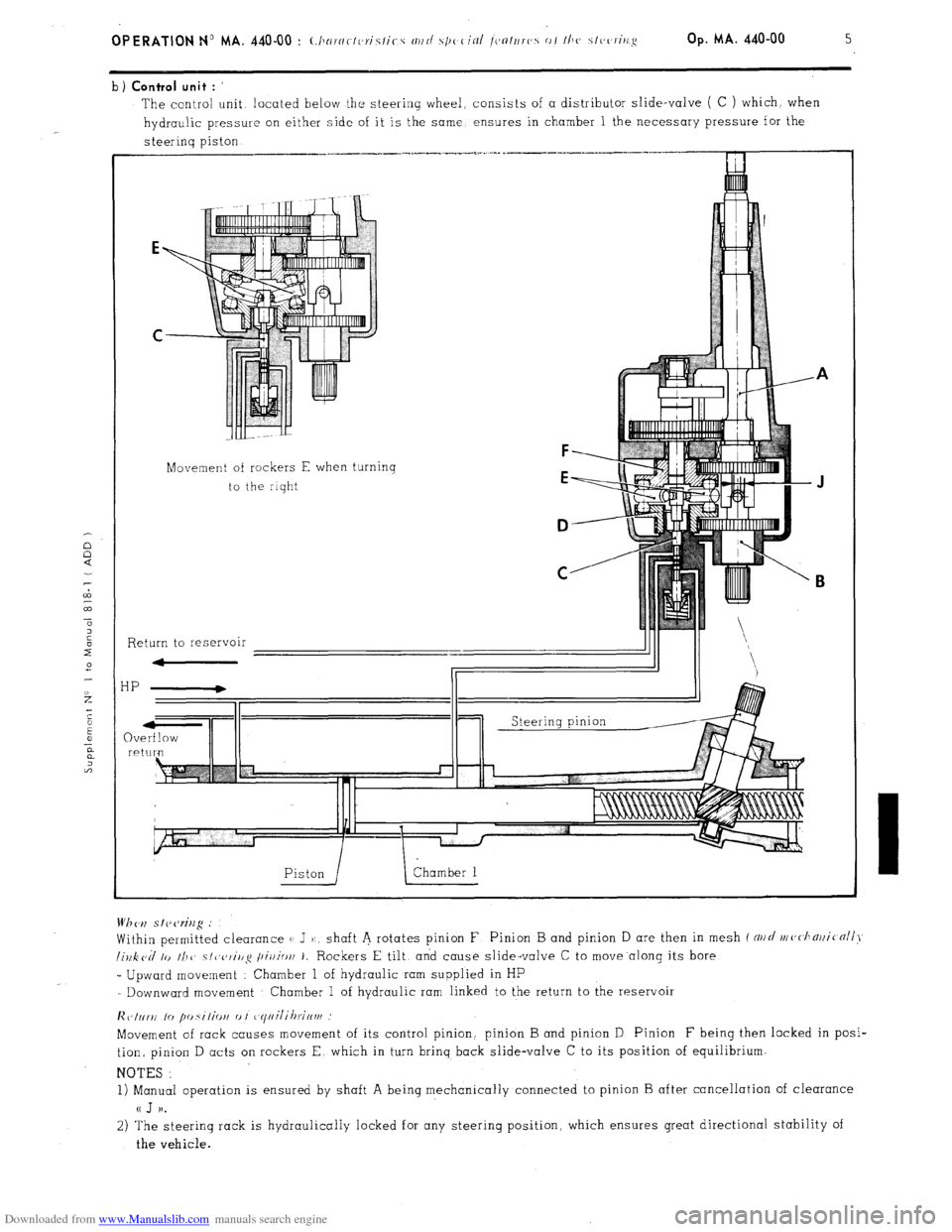
The contra! unit located below the steering wheel, consists of a distributor slide-valve ( C ) which. when
hydraulic pressure on either side of it is the same ensures in chamber 1 the necessary pressure for the
steerinq piston
Movement of rockers E when turning
to the riqht
F
E
D
C
Return to reservoir
HP
QV re Wh <‘,I s I? cw%g .’
Within permitted clearance (1 J ):, shaft A rotates pinion F Pinion B and pinion D are then in mesh f NII~/ nl(,<.l1~)ji(nll>~
lillk cd lo II1 1’ ~/~~c,~i/lg /~ir/io/l 1. Rockers E tilt, and cause slide-valve C to move.along its bore
_ Upward movement : Chamber 1 of hydraulic ram supplied in HP
- Downward movement Chamber 1 of hydraulic ram linked to the return to the reservoir
lic,Inr~i lo fm.silio~i 0 I ~~yiiilihrif~vf
Movement of rack causes movement of its control pinion. pinion B and pinion D Pinion F being then locked in posi-
tion, pinion D acts on rockers E. which in turn brinq back slide-valve C to its position of equilibrium.
NOTES :
1) Manual operation is ensured by shaft A being mechanically connected to pinion B after cancellation of clearance
a J )).
2) The steering rack is hydraulically locked for any steering position, which ensures great directional stability of
the vehicle.
Page 267 of 394
Downloaded from www.Manualslib.com manuals search engine 6
OPERATION No MA. 440-00 : (.hnrcrc-tcrislics nrtd .s/)oc-in/ /c~n/trr(~s o/ I/I(~ .s/(,(zri,~g
VARIATION OF FEEL as a function of the speed of the vehicle
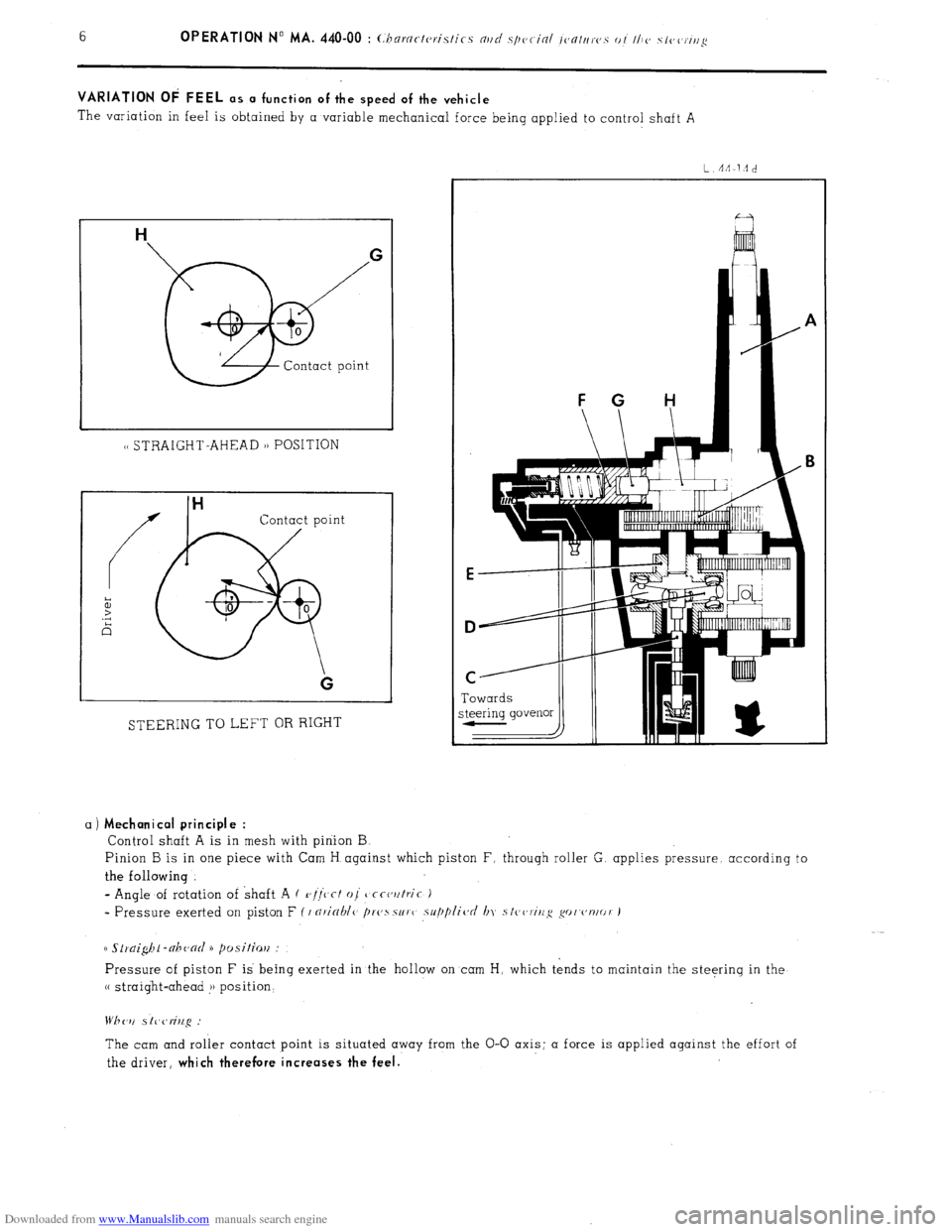
The variation in feel is obtained by a variable mechanical force being applied to control shaft A
1~ STRAIGHT-AHEAD 1) POSITION
Contact point
STEERING TO LEFT OR RIGHT Towards
a)
Mechanical principle :
Control shaft A is in mesh with pinion B
Pinion B is in one piece with Cam H against which piston F, through roller G. applies pressure. according to
the following
- Angle of rotation of shaft A ( r,//‘c’cf oj
tjcct,utric )
* Pressure exerted on piston F ( I nricrhlc> /)r(,ssur( supplic~d In stc,~,ririg go('~'nlor J
Pressure of piston F is being exerted in the hollow on cam H, which tends to maintain the steering in the
(( straight-ahead !j position‘
The cam and roller contact point is situated away from the O-O axis; a force is applied against the effort of
the driver,
which therefore increases the feel.
Page 268 of 394
Downloaded from www.Manualslib.com manuals search engine d
m
.-
0
2
f Op. MA. 440-00
7 -
b) Steering governor :
It is situated on the front subframe, and mechanically driven ( cable ) by the final drive unit in the gearbox.
Ei A ”
VEHICLE STOPPED (engine running)
L.44-14b
I/ /II I Pressure
IL Towards
HP cam cylinder
VEHICLE IN MOTION
* Slide-valve A is linked in linear motion to lever B
- Fly-weights C, which rotate ( and fly towards under the effect of centrifugal force ) cause lever B to tilt.
=
L'nrioblc, position of slide-valve A, allows the pressure exerted on the cam cylinder piston to be varied.
NOTE In order to make possible the powered return function. the steerinq governor supplies a pressure
of 20 i-15 bars ( 290 +173 psi ) when the vehicle is stopped f 11
i/F /hc cwgir/e wt/t~iv.g i.
I
POWERED RETURN
The powered return is a combination of the two preceding functions, the variable feel function controlling the
power-operation function.
Page 269 of 394
Downloaded from www.Manualslib.com manuals search engine a ) Mechanical principle
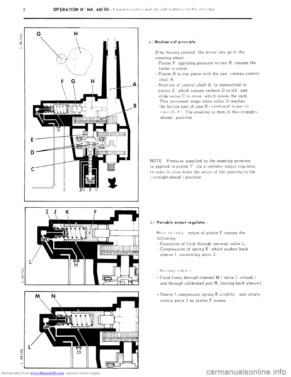
After having steered the driver lets go of the
s teerinq wheel
Piston F applyinq pressure to cam H, causes the
latter to rotate.
- Pinion B in one piece with the cam rotates control
shaft A.
- Rotation of control shaft A, is transmitted to
pinion E which causes rockers D to tilt and
slidecvalve C to move which moves the rack.
This movement stops when roller G reaches
the hollow part of cam H ( ro/~/i<,//~/ /or(//((’ is
(-(II/( V/I< N’ ) The steerinq is then in the c
ahead i) position.
NOTE Pressure supplied by the steering governor
is applied to piston F via a variable output requlator
in order to slow down the return of the steerinq to the
v straiqht-ahead a) position.
b)
Variable output regulator :
Wh(‘I/ \I< criq .’ return of piston F causes the
following
_ Expulsion of fluid through one-way valve L
= Compression of sprinq K. which pushes back
sleeve I uncovering ports J.
(1 . I vl,riil,q rc l//rI/ D
- Fluid flows throuqh channel M ( valve L closed )
and through calibrated port N, forcing back sleeve I.
= Sleeve I compresses sprinq K sliqhtly and slowly
covers ports J as piston F moves.
Page 270 of 394
Downloaded from www.Manualslib.com manuals search engine CROSS-SECTION OF CONTROL UNIT
L. 14-3 n
In
Page 271 of 394
Downloaded from www.Manualslib.com manuals search engine 10 OPERATION No MA. 440-00 : (:hnrnct(,rictic.,s nttd .s/)cjcitil jcntr/rc,.s 01 the stc,c,rirtg CROSS-SECTION OF STEERING GOVERNOR
L.
44-16
Page 272 of 394
Downloaded from www.Manualslib.com manuals search engine Op. MA. 440.00 11
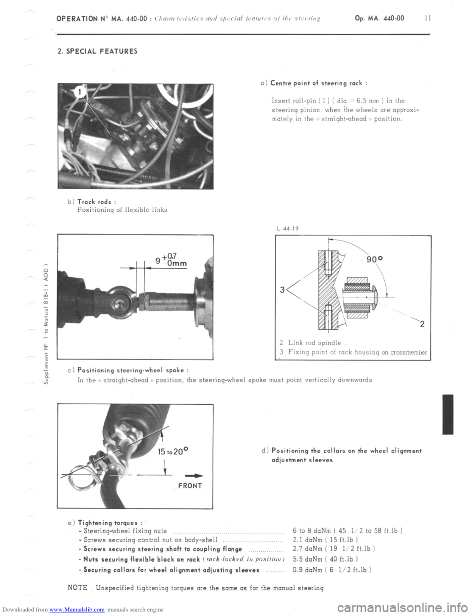
2. SPECIAL FEATURES
a) Centre point of steering rack :
Insert roll-pin ( 1 ) ( dio -: 6.5 mm ) in the
steering pinion when ihe wheels are appraxi-
mutely in the GG siroightohead )B position.
b 1 Track rods :
Positioning of flexible links
4J
a c) Positioning steering-wheel spoke :
2 Link rod spindle
3 Fixing point of rock housing on crossmemker
In the C( straight-ahead )) position, the steering-wheel spoke must point vertically
downwards
d) Positioning the collars on the wheel alignment
adjustment sleeves ---
FRONT
e) Tightening torques :
- Steering-wheel fixing nuts ..,.,........,......,.. .., 6 to 8 daNm ( 45 li 2 to 58 ft.lb j
- Screws securing control nut on body-shell 2.1 daNm ( 15 ft.lb )
. Screws securing steering shaft to coupling flange ,.,,.,,,,,.,.,.,,, 2.7 doNm ( 19 li2 ft.lb )
- Nuts securing flexible block on rack C rnrh lorkc~d iu psi/h) 5.5 doNm ( 40 ft.lb )
-Securing collars for wheel olignmani adjusting sleeves 0.9 daNm ( 6 l/2 ft.lb )
NOTE Unspecified tightening torques are the same as for the manual steering