1982 VOLVO 960 belt
[x] Cancel search: beltPage 12 of 168
70019401960 Specifications
Section
0 General
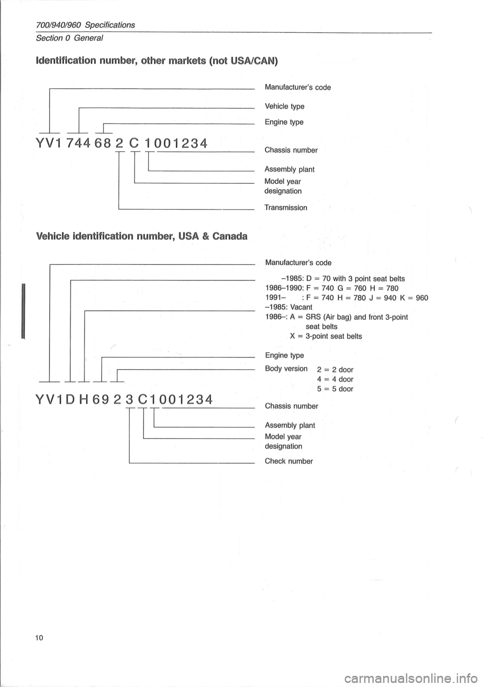
Identification number, other markets (not USA/CAN )
l~ L
YV1 74468 2 C 1 001234
TTL----
Vehicle identification number, USA & Canada
YV1DH6923C1001234
11"--------
10
Manufacturer's code
Vehicle type
Engine type
Chassis number
Assembly plant
Model
year
designation
Transmission
Mc; mufacturer's code
-1985: D = 70 with 3 poi nt seat belts
1986-1990: F = 740 G = 760 H = 780
1991-: F = 740 H = 780 J = 940 K = 960
-1985: Vacant
1986-: A = SRS (Air bag) and front 3-point
seat
belts
X = 3 -point seat belts
Engine type
Body version 2
= 2 door
4
= 4 door
5 = 5 door
Chassis number
Assembly plant
Model
year
designation
Check number
(
Page 34 of 168
70019401960 Specifications
Section 2 B 19, B 23 Engines
General
Group 26 Cooling system
128187
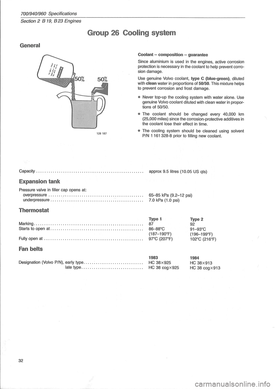
Coolant - composit ion -guarantee
Since aluminium is used in the engines, active corrosion
protection
is necessary in the coolant to help prevent corro
sion damage.
Use genuine
Volvo coolant, type C (blu e-green), diluted
with clea n water in proportions of SO/50. This mixture helps
to prevent corrosion and frost damage.
• Never top-up the cooling system with water alone. Use
genuine
Volvo coolant diluted with clean water in propor
tions of 50/50.
•
The coolant should be changed every 40,000 km
(25,000 miles) since the corrosion-protective additives in
the coolant lose their effect in time.
• The cooling system should be cleaned using solvent
PIN 1 161 328-8 prior to filling new coolant.
Capacity . . . . . . . . . . . . . . . . . . . . . . . . . . . . . . . . . . . . . . . . . . . . . . . . . . . . approx 9.5 litres (10.05 US qts)
Expans ion tank
Pressure valve in filler cap opens at:
overpressure
........ ' ..................................... .
underpressure .
.............................. --: ............ .
Thermostat
Marking .................................................... .
Starts to open
at ............................................ .
Fully open at ...................................... ......... .
Fan belts
Designation (Volvo PIN), early type ..... : ...................... .
late type ............................. .
32
65-85 kPa (9.2-12 psi)
7.0 kPa (1.0 psi)
Type 1
87
86-88°C
(187-190°F)
9rC (207°F)
1983
HC 38x925
HC 38 cogX925
Type 2
92
91-93°C
( 196-199°F)
102°C (216°F)
1984
HC 38x913
HC 38 cogX913
Page 42 of 168
70019401960 Specifications
Section 2 B 200, B 230 Engines
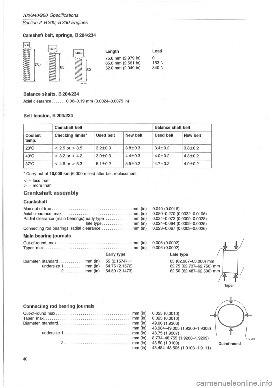
Camshaft belt, sp ring s, B 204/234
144B!Hi
Balanc e shaf ts , B 204 /234
Length
75.6 mm (2.979 in)
65.0 mm (2.561 in)
52.0 mm (2.049 in)
Axial clearance. . . . .. 0.06-0.19 mm (0.0024-0.0075 in)
Belt tension, B 204/ 234
Camshaft belt
Coolant
Checking limits ' Used belt New belt
temp.
20°C < 2 .5 or > 3.5 3.2±0.3 3.8±0.3
40°C < 3.2 or > 4.2 3.9±0.3 4.4±0.3
8rC < 4.6 or > 5.3 5
.1 ±0.2 5 .5±0.2
• Carry out at 10,000 km (6,000 miles) after belt replacement.
< = less than
> = more than
Crankshaft assembly ,/
Cranksh aft
Max out-at -true .................................. ..... mm (in)
Axial clearance, max .................................. mm (in)
Radial clearance (main bearings) early type ............. mm (in)
late type ............... mm (in)
Connecting rod bearings, radial clearance ............... mm (in)
Main bearing journals
Out-at-round , max ................................ .... mm (in)
Taper, max
........................................... mm (in)
Early type
Diameter , standard ............. mm (in) 55 (2.1574)
54.75 (2.1572)
54.50 (2. 1473)
undersize
1
.......... mm (in)
2 .......... mm (in)
Connecting rod bearing journa ls
Out-at-round max ..................................... mm (in)
Taper, max .
.......................................... mm (in)
Diameter, standard .
............ , ...................... mm (in)
mm (in)
40
undersize 1 ................................. mm (in)
mm (in)
2 ................. ................ mm (in)
mm (in)
Load
o
153 N
340 N
Balance shaft belt
Used belt New belt
3.4±0.2 3.8±0.2
4.0±0.2 4.3±0.2
4.7±0.2 4.9±0.2
0 .040 (0.0016)
0.080-0 .270 (0.0032-0.0106)
0 .
024-0.072 (0.0009--0 .0028)
0.024-0.064 (0.0009--0.0025)
0.023-0.067
(0. 0009--0.0026)
0.006 (0.0002)
0.006 (0.0002)
Late type
63 (62.987-63 .000) mm
62.75 (62.737-62.750) mm
62.50 (62.487-62.500) mm
t
Taper
0.025(0.0010) f ~
0.025 (0.0010) ) 49.00 (1.9306)
48.984-49.005
(1.9300-1.9308)
48.75 (1.9207)
8.734-48.755 (1.9208-1.9209)
115 089
48.50 (1.9109) Out-ot-round
48.484-48.505 (1.9103-1.9111)
Page 85 of 168
(
General
70019401960 Specifications
Section
2 B 28 Engine
Group 26 Cooling system
128187
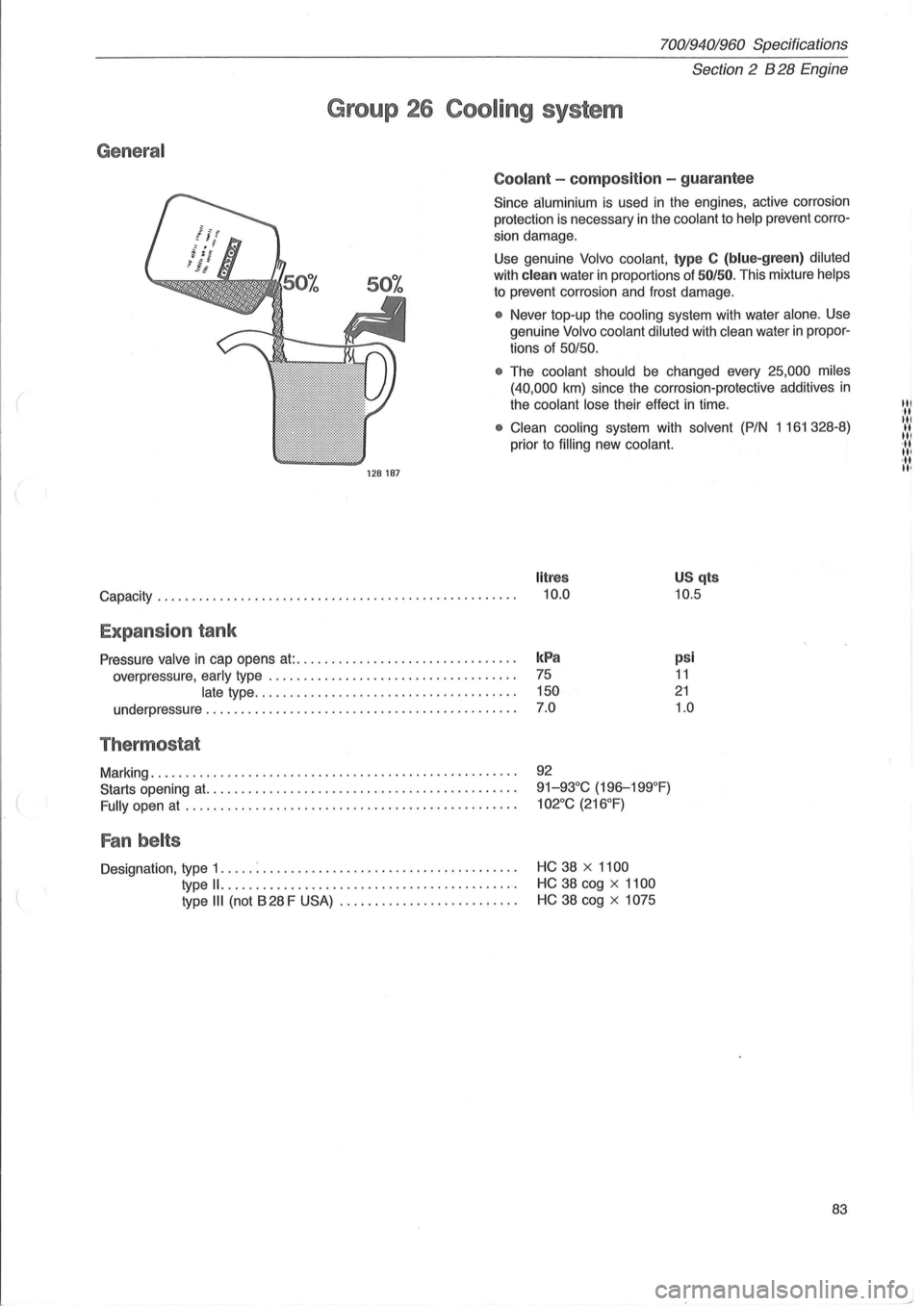
Coolant -composition -guarantee
Since aluminium is used in the engines, active corrosion
protection is necessary
in the coolant to help prevent corro
sion damage .
Use genuine
Volvo coolant, type C (blue-green ) diluted
with clean water in proportions of 50/50. This mixture helps
to prevent corrosion and frost damage.
• Never top-up the cooling system with water alone. Use
genuine
Volvo coolant diluted with clean water in propor
tions of
50/50.
•
The coolant should be changed every 25,000 miles
(40,000
km) since the corrosion-protective additives in
the coolant lose their effect in time.
• Clean cooling system with solvent (P/N 1161328-8)
prior to
filling new coolant.
litres
Capacity. . . . . . . . . . . . . . . . . . . . . . . . . . . . . . . . . . . . . . . . . . . . . . . . . . . . 10.0
US qts
10.5
Expansion tank
Pressure valve in cap opens at:. . . . . . . . . . . . . . . . . . . . . . . . . . . . . . . . kPa
overpressure, early type . . . . . . . . . . . . . . . . . . . . . . . . . . . . . . . . . . . . 75
late type. . . . . . . . . . . . . . . . . . . . . . . . . . . . . . . . . . . . . . 150
underpressure . . . . . . . . . . . . . . . . . . . . . . . . . . . . . . . . . . . . . . . . . . . . .
7.0
Thermostat
Marking .................................................... .
Starts opening
at. ........................................... .
Fully open at ............................................... .
Fan belts
Designation, type 1 ..... : ................................ .... .
type
11. ..................•......•................
type III (not B 28 F USA) ......................... .
92
91-93°C (196-199°F)
102°C (216°F)
HC 38 x 1100
HC 38 cog x 1100
HC 38 cog x 1075
psi
11
21
1.0
83
til ·tt til II III '11 III ·tt II'
Page 98 of 168
70019401960 Specifications
Section
2 B 280 E ngine
General
Group 26 Cooling system
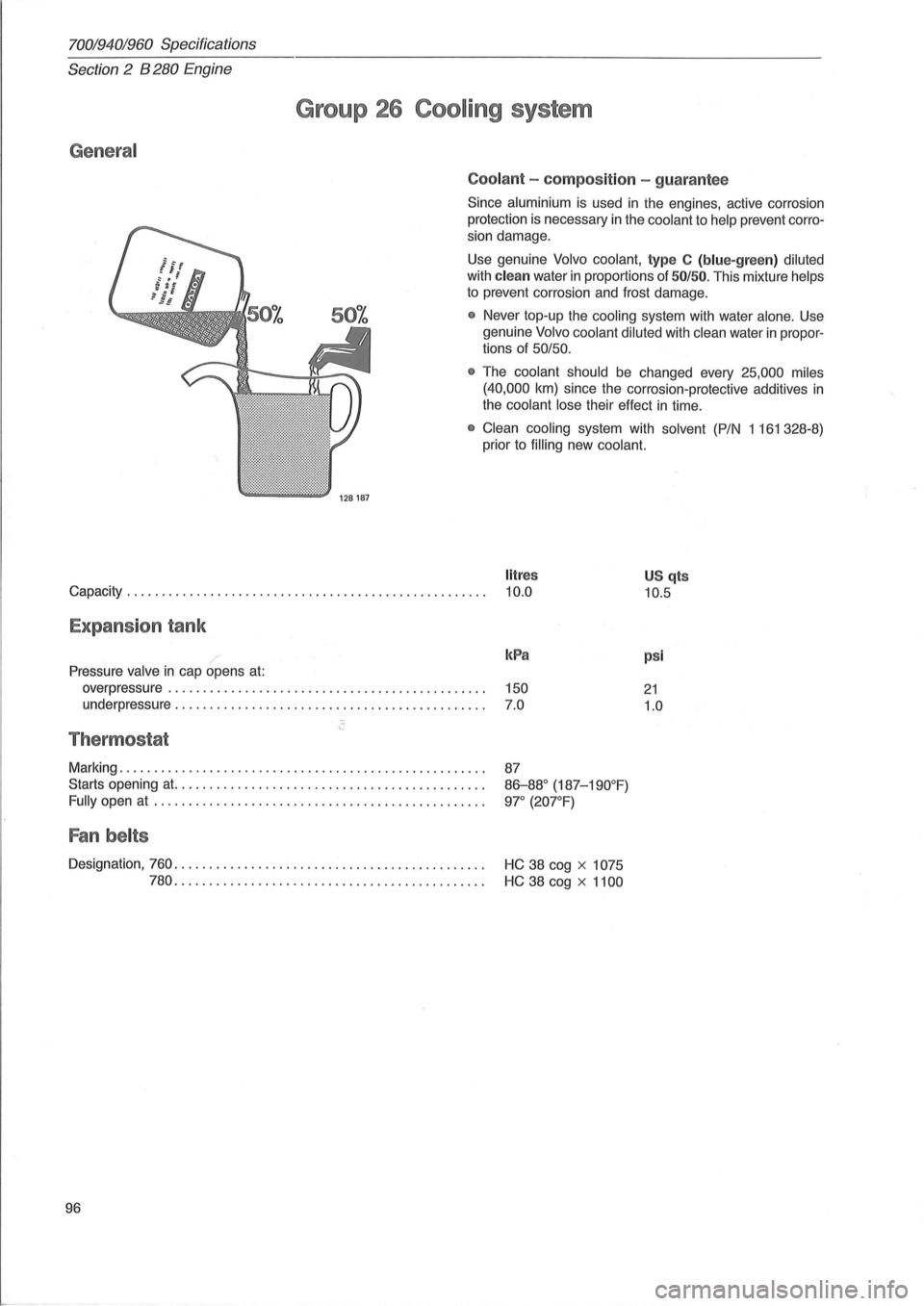
Coolant -compos it ion -gua rantee
Since aluminium is used in ihe engines, active corrosion
protection
is necessary in the coolant to help prevent corro
sion damage.
Use genuine
Volvo coolant, type C (blue-green ) diluted
with clean water in proportions of 50/ 50. This mixture helps
to prevent corrosion and frost damage.
• Never top-up the cooling system with water alone. Use
genuine
Volvo coolant diluted with clean water in propor
tions of
50/50.
•
The coolant should be changed every 25,000 miles
(40,000
km) since the corrosion-protective additives in
the coolant lose their effect in time.
• Clean cooling system with solvent (P/N 1161328-8)
prior to
filling new coolant.
litres
Capacity. . . . . . . . . . . . . . . . . . . . . . . . . . . . . . . . . . . . . . . . . . . . . . . . . . . . 10.0 U S qts
10.5
Expans ion tank
Pressure valve in cap opens at:
overpressure ...................................... .. ..... .
underpressure
............................................ .
Thermostat
Marking .. .................................................. .
Starts opening at. ........................................... .
Fully open at ............................................... .
Fan belts
kPa
150
7.0
87
86-88° (187-190°F)
9l" (20l"F)
Designation, 760. . . . . . . . . . . . . . . . . . . . . . . . . . . . . . . . . . . . . . . . . . . . . HC 38 cog x 1075
780.
. . . . . . . . . . . . . . . . . . . . . . . . . . . . . . . . . . . . . . . . . . . . HC 38 cog x 1100
96
psi
21
1.0
Page 103 of 168
(
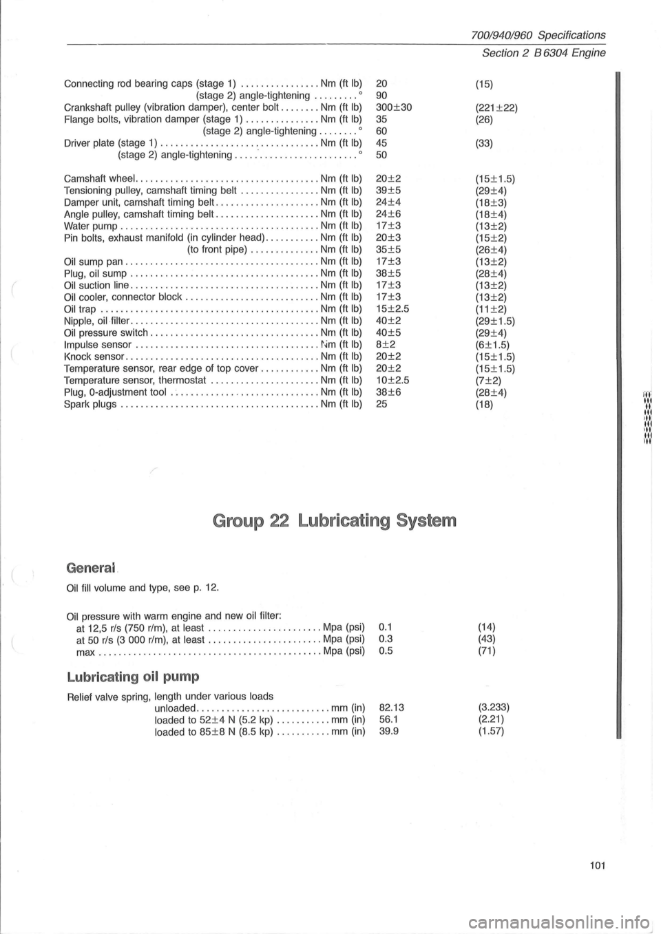
Connecting rod bearing caps (stage 1) ................ Nm (ft Ib)
(stage 2) angle-tightening ......... 0
Crankshaft pulley (vibration damper), center bolt ........ Nm (ft Ib)
Flange bolts, vibration damper (stage 1) ............... Nm (ft Ib)
(stage 2) angle-tightening ........ 0
Driver plate (stage 1) ......................... ....... Nm (ft Ib)
(stage 2) angle-tightening ......................... 0
Camshaft wheel. .................................... Nm (ft Ib)
Tensi oning pulley, camshaft timing belt ................ Nm (ft Ib)
Damper unit, camshaft timing belt ..................... Nm (ft Ib)
Angle pulley, camshaft timing belt ..................... Nm (ft Ib)
Water pump ........................................ Nm (ft Ib)
Pin bolts, exhaust manifold (in cylinder head) ........... Nm (ft Ib)
(to front pipe) .............. Nm (ft Ib)
Oil sump pan ....................................... Nm (ft Ib)
Plug, oil sump ...................................... Nm (ft Ib)
Oil suction line ...................................... Nm (ft Ib)
Oil cooler, connector block ........................... Nm (ft Ib)
Oil trap ............................................ Nm (ft Ib)
Nipple, oil·filter ...................................... Nm (ft Ib)
Oil pressure switch .................................. Nrn (ft Ib)
Impulse sensor ..................................... ~~m (ft Ib)
Knock sensor ....................................... Nm (ft Ib)
Temperature sensor, rear edge of top cover ............ Nm (ft Ib)
Temperature sensor, thermostat ............... ....... Nm (ft Ib)
Plug, O-adjustment tool .............................. Nm (ft Ib)
Spark plugs ... ..................................... Nm (ft Ib)
20
90
300±30
35
60 45
50
20±2
39±5
24±4
24±6
17±3
20±3
35±5
17±3
38±5
17±3
17±3
15±2.5
40±2
40±5
8±2
20±2
20±2
10±2.5
38±6
25
Group 22 Lubricating System
Genera l
Oil fill volume and type, see p. 12.
Oil pressure with warm engine and new oil filter :
at 12,5 rls (750 rim), at least ....... ................ Mpa (psi) 0.1
at
50 rls (3 000 rim), at least ....................... Mpa (psi) 0.3
max
...................... ....................... Mpa (psi) 0.5
Lubricat ing oil pump
Relief valve spring, length under various loads
unloaded
.................... ....... mm (in)
loaded to 52±4 N (5.2 kp) ....... .... mm (in)
loaded to 85±8 N (8.5 kp) ........... mm (in)
82.13
56.1
39.9
70019401960 Specifications
Section 2 B 6304 Engine
(15)
(221 ±22)
(26)
(33)
(15±1.5)
(29±4)
(18±3)
(18±4)
(13±2)
(15±2)
(26±4)
(13±2)
(28±4)
(13±2)
(13±2)
(11 ±2)
(29±1.5)
(29±4)
(6±1.5)
(15±1.5)
(15±1.5)
(7±2)
(28±4)
(18)
(14)
(43)
(71 )
(3.233) (2.21)
(1.57)
101
I ..... ' '.','
"' ,III III ill u,1
Page 113 of 168
(
70019401960 Specifications
Section 2
024, 024 T, 024 TIC Engines
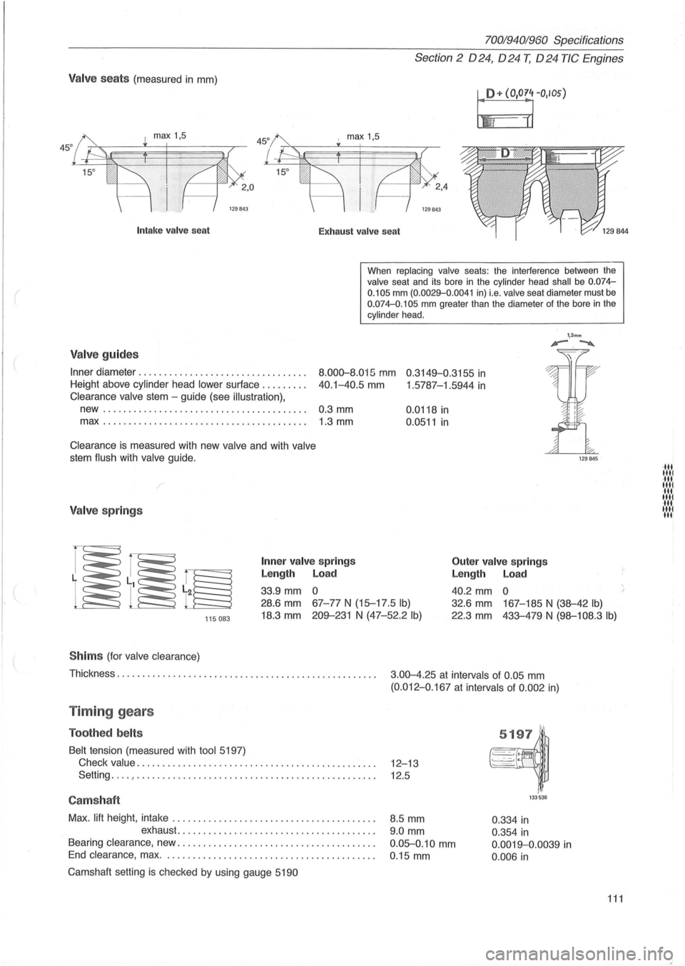
Valve seats (measured in mm)
I!+ (O'O~rIOS)
I max 1,5
129843
Intak e valve sea t
Exhaust valv e seat
When
replacing valve seats: the interference between the valve seat and its bore in the cylinder head shall be 0.074-
0.105 mm (0.0029-0 .0041 in) i.e. valve seat diameter must be 0.074-0.105 mm greater than the diameter of the bore in the cylinder head .
Valve guides
Inner diameter ............... ................. .
Height above cylinder head
lower sur1ace ........ .
8.000-8.015 mm 0 .3149-0.3155 in
40.1-40.5 mm 1 .5787-1.5944 in Clearance valve stem -guide (see illustration),
new........................................ 0.3 mm
max.. ...................................... 1.3 mm
Clearance is measured with new valve and with valve
stem flush with valve guide.
/
Valve springs
Inner va lv e spring s
Length Load
33.9 mm 0 0.0118
in
0.0511 in
Outer
valve springs
Length Load
40.2 mm 0
1,3mm '-.~
115083
28.6 mm 67-77 N (15-17 .5 Ib)
18.3 mm 209-231 N (47-52.2 Ib)
32.6 mm 167-185 N (38-42 Ib)
22.3 mm 433-479N (98-108.3 Ib)
S him s (for valve clearance)
Thickness. . . . . . . . . . . . . . . . . . . . . . . . . . . . . . . . . . . . . . . . . . . . . . . . . . .
3.00-4.25 at intervals of 0.05 mm
(0.012-0 .167 at intervals of 0 .002 in)
Timing gears
Toothed belts
Belt tension (measured with tool 5197)
Check
value. . . . . . . . . . . . . . . . . . . . . . . . . . . . . . . . . . . . . . . . . . . . . . . 12-13
Setting
... . , . . . . . . . . . . . . . . . . . . . . . . . . . . . . . . . . . . . . . . . . . . . . . . . 12.5
Camshaft
Max. lift height , intake ....................................... .
exhaust
...................................... .
Bearing clearance, new .
..................................... .
End clearance , max. . ....................................... .
Camshaft setting
is checked by using gauge 5190
8.5 mm
9.0 mm
0.05-0.10 mm
0 .15 mm
133536
0.334 in
0.354 in
0.0019-0.0039 in
0.006 in
111
·111 1111 ·111 1111 ·111 1111 11 .... 1 III
Page 119 of 168
(
General
024
Capacity: with manual
gearbox ......... litres (US qts) 9.5
(9.9)
with
aut.
gearbox ......... litres (US qts) 9.2
(9.7)
70019401960 Specifications
Section 2 024, 024 T, 024 TIC Engines
Group 26 Cooling system
128187
024T 024TIC
11.0 11.5
(11.6) (12
.
2)
10.0 11.5
(10.6) (12.2)
Coolant
Since aluminium is used in the engines, active corrosion
protection is necessary in the
coolant to help prevent corro
sion damage.
Use genuine Volvo coolant type C (blue-green) diluted
with clean water in proportions of 50/50. This mixture helps
to prevent corrosion and frost damage.
• Never top-up the cooling system with water alone . Use
genuine
Volvo coolant diluted with clean water in propor
tions of 50/50.
•
The coolant should be changed every 25,000 miles
(40,000
km) since the corrosion-protective additives in
the coolant lose their effect in time.
• Clean cooling system with solvent (P/N 1 161 328-8)
prior to
filling new coolant.
• If tropic type radiator is filled add 0.6 (0.6) to above.
Important: do not operate engine if cooling system is not topped-up. Failure to observe this may cause high local temperatures which could cause cylinder head to fracture .
Expansion tank /
Pressure valve in cap opens at:
overpressure, early type ............................ kPa (psi)
late type ............................. kPa (psi)
underpressure
............... ...................... kPa (psi)
Thermostat
Marking ..................................................... .
Starts to open
at ............................................ .
Fully open
at ............................................... .
Opening dimension, min ..................................... .
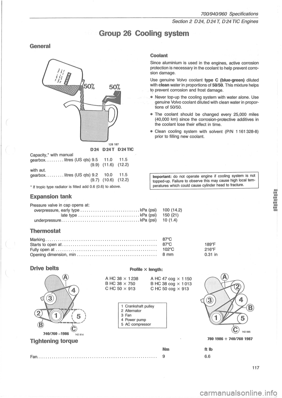
Drive belts Profile x length:
100 (14.2)
150 (21)
10(1.4)
87°C
87 °C
102°C
8 mm
A HC 38 x 1238
B HC 38 x 750
C HC
50 x 913
A HC 47 cog x 1 150
B HC 38 cog x 1 013
C
HC 50 cog x 913
--, / , I 5 I 1 I
--~_/
7401760 -1986 142814
Tightening torque
1 Crankshaft pulley 2 Alternator 3 Fan 4 Power pump
5 AC compressor
Nm
Fan.......................... ............................... 9
189°F
216 °F
0 .
31 in
780 1986 + 7401760 1987
ftlb
6.6
117
lit til' lit ,", ·111 11,1 ·111 1111 ,11'
--'